AN236282 Device Firmware Update (DFU) middleware (MW) for ModusToolbox
About this document
Scope and purpose
This document describes how to use the DFU MW to develop applications for Infineon's PSOC™ 4, PSOC™ 61, PSOC™ 62, PSOC™ 63,
PSOC™ Control
,
and XMC7000 MCU products. It includes a brief description of the
application programming interface (API)
,
build instructions
, and multiple high-level
use case descriptions
. The document also describes supported
File formats
and
Host command/response protocol
.
Intended audience
This document is intended for anyone who wants to use the DFU MW for PSOC™ 4, PSOC™ 6,
PSOC™ Control
,
and XMC7000 MCUs using ModusToolbox™.
Introduction
The Device Firmware Update (DFU) is a process to update the firmware in the device. The target device (e.g., MCU) and the host (for example, computer) establishes a connection to download the firmware. This connection can be either wired (UART, I2C, SPI, USB,
CAN FD,
etc.) or wireless (Wi-Fi, Bluetooth® Low Energy, etc.). Then, the target device receives the firmware from the host, validates, and executes it.
For PSOC™ and XMC7000 MCUs, Infineon offers DFU middleware (MW) which provides an over-the-wire update solution. If you are new to DFU, basic concepts and design principles are explained in following sections.
See the following resources for more information:
To learn about basic concepts and design principles, see What is DFU?
To learn about advanced concepts, if you are familiar with DFU concepts, see DFU middleware architecture
To learn about usage of DFU MW in ModusToolbox™, see Using DFU middleware in ModusToolbox™
To get the list of code examples based on DFU MW, see Code examples
Getting started
This section describes the background for the basic firmware update, how to build a DFU-capable application, and how to perform DFU operations. It explains the basic feature set provided by the DFU MW with the architecture it supports and the high-level sample use cases.
What is DFU?
DFU is a common part of MCU system design. Infineon’s DFU MW makes updating a product’s firmware in the field and factory possible over a serial interface. In a typical product, firmware is stored in an MCU’s memory. The MCU is mounted on a printed circuit board (PCB) and embedded in a product.
Figure 1
shows the data flow to the memory through the peripherals and ports of the end device.
Figure 1.
DFU data flow block diagram
Initial firmware programming into a product is typically done in the factory during PCB assembly, using the MCU’s JTAG or SWD interface. These interfaces may not be available or accessible on the field. A better way to update the firmware in the field is to use an existing connection between the product and the outside world. The connection may be a standard communication port such as I2C, USB, or UART. The DFU MW aids in the development of the firmware update solution over-the-wire (OTW). After installing the DFU-capable firmware on the device, it installs the subsequent applications.
Using DFU middleware in ModusToolbox
This section describes the process to create an application from scratch (an empty application), adding DFU MW to it, and using the DFU MW from top-level application files.
Note: This section contains only DFU MW-specific instructions. For detailed step-by-step instructions for using a ModusToolbox™ middleware, see ModusToolbox™ Help in ModusToolbox™ tools package user guide.
Ensure that the development environment has all the software set-up required for the application to build. For using DFU MW with the application in ModusToolbox™ follow these steps.
Note: Instructions mentioned are to include DFU MW in an empty application. However, the DFU MW can be added to an existing ModusToolbox™ project using similar steps (Steps 6 and 7). Alternatively, use the CE232504 - PSOC™ 6 MCU: Basic Device Firmware Upgrade (DFU) code example to get started.
Open Eclipse IDE for ModusToolbox™.
To add DFU MW to an application, create an empty application.
Click .
Select the respective target, and then click Next.
Under Getting Started, select Empty Application, and then click Create.
From the Quick Panel, open Library Manager.
Switch to the Add Library tab. In the middleware section, check the checkbox in front of the DFU library.
Click Update in the Library Manager dialog box.
Include cy_dfu.h in the main.c file of the application project.
Note: While selecting the middleware, ensure that you are using the desired version. If you want to use the same middleware in multiple projects, in the workspace ensure that the MW source is fetched to the mtb_shared directory.
After following these steps, the application makes use of the capabilities of DFU MW for the firmware update solution.
DFU middleware based solution types
DFU MW can be used to build two broad categories of firmware update solutions by developing either
DFU middleware for the bootloader
or
DFU middleware for user application
. The
following table summarizes the DFU MW support category respect to MCU and
following section discusses both approaches in detail.
Solutions | Device support | |||
|---|---|---|---|---|
PSOC™ 4 | PSOC™ 61, 62, 63 | XMC7000 | PSOC™ Control C3 | |
Bootloader using DFU MW | Yes | Yes | No 1 | No 1 |
User application using DFU MW | No 1 | Yes | Yes | Yes |
Bootloader using DFU middleware
DFU MW can be used to build a small footprint bootloader for Infineon MCUs. It is ideal when the selected MCU cannot support a large footprint bootloader such as MCUboot or may have any other use case-specific constraints.
Figure 2.
DFU MW application design
shows a typical DFU MW-based bootloader with transport capability which can download the firmware to the memory, validate it, and start the execution. For more details, see
DFU middleware for the bootloader
.
The DFU MW supports developing bootloaders both with and without transport. For example, you can build a DFU-based bootloader with transport capabilities such as UART, USB, etc. Whereas another use case may build the DFU-based bootloader without any transport.
Selection of DFU MW-based solution
section describes how to decide and when to use transport in the bootloader and application.
Irrespective of the transport configuration selected, the bootloader can perform the validation and installation of the application image to the boot regions as required.
User application using DFU MW
DFU middleware can be used to design a full-fledged application project with transport capabilities to communicate with the host device.
Note: PSOC™ 4 does not support bootloaders design the one described in this section because of the limited amount of memory to have an application staging area. Therefore, skip this section for PSOC™ 4 implementations.
Figure 3.
DFU MW application design
shows the high-level block diagram for the use case of DFU MW in the user application, which downloads the new firmware image from the host machine to the staging region. Bootloader validates the image, installs it, and transfers the control to the newly installed image. In this case, you can have the bootloader based on DFU MW or select any other bootloader solutions (such as MCUboot based) as the use case demands. For more details, see
DFU middleware for user application
.
Selection of DFU MW-based solution
As described in the earlier sections, DFU MW is used to design a bootloader or an application with transport as the update solution for the end device. This section discusses when you use the DFU MW to develop an end application with transport or a bootloader.
The following matrix helps in deciding the DFU solution to opt for; either the bootloader using the DFU MW for transport and bootloading operations or the user application using the DFU MW for transport.
Bootloader using DFU MW | User application using DFU MW | |
|---|---|---|
Application downtime | HIGH | LOW |
Memory requirement | LOW | HIGH (staging) |
Power fail safe | No (only recovery on failure) | Yes |
provides the comparison for the following factors which helps to select the update solution according to the use case requirement:
Application downtime: While using bootloader flows, device execution remains in the bootloader while waiting for an update, during the whole-time the end application cannot be executed. Whereas, in the application flow, the end application can execute while the device gets the update, therefore, which reduces the downtime.
Memory requirement: The application flow requires more memory to store the application in the staging area while downloading, but it ensures application recovery on update failure.
Power fail safe: As the update is stored in a secondary region in the application flow, during the update, there is always a valid image in the application boot region to execute even in the event of power failure during the update process.
According to the use case, based on the above factors, you can select the application flow or bootloader flow for the update solution.
DFU middleware features
This section describes the basic features offered by the DFU middleware.
Transport for communication
DFU MW acts as a wrapper for the transport between the target and the host. It also provides the options to select the transports, configure them, and use them in the end applications. I2C, SPI, UART,
CAN FD,
and USB-CDC are supported out-of-the-box (OOB). See
CE232504 - PSOC™ 6 MCU: Basic Device Firmware Upgrade (DFU)
,
CE236395 - PSOC™ 4: Basic Device Firmware Upgrade (DFU)
, and
CE237943 - XMC7000 : OTW firmware upgrade
code examples.
Note: PSOC™ 4: Basic Device Firmware Upgrade (DFU) code example supports only I2C and UART as transport layers.
Figure 4.
Generic DFU system
The transport layer of the MW configures the Hardware Abstraction Layer (HAL)/Peripheral Driver Library (PDL) drivers to set up the target for communication with the host. It uses the simple
Host command/response protocol
for communication regardless of the channel used for communication. The DFU MW provides a medium to receive the commands from the communication channel and responds to each command by sending one or more bytes to the communication channel. See
Figure 4
.
The commands and responses are in the form of a byte stream, packetized in a manner that ensures the integrity of the data being transmitted. A packet validity check method is included and consists of a 2's complement 16-bit checksum or CRC-16CCITT. See
Host command/response protocol
for details.
Dynamic selection of interface
DFU MW supports multiple serial interfaces to communicate with the host to receive and send data or firmware images for the device.
Table 3
shows the typical communication interface supported across the given device family.
Driver(s)/middleware(s) | Device support | |||
|---|---|---|---|---|
PSOC™ 4 | PSOC™ 61, 62, 63 | XMC7000 | PSOC™ Control C3 | |
UART, I2C, SPI | Yes | Yes | Yes | Yes |
EMUSB_HID | No | No | No | No |
EMUSB_CDC | No | Yes | No | No |
CAN FD | No | No | Yes | Yes |
DFU MW supports the runtime selection of the serial communication interface between the host and target. The firmware is built with either one or more interfaces or deployed onto the target. If the firmware is built with multiple interfaces, the application dynamically decides to select any of the pre-built interfaces based on use case logic. For example, a DFU application built with I2C and UART interfaces can select either I2C or UART to communicate with the host without rebuilding the application. During runtime, the application can select one of the enabled transports to start as shown in
Figure 5
.
Note: The dynamic selection feature requires the application to select a DFU interface before starting the DFU session. If a change of interface is required, the application must stop the ongoing DFU session and start a new DFU session with the newly selected interface.
Figure 5.
Dynamic switching of transport
Follow these steps to enable the switching of interface:
To enable the transport in the DFU application, add the required transport in the components to enable the specific transport needs through the Makefile. Include the required transport source transport_interface.c files in the Makefile.
COMPONENTS = DFU_I2C DFU_UART DFU_USB_CDC DFU_SPI
During runtime, use a global variable to select/define a transport interface.
cy_en_dfu_transport_t transport_interface = CY_DFU_Transport CY_DFU_I2C
Pass the global variable to select needs while starting the DFU communication using transport start.
Cy_DFU_TransportStart(transport_interface);For switching the transport dynamically during runtime, calling the transport stop needs to de-initialize the existing transport and pass the new transport to be used as a parameter to transport start.
Cy_DFU_TransportStop ();
transport_interface = CY_DFU_UART;
Cy_DFU_TransportStart(transport_interface);
The transport start API internally checks for the passed interface to be selected and included while building and initializing the selected interface communication channel.
Error detection
The DFU MW enables two levels of error detection; packet level and whole image level.
Packet level checksum
The DFU MW provides two checksums for enabling the secure transmission of a packet which include the basic summation and CRC-16CCITT.
The basic summation checksum is computed by adding all the bytes (excluding the checksum) and then taking the 2's complement.
CRC-16CCITT - The 16-bit CRC using the CCITT algorithm. Select the packet checksum type with the CY_DFU_OPT_PACKET_CRC macro in the dfu_user.h file
CY_DFU_OPT_PACKET_CRC --> 0 - basic summation (default).
CY_DFU_OPT_PACKET_CRC --> 1 - for CRC-16.
Image level checksum/HASH
The DFU MW supports a checksum (CRC-32) or HASH (SHA1) within the application firmware image to validate the image downloaded to the target. DFU MW uses CRC-32 as the default checksum for application images.
However, according to the availability of hardware cryptographic block SHA1 can be used for checksum validation during build time configurations. Advanced hashing and signature solutions can be developed and must be taken care of within the application scope. The above checksum is required only when DFU MW is used for bootloading operations. In case, DFU MW is not used for the bootloader, a specific bootloader solution must take care of the application integrity validation.
Infineon recommends using an MCUboot-based bootloader solution for secured boot and secure firmware upgrades.
Note: PSOC™ Control does not support image-level checksum/HASH feature from DFU MW.
DFU MW ecosystem
To develop a DFU application and perform DFU on the Infineon PSOC™ and XMC7000 MCU family, a few tools are required as follows:
ModusToolbox™ software: A modern extensible development environment for Infineon microcontroller devices, including PSOC™ Arm® Cortex® microcontrollers, XMC™ industrial microcontrollers, AIROC™ Wi-Fi devices, AIROC™ Bluetooth® devices, and USB-C High Voltage microcontrollers. Infineon provides ModusToolbox™ GUI and command line options for Windows, macOS, and Linux to provide a single, coherent, and familiar design experience.
Note: This document contains details related to the DFU middleware usage in ModusToolbox™ only. For details on how to use DFU middleware in legacy PSOC™ Creator see AN213924 - PSOC™ MCU Device Firmware Update (DFU) software development kit guide.
DFU Host Tool (DHT): A stand-alone program provided with the ModusToolbox™ software. It communicates with Infineon MCUs, which are programmed with a DFU over serial-capable firmware.
The tool is available under the ModusToolbox™ installation path of </ModusToolbox/tools_<version>/dfuh‑tool/>. This is an example of the “host” shown in Figure 4. For more information, see DFU Host Tool. Host tool is also released in source and available at the ModusToolbox™ installation path.
CyMCUElfTool: A command line utility used in the build process of MCUs that provides facilities for signing important data structures, including generating digital signatures, merging ELF files, and generating bootloadable data for use with the MCU for DFU middleware library. Use this utility only when the .cyacd2 file format is used. The tool is only used for firmware updates using DFU MW-based bootloader.
CyMCUElfTool is released as an executable under ModusToolbox™ installation path </ModusToolbox/tools_<version>/cymcuelftool/>. This program is used in building the application, as shown in Figure 13.
A user guide is available under ModusToolbox™ installation path <~\CyMCUElfTool 1.0\doc>.
File format and MCU support
Edgeprotecttools: Edgeprotecttools is a python-based security package that provides a command-line interface to interact with the MCU for various purposes, including provisioning, device integrity checks, RMA transition, factory reset, and more. It is used for attaching image header, sign images, and generate update images for MCUboot-based bootloader for PSOC™ Control.
The tool is available with ModusToolbox™ Edge Protect Security Suite. Install the suite using
Infineon Developer Center Launcher
.
Infineon Programmer (optional): A flexible, cross-platform application for programming various MCU and connectivity devices. It can program, erase, verify, and read the flash of the target device.
There are a few other elements listed below, which DFU MW requires, but are not provided under DFU MW release. They are part of the ModusToolbox™ release or respective open-source library releases.
JSON Parser: This utility is embedded in the Host Tool to parse the JSON file to extract the necessary data before sending the actual data. The parser extracts the necessary metadata, such as device ID, die ID, and version number.
Device drivers: For communication, flash, etc.,are in the folder ... /ModusToolbox/libraries/device/components/PDL/HAL drivers. They are called as needed by the DFU API functions.
Imgtool: The Python program
scripts/imgtool.py(part of EdgeProtectTools package) is used to perform the operations that are necessary to manage keys and sign images when using MCUboot as a bootloader. This tool currently supports RSA-2048, RSA-3072, ECDSA-p256, and ed25519 keys. For details, seeMCUboot
. The tool is used for firmware updates using an MCUboot-based bootloader.
You can generate a keypair for one of these types using the ‘keygen’ command
"./scripts/imgtool.py keygen -k filename.pem -t rsa-2048"
or use rsa-3072, ecdsa-p256, or ed25519 for the type. The key type used must match what MCUboot is configured to verify. For more details on key generation, see MCUboot code example
CE230650 - PSOC™ MCU: MCUboot-based basic bootloader
.
DFU middleware resources
The section details the resources and assets which are provided by the DFU MW. It discusses the files provided by the MW for the configuration and references to the APIs which can be used while building a DFU MW-based solution. For more details regarding the assets from the DFU MW, see the
API reference documentation
. The DFU MW provides multiple sets of files to help configure the device for update solutions such as
linker
files,
Makefile
, and source code.
Table 4
lists the files required for building an application using the DFU MW.
File | Description | |
|---|---|---|
cy_dfu.h, .c | DFU MW files | |
cy_dfu_bwc_macro.h | Enables backward compatibility with the legacy bootloader SDK | |
dfu_user.h | Contains user-editable statements that control the operation and the enabled features in the MW | |
dfu_user.c | Contains user functions required by the MW core:
| |
transport_uart.h, .c transport_... .h, .c | Contains the DFU transport functions for the host communication channel being used. These functions are typically called by the transport functions in . | |
dfu_cm4.ld, dfu_cm0p.ld | Custom GNU Compiler Collection (GCC) linker scripts | In each application, these linker script files replace the default linker script files provided by the board support package (BSP). These files locate the code and data sections for each of the CPUs as well as the DFU module and other regions. These files exist only as a reference and can be modified as required for the end application. Note: Template linker scripts are only available for PSOC™ 4 and PSOC™ 6 devices. |
dfu_cm4.scat, dfu_cm0p.scat, dfu_mdk_common.h, dfu_mdk_symbols.c | Custom Arm® MDK linker scripts; the common files exist to create necessary symbol definitions. | |
dfu_cm4.icf, dfu_cm0p.icf | Custom IAR compiler linker scripts | |
The DFU MW provides a set of interface functions for developing the DFU MW-based firmware update solution. For details of the APIs and related identifiers provided by the MW, see the
API reference.
The core of DFU MW is implemented in
cy_dfu.c
. It utilizes a few user-defined functions (defined in
dfu_user.c
), therefore, allowing the customization of the DFU flow without altering the core of the DFU protocol.
Following DFU operations are customizable through user-defined functions:
Host communication, also called transport functions or communication interface APIs
Reading and writing the device’s memory and other nonvolatile memory (NVM), for example, external flash
shows the list of functions provided by the DFU MW library.
Function | Description |
|---|---|
For host communication. Examples are in
dfu_user.c and transport_xxx.h and .c files | |
Cy_DFU_TransportStart() | Opens and initializes the communication channel |
Cy_DFU_TransportStop() | Closes the communication channel |
Cy_DFU_TransportReset() | Re-initializes the channel, typically to bring it back to a known state |
Cy_DFU_TransportRead() | Receives a packet from the host; see Command/response packet structure |
Cy_DFU_TransportWrite() | Sends a packet to the host; see Command/response packet structure |
For NVM access. Examples are in dfu_user.c | |
Cy_DFU_ReadData() | Reads data from the device flash or other NVM |
Cy_DFU_WriteData() | Writes data to the device flash or other NVM |
DFU middleware architecture
This section details the architecture of the DFU MW library and describes how it helps to develop a firmware update solution. It describes the working of the middleware on high-level use cases and its functioning at low-level.
Figure 7.
DFU MW layered architecture
shows the architecture of the DFU MW. It shows a generic flow of the DFU MW-based application and explains the execution flow divided into four layers.
Application:
The application uses various DFU APIs, resources, and features provided by the DFU MW. The application layer consists of the application code, user files such as linker scripts,
dfu_user
files transport, and
Makefile
. It is built on top of the device-specific BSP and drivers.
Middleware:
Middleware consists of the core implementation of DFU protocol shown as the
DFU-Core
component in
Figure 7
. It also provides configurable parameters, commands, access to low-level communication drivers, memory operations, and interface functions shown as the
DFU-User
. You can modify keeping the core protocol unchanged.
Middleware layer provides an API handler and various identifiers for the DFU commands. It can optionally validate the applications. This layer can be used as-is by the end application.
Driver:
It provides all the driver’s support to the application and DFU MW to interact with the hardware. To simplify the application software development, MW abstracts the drivers (PDL/HAL).
Hardware:
This is the actual hardware IP responsible for physical action requested by the application.
DFU workflow
The DFU process takes place through a series of command-response pairs provided by the DFU MW.
Figure 8
shows a typical flow of command and response between the host and the target device in a DFU session.
Figure 8.
Typical DFU session
A DFU session always starts with an
Enter DFU
command from the host to the target. After the target acknowledges the command from the host, the DFU session will be established. Commands and responses are exchanged between the host and the target to perform a specified job, such as data transfer. A session can be terminated with an
Exit DFU
command to the device from the host or by a pre-defined timeout of an inactive window.
As shown in
Figure 8
, the host sends the firmware/data to the target by using a series of
send data
commands with data for a single row followed by a
program data
command for each row to instruct the device to write particular row data into device memory. Similarly, the host can verify and erase the image by sending appropriate commands. For more details, see the
Host command/response protocol
.
Using the DFU middleware
DFU MW can be used to develop high-level use cases identified in the
DFU middleware based solution types
in various ways to realize an end-use case. This section details a few of those options that are typically used and demonstrated by Infineon OOB. To get started, see
Using DFU middleware in ModusToolbox™
.
In the following sections, the bootloader is represented as "Application #0" in all use cases, whereas "Application #1- - - - Application #N" is the user application.
DFU middleware for the bootloader
Note:
This section is not applicable for
PSOC™ Edge
and
PSOC™ Control
devices.
The DFU MW can be used to design various applications according to the requirement.
Using DFU middleware in ModusToolbox™
shows the typical usage of the DFU MW in application development.
Bootloader using DFU middleware
provides an overview of the usage of the DFU MW to design the bootloader. The bootloader using the DFU MW can be designed with or without transport.
shows the typical flash map for the specific use case of designing an update solution having a bootloader using the DFU MW. In the given use case, the application can also be a part of the external memory instead of the one shown in
Figure 9
.
Designing a bootloader using the DFU MW requires a special structure to store the information regarding the applications stored in the device. The structure is known as "Application metadata", which contains the address and size information of all the applications stored in the device. This structure is stored at the end of the nonvolatile memory.
Application metadata uses to extract the size and start address information for the application at runtime. The bootloader uses this information to validate the application firmware and transfer control to the particular application during runtime. For more details, see
Appendix A: Application metadata
.
Figure 9.
DFU MW bootloader use case
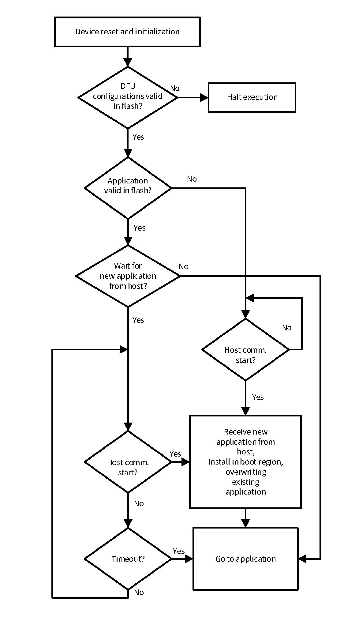
Bootloader operations
The bootloader is a crucial component of the firmware update solution. Typically, the bootloader validates the next stage application and passes the execution control to the same. Additionally, the bootloader communicates with the host to download a new firmware image if a transport interface is available.
shows the operation of the DFU MW bootloader with a transport interface, which will directly download and install the new application image on the primary boot slot directly after validating the same if required, as shown in
Figure 10
.
This use case demonstrates the update solution where a bootloader itself is responsible for connecting with a host, downloading the application, validating it, and transferring control to it as shown in
Figure 10
.
The solution may optionally require the application image to be signed with a signature during build time. To include the download feature to the bootloader, the
dfu_user.c
file must have the definition of read, write API (
Cy_DFU_ReadData(), Cy_DFU_WriteData()
) pointing to the address of the application boot region. After the download of the image, before execution, the image can be validated by the bootloader. If valid, the bootloader transfers control to the downloaded application. The DFU MW provides a reference implementation of the API for validation of the firmware image and boot to the same. The basic flow of creating a DFU MW-based application is the same as provided in
Using DFU middleware in ModusToolbox™
.
Figure 10.
DFU MW in bootloader flow
DFU middleware for user application
The DFU MW can be used with the end user application to enable a transport interface for communication with the host. The usage of the middleware with the end application reduces the downtime of the system during the update process as described in
User application using DFU MW
.
An application with the DFU MW communicates with the host machine via a serial interface to download the firmware/receive commands from the host. Such an application downloads the new application firmware for update and park it to the staging region as shown in
Figure 11
and passes the execution control to the bootloader. The bootloader validates the firmware, installs it, and boots to the new application.
Figure 11.
DFU MW application use case
In this case, the application must include the DFU middleware to communicate with the host. The
dfu_user.c
file must have the implementation to download, read and write the new application firmware from/to the staging region.
While the application downloads the image, the bootloader installs the images after successful validation. The developer can decide to have the bootloader of its own choice. For example, use DFU, MCUboot, or any other bootloaders of your choice.
Note:
Figure 11
shows CM0p as an illustration considering PSOC™ 6 as reference, it can be any CPU core as supported by device.
MCUboot-based bootloader
This section demonstrates the scenario where the DFU MW is a part of the end application, whereas the bootloader uses the open-source MCUboot for updates. The application uses the DFU MW as the transport protocol to use the serial interface to communicate with the host and download the MCUboot-compatible hex for the next application image.
The user application downloads the new image to the secondary slot and transfers the control to the bootloader. The bootloader based on MCUboot performs the next level validation check and depending on the configuration, it swaps or overwrites the image of the secondary slot to the primary boot slot if the secondary slot is valid. After the transfer to the primary slot, MCUboot verifies the primary image and boots to the same if verified.
As shown in
Figure 11
, this use case requires the MCUboot library to develop the bootloader and the applications having DFU MW to download the update of the user application, which will be MCUboot-compatible. The user application with the DFU MW uses the secondary slot for the MCUboot image as a staging area to store the new image of the application according to the MCUboot image format.
Figure 12.
MCUboot-compatible image generation
shows the typical process to generate the MCUboot-compatible firmware image and feed it to the Host Tool. Provide the hex data of the application image to the MCUboot image tool, which generates the digitally signed hex; this image can be optionally used to generate a DFU MW-compatible. cyacd2 image file format using the ‘CyMCUElfTool’ for PSOC™ device families and .mtbdfu file format for
PSOC™ Control
and
XMC7000 device family.
Note:
DFU MW does not provide a custom script to convert hex to a .cyacd2 file. You can generate your script for the same. Moreover, this script requires additional parameters to generate a .cyacd2 file from a given hex file. See
.cyacd2 file format
for details.
As the MCUboot-based bootloader has a larger footprint compared to the DFU MW, Infineon recommends utilizing this use case on devices that are not memory constrained.
MCUboot is an open-source infrastructure for the bootloader solution for microcontroller systems; see the
MCUboot guide
.
The MCUboot compatibility feature refers to downloading the firmware image, which is acceptable by the bootloader based on the MCUboot. For more information on the MCUboot image format, see the “Image” section of the
MCUboot guide
. Firmware downloaded must get validated and authenticated by the MCUboot bootloader before execution. Enabling this feature in the application provides an extra level of security to the update solution and helps to develop a secured firmware update solution for the device.
Note:
Enable the feature by selecting the DFU flow as MCUboot flow using the macro defined in the application
Makefile
. To enable this feature in the DFU MW, add the
CY_DFU_FLOW=CY_DFU_MCUBOOT_FLOW
define in the application
Makefile
. This define enables the DFU MW to download the firmware available in the MCUboot format from the host and stage it to the secondary slot for the bootloader. The feature enables you to sign your image with proven signing algorithms including RSA-2048, RSA-3072, ECSDA-P256, and ED25519.
Note:
PSOC™ Control
device only support
CY_DFU_MCUBOOT_FLOW
, as a default flow.
DFU middleware-based bootloader
The DFU MW is used with the bootloader and application, where you can divide the task required for the update solution between the two projects. This use case demonstrates the scenario where the application and bootloader use the DFU MW and have respective tasks in the update process.
As shown in
Figure 11
, this use case requires the DFU middleware library to develop the bootloader and the user application to download the next version of the user application, which will be in the DFU MW standard format. The user application with the DFU MW uses the staging area to store the new image of the application according to the requirement of the bootloader. After the download, the application switches the control to the bootloader.
A bootloader designed for the use case has a small footprint based on the DFU MW. The bootloader does not have support for a transport interface but will have the capability to validate the application from the secondary slot and copy the same to the primary boot region if valid. The application handles the initializing of the DFU transport and communicates with the host machine to download the new application to the secondary slot. After a successful download, it transfers the control to the bootloader for verification and booting.
The application download will remain similar to the above use case. This firmware image in the DFU MW standard format will be generated by the ‘CyMCUElfTool’ provided with the ModusToolbox™. The MCUboot-compatible image will not be supported in this use case.
For the specific use case, the bootloader must verify the user application from the secondary slot if valid using the
Cy_DFU_ValidateApp()
API and copy the image to the boot section. After successful copying of the image, the bootloader must pass the execution to the boot region to execute the newly downloaded firmware.
Selecting the bootloader
The bootloader flow solution uses the bootloader designed using DFU MW, whereas the application flow solution targets use the application with DFU MW. The application flow solution requires selecting the bootloader for the solution; it can either use MCUboot or DFU MW for designing the same.
Selection of DFU MW-based solution
section describes how to select DFU MW for app vs DFU MW for the bootloader above.
The following matrix simplifies the selection of the bootloader solution either using the open-source MCUboot approach or using DFU MW while using DFU MW for application.
MCUboot approach | DFU MW approach | |
|---|---|---|
Complexity | High | Low |
Features | High | Limited |
Security | Advanced | Minimal |
FW image format | MCUboot defined | DFU MW defined |
helps to select the bootloader for the update solution on the following factors:
Complexity:
DFU MW uses a basic checksum and launching process for bootloading, while MCUboot uses a complex algorithm for verification of next-level image and launching process of next-level application including aligning, clean allocation, and de-allocation of RAM/stack memory.
Features:
DFU MW provides basic features for a small footprint bootloader, whereas MCUboot provides multiple features such as measured boot, Fault-Injection-Hardening (FIH), and encryption, which results in a bulky bootloader.
Security:
DFU MW provides only bare minimal integrity checks for images by CRC or HASH whereas, MCUboot uses strong and complex hashing and signing methods to maintain the authenticity and integrity of the image. Therefore, can be used for a secured boot for secured upgrades.
FW image format:
DFU MW only expects the hash or CRC checksum with the image, whereas MCUboot mandates the image format which contains the header and footer defined by the MCUboot.
Based on the use case, you can select the bootloader based on MCUboot or DFU MW according to the above factors wherever applicable.
Developing DFU applications in ModusToolbox
This section provides instructions for using the DFU MW to build applications. It contains the details to modify the DFU MW-configurable files to use the middleware for specific use cases.
Note:
This section contains only DFU-specific instructions. For detailed step-by-step instructions for creating a ModusToolbox™ application, see the ModusToolbox™ Help,
Eclipse IDE for ModusToolbox™ user guide
, or
Code examples
section in this document.
DFU applications are not necessarily to be user applications. The DFU-based bootloader is also considered a DFU application. So, the following section is applicable in all cases where DFU MW is used.
The next step is to design the applications using the DFU MW feature. Each application is a single ModusToolbox™ application independent from any other application. With ModusToolbox™, you can have all the applications in one workspace or in separate workspaces, as well as in separate locations on your computer. Before getting started with the MCU application, developing a plan for workspaces and applications for your overall system development needs is recommended.
DFU MW application process flow
Application development includes the design and builds flows. This section explains the flow of the application design and development of the DFU MW-based application using an IDE with the configurator tools. It discusses the design, build, and required post-build actions to be taken for the application based on DFU MW to download the firmware.
Figure 13
provides the application build process:
Creation of the DFU MW-based application project in ModusToolbox™ or any other supported IDE, see
Using DFU middleware in ModusToolbox™
.
Modification of the source file such as
linker script
,
Makefile
, and
design.modus
for DFU compatibility.
Modifying the customizable files (
dfu_user
) according to the requirement of the application, see
DFU workflow
for more information.
Figure 13.
ModusToolbox™ application build and DFU process diagram
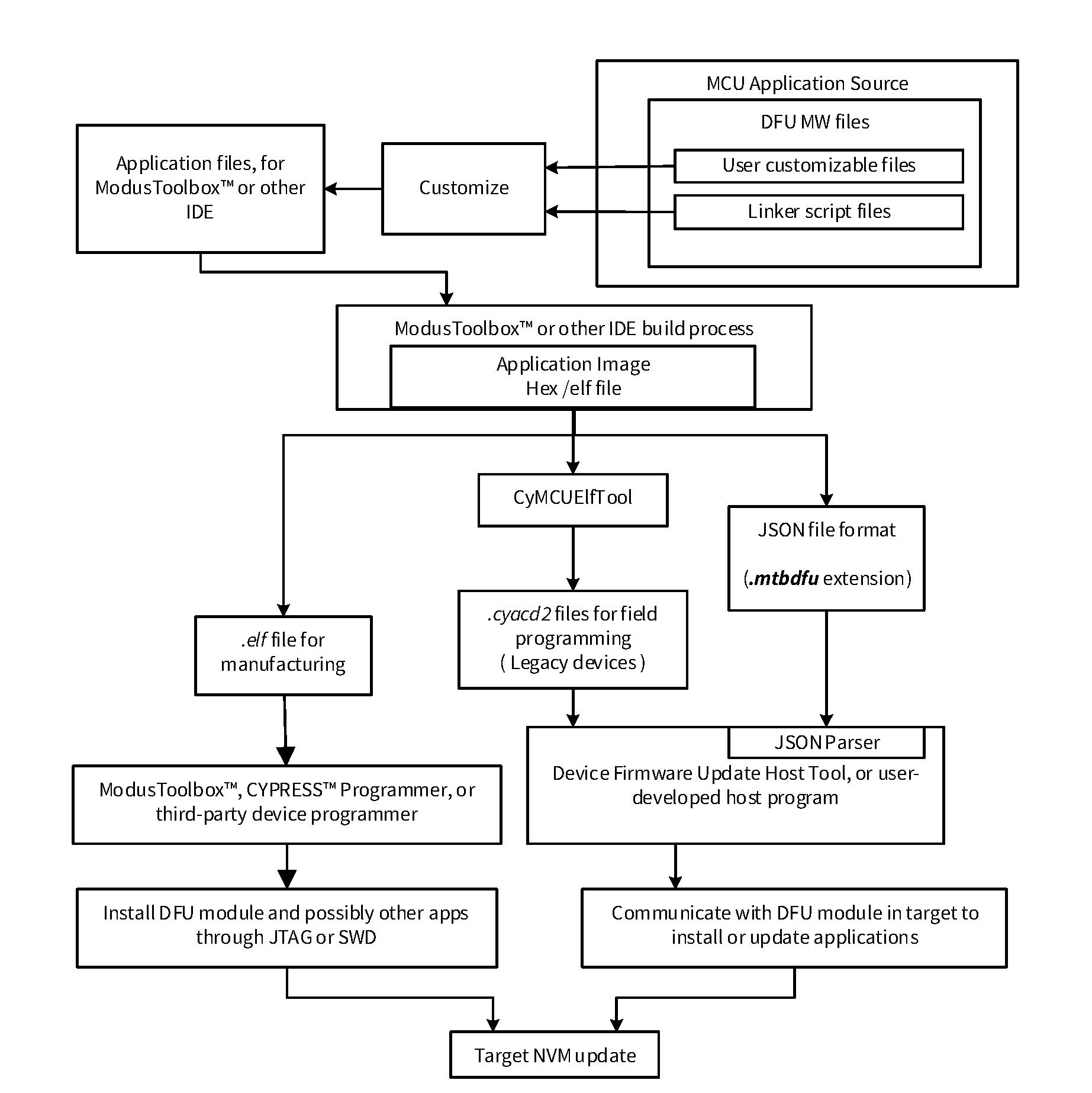
Build the application project using the Eclipse IDE for ModusToolbox™ or any compiler and generate the binary (ELF) file.
Sign the binary image and convert it to hex format using the IMGTool; optionally, the elf/hex file can be converted to a
.cyacd2
file using the ‘CyMCUElfTool’ or python scripts.
For a manufacturing use case, use the ELF file with the programmer and debugger tools to download the firmware.
For an on-field use case, select the
.cyacd2
file or generate the JSON file with the required information as the input for the host tool. See
File formats
for details on input files.
Use the host tool to download the firmware to the device using a serial interface and to send the
miscellaneous
commands to the target for sending the data, file, or provision of the device, etc. via a serial interface using the JSON file with the appropriate information and configuration. See the
ModusToolbox™ DFU Host tool user guide
for more details.
Do the following for each existing ModusToolbox™ application that is to use DFU operations and/or be installable:
Note:
While creating a new application based on DFU MW, see
Using DFU middleware in ModusToolbox™
and skip Step
4
.
- If the application requires to use transport for DFU, enable the communication peripherals (such as UART, I2C, etc.,) in the design.modus file in the bsp directory. Those peripherals implement the communication channel to the DFU host.
The DFU MW includes support for communication channel types, including UART, SPI, I2C,
CAN FD,
and USB. See
Code examples
and
References
.
You can also create a custom communication channel. The driver must implement the transport functions described in
Communication interface APIs
.
Incorporate the DFU MW into the project, as shown in
Figure 14
. Right-click the project in the
Project Explorer
window and click
.
Figure 14.
Incorporate DFU MW into a ModusToolbox™ project
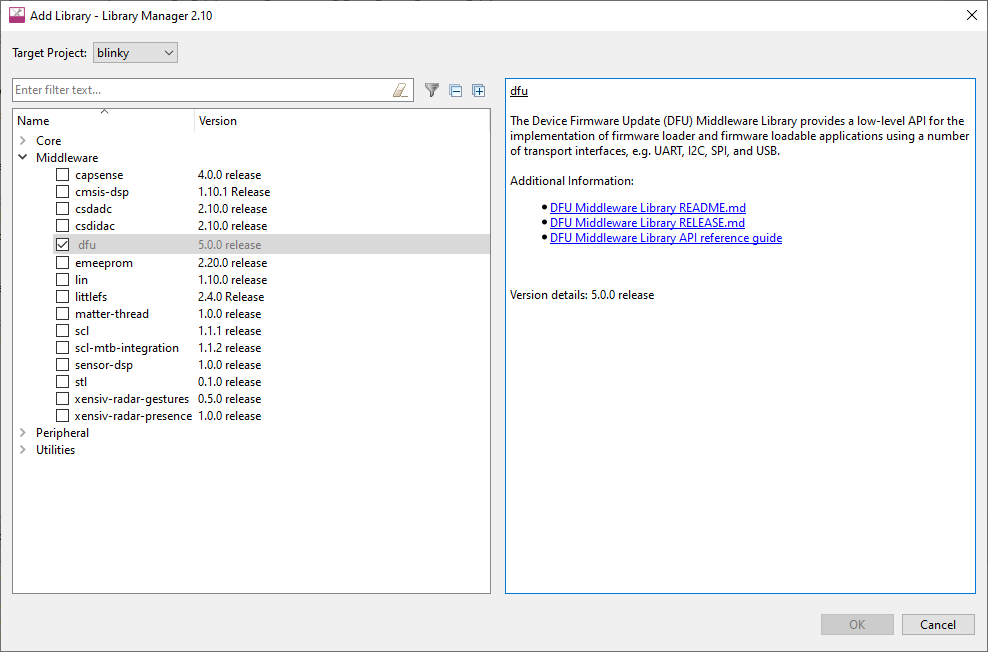
If the application is required to perform DFU operations, select
dfu
from the middleware section. Click
Update
when done.
- Include the path to the DFU MW library in the Makefile. Required source .c, .h, and linker script (e.g., .lD) files will be automatically included in the project during build time.
- Installed linker script files are by default set up for Application #0 (App0). For otherapplications, edit the files by changing the application number. The following example shows the edits for the downloadable application, for the GCC linker.
- Change the project Makefile to use the DFU linker script files instead of the default linker script files. Provide the relative path to the file to the LINKER_SCRIPT macro in the application Makefile to use the custom linker script.
For downloadable application projects, add a post-build command to sign the image and convert the binary to HEX or .cyacd2 using the open-source imgtool or CyMCUElfTool.exe/custom scripts according to the use case.
/* Post-build commands in Makefile for generating .hex file, when Using MCUboot
for bootloader */
cp -f $(BINARY_OUT_PATH).hex $(BINARY_OUT_PATH)_raw.hex;\
rm -f $(BINARY_OUT_PATH).hex;\ /* Copy hex to raw.hex file */
$(CY_ELF_TO_HEX_TOOL)--change-addresses=$(HEADER_OFFSET)
$(CY_ELF_TO_HEX_OPTIONS)$(BINARY_OUT_PATH).elf $(BINARY_OUT_PATH)_unsigned.hex;\
/* address translation */
$(PYTHON_PATH)$(IMGTOOL_PATH)$(SIGN_ARGS)$(BINARY_OUT_PATH)_unsigned.hex
$(BINARY_OUT_PATH).hex; /* Signing */Note: See CE230650 - PSOC™ 6 MCU : MCUboot-based basic bootloader post builds for details.
/* Post-builds commands in Makefile for generating .cyacd2 file, when DFU MW flow
for bootloader */
$(CY_MCUELFTOOL) --sign $(CY_CONFIG_DIR)/$(APPNAME).elf CRC --output
$(CY_CONFIG_DIR)/$(APPNAME)_crc.elf && \ /* Signing of image */
$(CY_MCUELFTOOL) -P $(CY_CONFIG_DIR)/$(APPNAME)_crc.elf --output
$(CY_CONFIG_DIR)/$(APPNAME)_crc.cyacd2 \ /* .cyacd2 generation */Note: See CE232504 - PSOC™ 6 MCU : Basic Device Firmware Upgrade (DFU) post builds for details.
Add code as needed to
main.c
and other source files. Specific requirements are:
Add a
#include
"
cy_dfu.h
" statement to all source files as needed to access the DFU MW API.
For downloadable applications, in
main.c
in the application project, add the following global statement. Adjust the array size for the selected signature type. This step is required only for firmware updates using DFU MW-based bootloader
/* This section holds signature data for application verification.
When DFU MW flow for bootloader
*/
CY_SECTION(".cy_app_signature") __USED static const uint32_t
cy_dfu_appSignature;Note:
This is not applicable for
PSOC™ Control
device.
For downloading applications, in
dfu_user.c
in the application project, modify the following callback functions to download the application at the required locations.
Specify the DFU callback function(s) to call:
Cy_DFU_WriteData()
: Modify the address sanity check and add the offset of primary to the staging region to download the image to the secondary region; for image download only.
Cy_DFU_ReadData()
: Modify the address for sanity checks and add the offset of primary to the staging region while verifying the image.
In your overall code in both main files, consider the following:
Specify the DFU function(s) to call:
Cy_DFU_Complete()
: Blocks while doing the entire DFU operation. Call this function if there is no other task to do during DFU.
Cy_DFU_Init()
followed by a series of calls to
Cy_DFU_Continue()
:
Cy_DFU_Continue()
blocks while receiving, processing, and responding to one command packet from the host. Call these functions if other tasks must be done during DFU.
Specify whether each application will pass control to the other application. Add calls to the DFU MW API functions
Cy_DFU_ValidateApp()
and
Cy_DFU_ExecuteApp()
as required.
For more information, see the DFU MW documentation.
- Application must include a switching mechanism, which will be responsible for switching the application to the bootloader or another application (if applicable) using the DFU MW API Cy_DFU_ExecuteApp(). For example, in a system with a bootloader and a single application, where the __cy_app_id is 0 for the bootloader and 1 for the application, calling the DFU MW API Cy_DFU_ExecuteApp(0) transfers the control from the application to the bootloader. Note: This is not applicable for PSOC™ Control device.
/* DFU MW specific: aliases regions, so the rest of the code does not use
application-specific memory region names */
/* Create flash and ram sections for User Application in blinky_cm4 linker files */
REGION_ALIAS("flash",       flash_app1);
REGION_ALIAS("ram",           ram_app1);
/* DFU MW specific: sets an app Id */
__cy_app_id = 1;
DFU middleware application with an RTOS
DFU MW-based applications can be developed for both bare metal as well as Real-Time Operating System (RTOS) environments. Basically, the use of an RTOS environment brings in the advantage of threading and adds real-time behavior to the application for time-critical use cases. The DFU MW architecture is RTOS-independent; RTOS-based applications using DFU MW can be used with various available RTOSes. For more details, see
RTOS abstraction
.
However, Infineon does not limit the RTOS-specific functionalities and APIs for custom configuration for DFU MW-based applications. Usage of an RTOS environment is a developer choice, which enables the developer to design time-critical and efficient solutions.
DFU in multi-core device
DFU MW support is core-agnostic; it enables support for applications independent of the execution core. DFU MW-based projects can be ported to any core with a few modifications required in the project source.
The PSOC™ 6 DFU basic focuses on the execution of the DFU project on two cores. The DFU MW supports the execution of applications on any core.
The available DFU ecosystem supports multiple scenarios for multiple core platforms, but the following scenarios are verified.
Note:
This section references for PSOC™ 6 and PSOC™ 4 MCUs for demonstration. The same applies to XMC7000 MCU.
Bootloader and application on separate cores
This scenario provides the use case where the bootloader executes from the CM0p core and the Blinky application executes from the CM4 core as shown in
Figure 15
. This use case is demonstrated in
CE232504 - PSOC™ 6 MCU: Basic Device Firmware Upgrade (DFU)
for PSOC™ 6 MCU.
Here, the CM0p bootloader has the capability to download the user application for the CM4 core. After downloading the firmware image, it triggers and enables the CM4 to execute the downloaded image and puts CM0p into Deep Sleep mode. The user application triggers a soft reset to enter DFU mode to switch to the bootloader. The Cy_DFU_OnResetApp() function handles the reset function. For more details, see
CE232504 - PSOC™ 6 MCU: Basic Device Firmware Upgrade (DFU)
.
Figure 15.
DFU solution on separate core
Bootloader and application on same core
Both on CM4
In this case, both the bootloader and application execute from CM4 as shown in
Figure 16
. This uses a pre-built binary image for CM0p which enables the CM4 core to execute the bootloader application and put CM0p into Deep Sleep. Switching to the application from the bootloader is handled through a soft reset. Direct context switch is done by calling the reset handler of the application from the
Cy_OnResetUser()
function of the bootloader which handles the reset behavior of the bootloader application. For more details of implementation, see the
PSOC™ 6: Basic Device Firmware Upgrade release-v1.3.0
.
Both on CM0p
This is the OOB flow as shown in
Figure 16
where both the bootloader and application can be executed from the CM0p core. Optionally, you can use another application to execute from the CM4 core depending on the use case. In this scenario, switching between the bootloader and application is similar to when both applications are on the CM4 core. For more details about single core bootloader and application, see
CE236395 - PSOC™ 4: Basic Device Firmware Upgrade (DFU)
.
Additionally, the CM4 application can be launched by enabling the CM4 core and pointing to the corresponding application start address. For implementation details, see
CE232504 - PSOC™ 6 MCU : Basic Device Firmware Upgrade (DFU)
.
Figure 16.
DFU solution on same core
Debugging
This section describes the debugging techniques to debug and analyze the DFU MW-based applications. It provides instructions for using the debug application containing the DFU MW and enabling and logging during application development. To debug a DFU MW-based application, use KitProg3 (KP3), MiniProg4, or JTAG/JLINK.
Note: Debugging of DFU MW-based applications is supported by multiple IDEs apart from ModusToolbox™ including, VS Code, Keil IDE, and IAR Embedded Workbench. For details, see the
Eclipse IDE for ModusToolbox™ user guide
.
Debugging firmware update solution
A full-fledged firmware update solution consists of a bootloader and applications. On reset, the bootloader loads and executes first. It verifies the user application and then loads it on successful verification. Because of this sequential execution process, the bootloader and application cannot be debugged together. Debug the bootloader and applications separately, as described in the following.
Debugging the bootloader:
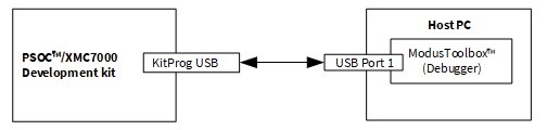
Bootloader is the first software to execute on the device which makes debugging straightforward similar to ordinary applications. To debug a bootloader, you can directly connect the kit and initiate the debug session. See the
Eclipse IDE for ModusToolbox™ user guide
for details. Note that the bootloader here could be either DFU MW-based bootloader or any other bootloader (such as MCUboot-based bootloader, etc.). However, the concept remains the same.
Debugging the application:
For debugging the end application, you need to attach the debugger to the application. The debug session starts when the execution of the end application starts after the bootloader passes the execution to the application. To attach a debugger to the application, do one of the following. See the
Eclipse IDE for ModusToolbox™ user guide
for more details.
Use the "modus shell" terminal from the application directory and use the
make attach_proj
command.
Select
Attach configuration
from ModusToolbox™ Debug launches.
Debugging DFU middleware-based project
A DFU-based project can be a bootloader or application. This section is applicable in either of the cases unless specified otherwise, as long as the conditions and steps specified in
Debugging firmware update solution
are taken care of. Depending on the use of DF MW in the project, the developer needs to perform special steps to debug a particular project as described in this section.
Typically, debugging involves; step-into the code using the debugger and observing the serial console messages. In several cases, it is sufficient to do either of the processes. However, it might be required to do both in a few scenarios to get the best out of the debug process.
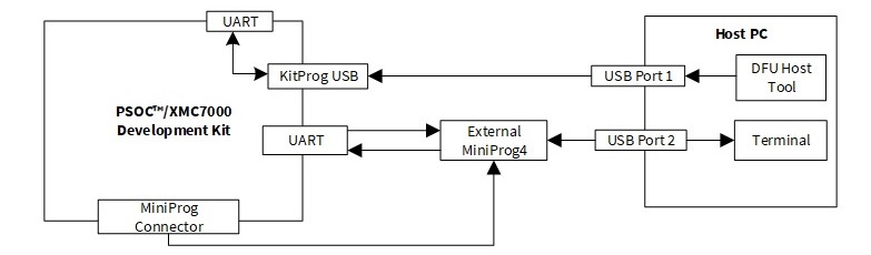
Figure 17.
DFU MW debug setup
shows the debug setup to debug the DFU MW-based application in Linux and macOS platforms, but this setup will not help debug applications on the Windows platform because of the limitation of the WinUSB driver as described below.
DFU MW-based applications which use the transport interface to communicate with the host generally use KitProg for receiving the command and data for the required operation to be performed. In KitProg version 2.10 and newer, bridging is implemented on bulk endpoints for improved performance over I2C/SPI. However, Windows cannot use the USB-I2C/SPI bridging interface and the CMSIS-DAP bulk interface at the same time because of a WinUSB driver limitation. Therefore, the typical way of using the KitProg3 for debugging and receiving UART logs is not feasible because of using the same channel as the transport.
For debugging the DFU MW bootloader with transport, you need to use an external MiniProg4 programmer/debugger for debugging the bootloader application and an existing KitProg connection for using the transport simultaneously. Logs can be included in the application software to dump the execution-runtime device data to the console connected to the device using the same setup. Connect the MiniProg4 using the 10-pin connector. For more details, see the
CY8CKIT-005 - MiniProg4 Program and Debug Kit guide
.
To start a debug session, do the following:
Open the device configurator/kit guide. Check for available free SCBs and UART pins.
Connect the UART pins to the TX-RX pair of MiniProg.
Provide the pin details to the retarget-io initialization in the source file.
Build and program the DFU application
Connect the external MiniProg4 connector to the kit.
Power ON MiniProg4 using
ModusToolbox™ Programmer GUI user guide
.
Open ModusToolbox™ and start the debug session.
Connect the USB with the onboard KitProg port.
In the debug window, start a free run of the application.
Open the DFU Host Tool and select the KitProg interface.
Click
Program
and
debug
simultaneously using debug session with MiniProg4.
shows the typical setup and external connection for debugging the application while performing DFU and receiving console logs at the same time.
Figure 18.
DFU MW console logs setup
You can use the debug session to monitor the device. However, using the transport communication during step debugging or breakpoint results in the timeout of either your device or the DFU Host Tool at the host machine. This leads to force failure of the communication link between the target and the host. To debug the device while communicating with the host, modify the timeout at the host tool installed on the host machine and in the application software.
Timeout configuration at the target side consists of multiple macros for various timeout parameters as follows:
DFU_SESSION_TIMEOUT_MS:
This macro provides the timeout in milliseconds to complete a particular command session, which indicates the transport layer communication started must be finished within the specified timeout.
DFU_COMMAND_TIMEOUT_MS:
This macro is used for the timeout parameter for the waiting period between the two commands. It indicates that the DFU MW at the device expects the next command within the time period specified in milliseconds, failing to which may lead to device timeout and restarting of the whole transport.
DFU_IDLE_TIMEOUT_MS:
This macro provides the time period in milliseconds for which the DFU MW waits for the first command because set up the transport layer for the communication link between the host and the device.
To modify the timeout period on the device side, you can modify these macros according to the requirement to prevent the force reset of the communication channel. To modify the host timeout and other configurations on the host side, see the
ModusToolbox™ DFU Host tool user guide
.
Debug DFU middleware-based bootloader
The DFU MW application project consists of two separate applications; the bootloader project and the end application. A DFU MW-based bootloader uses a custom method to switch to the application by triggering a soft reset and scheduling the execution of the application before the soft reset.
The DFU MW uses a custom
Cy_OnResetUser()
function for reset handling; i.e., to transfer control to the respective application as scheduled before triggering the reset. Call this function by the bootloader application’s reset handler before executing the main routine of the bootloader. Therefore, this creates a potential issue while debugging because the debugger expects the main routine to execute.
To debug a bootloader based on the DFU MW, comment out the
Cy_OnResetUser()
function from the bootloader to directly start the execution from the
main()
for step debugging and prevent unexpected behavior while debugging.
DFU Host Tool
The DFU Host Tool (DHT) is a standalone graphical tool provided with ModusToolbox™. This tool communicates with the device that has a DFU MW-based application installed. Do the following to install the tool:
Download and install an application to a device
Verify an application that is already installed on a device
Erase an application from a device
Send
miscellaneous
commands to the device
Note:
You cannot use the DHT to install an application directly into the device. Instead, you must program a compatible application to the device SWD/JTAG port using other tools such as ModusToolbox™ or Infineon Programmer. After a DFU MW-based application is installed, you can use the DHT to install a downloadable application.
The DFU Host Tool supports communicating with MCU devices via UART, I2C, SPI,
CAN FD,
or USB as shown in
Figure 19
. You can see all devices available for connection. For UART or USB, communication can be done directly from your computer by connecting a USB cable. For I2C and SPI, a special communication port such as a KitProg module is required. The port configuration fields change depending on the selected port.
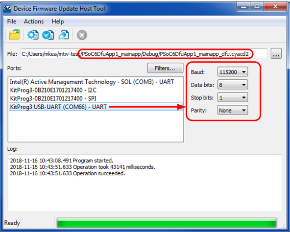
Figure 19
shows the typical GUI of the
ModusToolbox™ DFU Host tool user guide
.
Note:
Currently, only the UART, I2C, and SPI-based DFU are supported for PSOC™ 4 and PSOC™ 6.
Figure 19.
DFU Host Tool GUI
Host command/response protocol
The DFU module communicates with a host using a simple command-response protocol, regardless of the communication channel used. The DFU module receives commands from the communication channel and responds to each command by sending one or more bytes to the communication channel. See
Figure 4
.
The commands and responses are in the form of a byte stream, packetized to ensure the integrity of the data being transmitted. A packet validity check method is included and consists of a 2's complement 16-bit checksum.
Command/response packet structure
Communication packets sent from the host to the DFU module have the structure shown in
Figure 20
:
Figure 20.
DFU command packet structure
Response packets sent from the DFU module to the host have the structure shown in
Figure 21
:
Figure 21.
DFU response packet structure
All multi-byte fields are LSB first.
Standard DFU middleware commands
These include predefined commands available in the DFU core which uses the application to implement specific operations. Each command has a functionality defined in
dfu_user.c
, which handles the operation that the device performs when the following commands are received.
shows a list of commands supported by the DFU MW. All commands except
Exit DFU
are ignored until the
Enter DFU
command is received.
Command name | Command ID | Functionality |
|---|---|---|
0x38 | Starts a DFU session | |
0x35 | Synchronizes target and host | |
0x3B | Ends a DFU session | |
0x37 | Sends data to the device | |
0x47 | Sends data to the device without expecting a response | |
0x49 | Programs a row of data to the device | |
0x4A | Verifies the row of data | |
0x44 | Erases the row of flash | |
0x31 | Verifies the application available in flash | |
0x4C | Sets metadata for a given application | |
0x3C | Fetches metadata for application from flash | |
0x4D | Sets an EIV to use in decryption |
There is no specific requirement for command execution time.
lists all status and error codes supported by the DFU MW.
Status/error code | Value | Description |
|---|---|---|
CY_DFU_SUCCESS | 0x00 | Command successfully received and executed |
CY_DFU_ERROR_VERIFY | 0x02 | Verification of nonvolatile memory (NVM) after writing failed |
CY_DFU_ERROR_LENGTH | 0x03 | Amount of data sent is greater than expected |
CY_DFU_ERROR_DATA | 0x04 | Packet data is not of the proper form |
CY_DFU_ ERROR_CMD | 0x05 | Command not recognized |
CY_DFU_ERROR_CHECKSUM | 0x08 | Packet checksum or CRC does not match the expected value |
CY_DFU_ERROR_ROW | 0x0A | Flash row number is not valid |
CY_DFU_ERROR_ROW_ACCESS | 0x0B | Flash row numbers cannot be accessed, for example, because of MPU protection |
CY_DFU_ERROR_UNKNOWN | 0x0F | An unknown error occurred |
Enter DFU
This command starts a DFU operation. All other commands except Exit DFU are ignored until this command is received. This command responds with the device information and DFU MW version.
Input
Command byte: 0x38
Data bytes:
4 bytes (optional): Product ID. If these bytes are included and they are not 00 00 00 00, then they are compared to the device product ID data
Note:
Product ID data is optional when the DFU MW loader application does not specify the Product ID or it is defined as 00 00 00 00, only in mentioned scenario communication between the device and host does not require the product ID. On the other hand, if the DFU bootloader contains a hard-coded product ID, the communication between the host and device requires a specific product ID because the input data with the Enter DFU command is required to initiate the DFU session.
Output
Status/error codes:
Success
Error command
Error data used for product ID mismatch
Error length
Error checksum
Data bytes:
4 bytes: Device JTAG ID
1 byte: Device revision
3 bytes: DFU MW version
Note:
By default, the bootloader returns '0' for device revision. If required, modify by editing the macro
CY_DFU_SILICON_REV
in
cy_dfu.h
.
Sync DFU
This command resets the DFU to a known state, making it ready to accept a new command. Any data that is buffered is discarded. This command is required only if the DFU module and the host gets out of sync with each other.
Input
Command byte: 0x35
Data bytes: N/A
Output
N/A – This command is not acknowledged
Exit DFU
Send Data
This command transfers a block of data to the DFU module. This data is buffered in anticipation of a
Program Data
or
Verify Data
command. If a sequence of multiple
Send Data
commands is sent the data is appended to the previous block. This command breaks the large data transfers into smaller pieces to prevent channel starvation in some communication protocols.
Input
Command byte: 0x37
Data bytes:
n bytes: Data to write or verify
Output
Status/error codes:
Success
Error command
Error data
Error length
Error checksum
Data bytes: N/A
Send Data Without Response
Program Data
This command writes data to one row of the device’s internal flash or page of external nonvolatile memory (NVM). This follows a series of
Send Data
or
Send Data Without Response
commands.
Input
Command byte: 0x49
Data bytes:
4 bytes: Address. Must be within the correct memory address space and appropriately aligned. For internal flash, align to a flash row boundary. For external memory, it must conform to external memory alignment requirements.
4 bytes: CRC-32C of the entire data to be written. The data is verified both before and after programming.
n bytes: Data to write into the flash row or external NVM page.
Output
Status/error codes:
Success
Error command
Error data
Error length
Error checksum
Error flash row
Error flash row access
Data bytes: N/A
Verify Data
This command compares the data to one row of the device’s internal flash or page of SMIF. May follow a series of
Send Data
or
Send Data Without Response
commands.
This command is optional; its presence depends on a user configuration macro in
dfu_user.h
.
Input
Command byte: 0x4A
Data bytes:
4 bytes: Address. Must be within the correct memory address space and appropriately aligned. For internal flash, align to a flash row boundary. For external memory, confirm external memory alignment requirements.
4 bytes: CRC-32C of the entire data to be verified.
n bytes: Data to compare with the flash row or SMIF page.
Output
Status/error codes:
Success
Error verify
Error command
Error data
Error length
Error checksum
Error flash row
Error flash row access
Data bytes: N/A
Implementation details:
The command returns the "Success" status code if all data bytes match the bytes starting at the specified flash address; otherwise "Error Verify".
Erase Data
This command erases the contents of the specified internal flash row or SMIF page.
This command is optional; its presence depends on a user configuration macro in
dfu_user.h
.
Input
Command byte: 0x44
Data bytes:
4 bytes: Address. Must be within the correct memory address space and appropriately aligned. For internal flash, align to a flash row boundary. For external memory, confirm external memory alignment requirements.
Output
Status/error codes:
Success
Error command
Error data
Error length
Error checksum
Error flash row
Error flash row access
Data bytes: N/A
Verify application
This command reports whether the checksum for the application in flash or external NVM is valid.
Input
Command byte: 0x31
Data bytes:
1 byte: Application number of the application to be verified. May range from 0 to the number of applications minus one.
Output
Status/error codes:
Success
Error command
Error data
Error length
Error checksum
Error flash row access
Data bytes:
1 byte: 1/0 for application is valid or not valid
Set Application Metadata
This command sets a given application’s metadata. See
Appendix A: Application metadata
.
Note:
This command does not update the metadata if the user configures the DFU MW to keep the metadata unchanged.
Input
Command byte: 0x4C
Data bytes:
1 byte: Application #
8 bytes: Metadata field format per
Appendix A: Application metadata
Output
Status/error codes:
Success
Error command
Error length
Error data
Error checksum
Error flash row access
Data bytes: N/A
Get Metadata
This command reports the selected metadata bytes.
This command is optional; its presence depends on a user configuration macro in
dfu_user.h
.
Input
Command byte: 0x3C
Data bytes:
2 bytes: From offset within a row; 0 – 511
2 bytes: To offset within a row; 0 – 511 (inclusive)
Output
Status/error codes:
Success
Error command
Error length
Error data
Error checksum
Error flash row access
Data bytes:
N bytes – Per from and to offset bytes (inclusive)
Set EIVector
This command sets an encryption initialization vector (EIV). This enables the DFU module to decrypt the data before writing it to flash.
This command is optional; its presence depends on a user configuration macro in
dfu_user.h
.
Input
Command byte: 0x4D
Data bytes:
n bytes: Vector; 0, 8, or 16 bytes, little-endian raw data
Output
Status/error codes:
Success
Error command
Error length
Error data
Error checksum
Data bytes: N/A
DFU MW user-defined command
DFU MW provides various commands to execute certain operations, such as reading, erasing, and programming the flash, as well as functions, such as synchronizing the target and host, and sending data to the host, as discussed in the
Standard DFU middleware commands
section. Apart from the basic commands, DFU MW also supports user-defined commands to allow for custom operations on the device.
The application is responsible for handling these user-defined commands using the custom handler. Typically, the application registers a single handler and the user needs to develop the parsing logic to handle the required user-defined command at the device. The application can combine all command handling inside the registered handler and execute accordingly. Alternatively, it can use multiple handlers for separate commands and call them as per the command requirement.
The application can use the DFU MW API to register the single handler using the
Cy_DFU_RegisterUserCommand()
API. If a user command is received at the device, DFU MW calls the registered handler. The register handler should handle the respective command, either by combining all handling operations or by calling the respective handlers for the user command. Similarly,
Cy_DFU_UnRegisterUserCommand()
can be used to unregister the user handler for the user-defined command.
The user needs to define a custom command handler in either the project
main.c
or the
dfu_user.c
. The handler should parse the command to handle according to the command ID extracted from the incoming command packet, along with the data extracted with the command to perform operation as defined in the handler as per command ID. It should also provide the respective status and output response data according to the operation requested by the host. The command and response follows the standard DFU packet structure shown in section
Host command/response protocol
.
DFU MW provides the following commands to add user-defined commands support to an existing application:
CY_DFU_OPT_CUSTOM_CMD
macro allows to enable/disable user-defined command feature during build time. This macro is disabled by default. If you want to add your own 'user-defined' commands, set this macro to '1' during build
Cy_DFU_RegisterUserCommand
function can be used to add a custom handler for user-defined command
Users can define their own custom handler function for user-defined commands, which enables the implementation of command-specific handling as per the end use case. To register a user-defined command, call the following function with an appropriate command handler function defined by the user
Cy_DFU_RegisterUserCommand
(
&
dfu_params
,
handler
)
;
In the above code snippet, the
dfu_params
is an active DFU param structure and the handler is a function pointer to the user-defined command handler
Response structure limits the maximum number of commands to "256" (8 bits). Therefore, “244” user-defined commands can be added included in the solution
Command area
0x00-0x4F
is reserved for DFU
Command area
0x50-0xFF
is reserved for user-defined commands
Users can define the custom handler function for user-defined commands that enables the implementation of command-specific handling as per the end use case
Cy_DFU_UnRegisterUserCommand
function call can be used for unregistered handler
File formats
DFU Host Tool supports the following file formats that you can leverage:
.cyacd2
format: This is a legacy file format for input image. It contains the firmware image data in ASCII format. This format can be used only for legacy device families such as PSOC™ 6 and PSOC™ 4 MCUs.
.mtbdfu
format: This is a JSON-based newly introduced file format for all other future product families and legacy devices as required.
This section discusses the details of both file formats, describes how to generate the input files, and specifies the important information required to generate these files. The JSON format support is the default execution; depending on the use case, you can use JSON (
.mtbdfu
extension) or
.cyacd2
file for the solution.
.cyacd2 file format
The
.cyacd2
file contains the downloadable application data. It is generated by the ‘CyMCUElfTool’ tool and is used by host programs such as Infineon’s
DFU Host Tool
to send applications to the target DFU module, as shown in
Figure 1
. The file data is in the form of ASCII hex numbers, similar to the Intel hex format. Each byte of data is represented by two characters.
For example, a byte 0x1E is represented by the characters 0x31 (ASCII ‘1’) followed by 0x45 (ASCII ‘E’).
All multi-byte fields are little-endian. The file consists of a series of lines or rows. Each row is terminated with ASCII CR and LF characters. A row is one of the following types:
Encryption initial vector:
This row is of the format @EIV:<bytes>. The data in <bytes> is used by the host program in the
Set EIVector
to the DFU module.
Application verification information:
This row is of the format:
@APPINFO:[__cy_app_verify_start],[__cy_app_verify_length]The start and length data are used by the host program in the
Set Application Metadata
to the DFU module
Header:
A header row has the structure shown in
Table 9
.
Table 9.
cyacd2 header row structure
File version
Silicon ID
Silicon revision
Checksum type
App ID
Product ID
1 byte
4 bytes
1 byte
1 byte
1 byte
4 bytes
File version:
Numbered starting at 1
Silicon ID, Silicon Revision:
To prevent the application from being downloaded to an incorrect device
Note:
By default, the bootloader returns ‘0’ for Silicon ID and Silicon Revision. If required, modify them by changing the macros
CY_DFU_SILICON_ID
and
CY_DFU_SILICON_REV
in
cy_dfu.h
Checksum type:
The method used to verify a DFU packet (see
Host command/response protocol
). 0 = checksum, 1 = CRC
App ID:
See
Table 9
. This also controls which portion of the application metadata is updated for this application
Product ID:
A unique ID acts as an identifier to prevent the flashing of incorrect application images to the device. Modify by changing the
__cy_product_id
variable in the application linker script or Makefile as applicable
Note:
The product ID must be the same as the product ID (
__cy_product_id
) in the bootloader’s linker script to ensure successful verification
Data:
A data row has the structure shown in
Table 10
.
The value of 'N' equals the total amount of data to be sent with a series of
Send Data
or
Send Data Without Response
commands followed by
Program Data
or
Verify Data
commands
The value of 'N' typically, but not necessarily, equals the length of an NVM row. For example, if downloading into the RAM, ‘N’ may be an arbitrary value
Table 10.
cyacd2 data row structure
Header
Address
Data
1 character: ":"
4 bytes
N bytes
JSON format
The DFU Host Tool supports JSON format as the input file with the .mtbdfu extension. It uses a JSON parser to extract the required information to generate the DFU command format for sending to the device. The JSON (
.mtbdfu
) file expects the set of commands to be executed along with the attributes like data, and offset for the address to be written.
Code Listing 1
shows the typical format of the JSON file to be provided as the input to the host tool; it consists of two sections:
APPInfo:
Contains the application and device-specific configuration information
Command:
Consists of the command and data-specific details to be transferred.
Table 11
lists the basic fields required in the command section in JSON format.
Code Listing 1 JSON format
{
"APPInfo": {
 "File Version": "0x1",
 "Packet Checksum Type": "0x0",
 "Product Id": "01020304"
},
"commands": [
 {
     "commandSet": [
         {
             "cmdId": "0x37",
             "dataLength": "0x10",
             "repeat": "0x20"
         },
         {
             "cmdId": "0x49",
             "dataLength": "0x08"
         }
     ],
     "dataFile":"blinky_cm4_crc.hex",
     "flashRowLength": "0x200",
     "repeat": "EoF"
 }
]
}
The AppInfo section consists of information about the device and the application
File version:
Indicates the application version; can be used to track updates
Product ID:
Unique ID of the device communicating with the host
Checksum type:
Checksum type to be used for hex; for image validation
The command section consists of the details of the command to be sent to the device along with the data. The following table lists the fields available in the command section.
Field | Description |
|---|---|
cmdId | Command field. Specifies the DFU command number; the valid range is 0x00 - 0xFF. [0x00 - 0x49]: Standard DFU command range [0x50-0xFF]: Reserved for Future Use |
dataBytes | (Optional) Actual payload data to be used in the command. |
dataFile | (Optional) Specifies the name of the Input file from where the payload data has to be read. |
dataLength | (Optional) Length of the payload data in bytes |
outfile | (Optional) Specifies the file name to store intermediate packets generated by the tool. |
repeat | Repeats the command for a specified number of times. Valid only if the “dataFile” is defined. For example: Repeat: “10” means repeat the command 10 times. Repeat: “EoF” means repeat the command until the end of the data file. |
flashRowLength | Specify the flash row length on the device. Valid only if the “dataFile” is defined. |
Note:
The APPInfo section is mandatory for the JSON file; it is required to start the DFU communication.
Define the optional commands based on the use case.
The
.mtbdfu
file supports multiple fields apart from above mentioned. For more details, see the
ModusToolbox™ DFU Host tool user guide
.
Code examples
There are code examples associated with this application note. They demonstrate the different ways that DFU operations can be executed; see
Table 2
.
A complete list of code examples and other documents are available on
infineon.com
and also in
References
.
shows an overview-level list of the code examples:
CE # | Title | Description |
|---|---|---|
Supports ModusToolbox™ IDE | ||
PSOC™ 6 MCU: Basic Device Firmware Upgrade (DFU) |
| |
PSOC™ 4: Basic Device Firmware Upgrade (DFU) |
| |
XMC7000: OTW firmware upgrade |
| |
CE240598 | PSOC™ Control C3: OTW firmware upgrade |
|
CE240679 | PSOC™ Control C3: Live firmware upgrade |
|
Generally, all applications are in the same workspace in Eclipse IDE for ModusToolbox™. As noted in
Developing DFU applications in ModusToolbox™
, projects can exist in separate workspaces as well as in separate locations on your computer.
Appendix A: Application metadata
Note:
This section is not applicable for
PSOC™ Edge
device.
The DFU MW uses a designated region of NVM (or RAM in a few cases) to store information about the applications – see
Using the DFU middleware
. Generally, metadata information is used for the following purposes:
Validate an application
Transfer control from one application to another
Copy an application image from a temporary location to its designated location
Note:
Application metadata section is required only when the DFU MW is used to design the bootloader. With MCUboot bootloader flow, the metadata section is not required.
As noted in
Using the DFU middleware
, the metadata typically occupies one flash row or an NVM page (in devices with small amounts of flash, multiple rows or pages may be used).
Using the DFU middleware
also shows that metadata is located outside of any application.
contains symbols to define the location, size, and usage of the DFU metadata. The symbols are defined in the MW linker script and C source files.
Note:
All examples shown are for the GCC compiler and linker. Similar statements exist in source and linker script files for the MDK and IAR compilers and linkers.
Symbol | Defined In | Purpose |
|---|---|---|
flash_boot_meta | dfu_cm0p.ld , dfu_cm4.ld | Defines the physical memory region that contains the metadata |
Example usage: Defines a region in the last 1 KB of the 1-MB PSOC™ 6 MCU user flash (which starts at 0x1000 0000). | ||
__cy_boot_metadata_addr
| dfu_cm0p.ld , dfu_cm4.ld | These symbols define a compiler-independent memory address range that uses to store the metadata. These symbols are used in the DFU MW and user codes. |
Example usage: /* Bootloader MW metadata limits */ /* Note that __cy_memory_0_row_size equals the row length in bytes of PSOC™ 6 user flash. */
| ||
.cy_boot_metadata | dfu_cm0p.ld , dfu_cm4.ld | The DFU metadata is stored in this section. At build time, CyMCUElfTool calculates the checksum of this section and places it in the last four bytes of the section. When a checksum is not required, rename the section to any other name. |
Example usage:
| ||
CY_DFU_MAX_APPS | dfu_user.h | Allows the user to control the maximum number of applications supported in the DFU metadata |
Example usage: /* The smallest metadata size is CY_DFU_MAX_APPS * 8 bytes per app + an optional 4 bytes for metadata checksum */
| ||
CY_DFU_METADATA_WRITABLE | dfu_user.h | The DFU does not necessarily write metadata – it can be done by the application or some other user code, or the metadata may be set using a compile-time constant within an application. An application can have metadata that is smaller than an NVM row. In all these cases, set this macro to ‘0’ to prevent the DFU from writing the metadata. However, note that the DFU requires that a metadata region to exist and be properly initialized. This may be done by the DFU itself or by an application. |
Example usage: /* A non-zero value allows writing metadata with the command. */ | ||
Appendix B: Metadata structure
The application metadata has eight bytes of data per application, followed by four bytes for checksum, as shown in
Figure 22
:
Figure 22.
Metadata structure
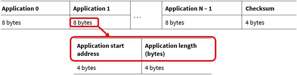
You can set the number of applications N in the dfu_user.h file:
#define CY_DFU_MAX_APPS (N)The default value of N is 2.
Align each application start address to a flash row or NVM page boundary. The application length must be a multiple of the flash row or NVM page length.
Calculate the checksum with the same algorithm that is used in the DFU commands
Program Data
and
Verify Data
. The default algorithm is CRC-32C.
Glossary
.cyacd2
Application file format that contains the firmware image for the target to be updated; it is generated by the ‘CyMCUElfTool’, and is used by DFU Host Tool to send the image to the target.
.mtbdfu
JSON-based Infineon-specific file extension for the input file to DFU Host Tool
Application
The binary image of the end application is stored in the flash during the update.
Bootloader
Software running on MCU, that is responsible for validating, installing, and launching next-stage applications.
CAN FD
Controller Area Network Flexible Data-Rate is an extension to the original CAN bus protocol developed by Bosch to increase the data transfer rate.
CRC
Cyclic Redundancy Check (CRC): It is an error-detecting code used to detect accidental changes to digital data.
Firmware
The software code executes on the MCU. The word firmware is used in general for bootloader and user applications.
HAL
Hardware Abstraction Layer: Set of driver libraries that can be used as the wrapper around the hardware layer; these provide hardware-independent API for using the hardware.
I2C
Inter-Integrated Circuit: A multi-master, multi-slave, single-ended, serial computer bus invented by Philips Semiconductor.
JSON
Java Script Object Notion: Lightweight format of storing and transporting data across the platform, it stores data in key-value pair format.
MW
Middleware: A SW Library that enables the distributed component layers to connect and communicate.
NVM
Nonvolatile Memory: It is a type of computer memory that can retain stored information even after power is removed. Here referred to the flash memory of MCU.
PDL
Peripheral Device Library: Set of driver libraries implemented with respect to the hardware to be used. Unlike HAL, they are strongly dependent on the hardware for implementation.
SPI
Serial Peripheral Interface: A serial interface bus used for communication with sensors, flash memory, RTC, etc.
UART
Universal Asynchronous Receiver Transmitter: A common serial interface used in PCs used for asynchronous serial communication.
USB
Universal Serial Bus: An industry specification for standardizing computer and peripheral communication, and Power Delivery.
USB CDC
Communication Device Class: Protocol which provides access to COM port through USB for Communication.
XIP
Execute-In-Place: Method of executing code directly from the serial Flash memory without copying the code to the RAM or any other internal memory of the device.
CyMCUELFTool
Infineon’s proprietary tool for generating .cyacd2 files.
References
Application notes
Infineon Technologies AG:
AN235935 – Getting started with PSOC™ Edge E84 on ModusToolbox™ software
Infineon Technologies AG:
AN237849 – Getting started with PSOC™ Edge Security
Infineon Technologies AG:
AN238329 – Getting started with
PSOC™ Control
C3 MCU on ModusToolbox�™ software
;
Available online
Infineon Technologies AG:
AN240106 – Getting started with
PSOC™ Control
C3 security
;
Available online
Infineon Technologies AG:
AN228571 – Getting started with PSOC™ 6 MCU on ModusToolbox™ software
;
Available online
Infineon Technologies AG:
AN215656 – PSOC™ 6 MCU dual-core system design
;
Available online
Infineon Technologies AG:
AN213924 – PSOC™ 6 MCU Device Firmware Update (DFU) software development kit guide
;
Available online
Infineon Technologies AG:
AN79953 – Getting started with PSOC™ 4 MCU
;
Available online
Development kits
Infineon Technologies AG:
CY8CKIT-062-BLE – PSOC™ 6 Bluetooth® LE Pioneer Kit
;
Available online
Infineon Technologies AG:
CY8CKIT-062-WiFi-BT – PSOC™ 6 Wi-Fi Bluetooth® Pioneer Kit
;
Available online
Infineon Technologies AG:
CY8CPROTO-063-BLE – PSOC™ 6 Bluetooth® LE Prototyping Kit
;
Available online
Infineon Technologies AG: CY8CPROTO-062-4343W – PSOC™ 6 Wi-Fi Bluetooth® Prototyping Kit;
Available online
Infineon Technologies AG:
CY8CKIT-041S-MAX – PSOC™ 4100S Max Pioneer Kit
;
Available online
Infineon Technologies AG:
CY8CKIT-149 – PSOC™ 4100S Plus Prototyping Kit
;
Available online
Infineon Technologies AG:
CY8CKIT-145-40XX – PSOC™ 4000S CAPSENSE™ Prototyping Kit
;
Available online
Infineon Technologies AG:
CY8CKIT-040T – PSOC™ 4000T CAPSENSE™ Evaluation Kit
;
Available online
Infineon Technologies AG:
KIT_PSOCE84_EVK – PSOC™ Edge E84 Evaluation Kit
Infineon Technologies AG:
KIT_PSC3M5_EVK – PSOC™ Control C3 Evaluation Kit
;
Available online
Tools
Infineon Technologies AG:
ModusToolbox™ software
;
Available online
Revision history
Document revision | Date | Description of changes |
|---|---|---|
** | 2023-05-05 | Initial release |
*A | 2023-07-31 | Added support for PSOC™ 4 and XMC7000 MCU family |
*B | 2024-03-05 | Fixed the links Removed Components datasheets section in References |
*C | 2024-09-26 | Template update; no content update |
*D | 2024-12-09 | Added support for PSOC™ Control C3 MCU and CAN FD support for XMC7000 |