AN238329 Getting started with PSOC™ Control C3 MCU on ModusToolbox software
About this document
Scope and purpose
This application note is to introduce the
PSOC™ Control C3
MCU, which is a single-core, high-performance, low-power, and secure MCU designed for real-time control, enhanced sensing, and secure and low-power applications. This application note helps you to explore the
PSOC™ Control C3
MCU architecture and development tools and shows you how to create your first project using the Eclipse IDE for ModusToolbox™ software. This application note also guides you to more resources available online to accelerate your learning about the
PSOC™ Control C3
MCU.
Intended audience
This document is intended for the users who are new to
PSOC™ Control C3
and ModusToolbox™ software.
Associated part family
All
PSOC™ Control C3
devices.
Software version
3.3 or above.
More code examples? We heard you.
To
access an ever-growing list of PSOC™ Control C3 code examples using ModusToolbox™, please visit the GitHub site
.
Introduction
The
PSOC™ Control C3
device is a microcontroller targeted at industrial applications. The
PSOC™ Control C3
integrates the following features on a single chip:
Single core 180 MHz 32-bit Arm® Cortex®-M33 CPU with
Floating-point unit (FPU)
DSP
Memory protection unit (MPU)
TrustZone framework support
16 KB I-cache
Up to 256 KB Read-While-Write Flash with ECC support
64 KB ROM for boot code
64 KB SRAM with ECC support
Industrial control peripherals: Coordinate rotation digital computer (CORDIC) and timer/counter pulse-width modulator (TCPWM) supporting high-resolution pulse-width modulator (HRPWM)
High-performance programmable analog subsystem (HPPASS): 12-bit, up to 12-Msps SAR ADC with parallel idle sampling of up to 16 analog channels and five comparators with <10 ns, built-in 10-bit DAC, and slope generator
ModusToolbox™ development environment with installable SDKs and libraries, industry standard Arm® tools, and RTOS support
This application note introduces you to the capabilities of the
PSOC™ Control C3
, gives an overview of the development ecosystem, and gets you started with a simple 'Hello World' application wherein you learn to use the
PSOC™ Control C3
. Additionally, it shows you how to create an application from an empty starter application. The completed design of this application is available as a
code example for ModusToolbox™ on GitHub
.
For hardware design considerations, see the Hardware design guide for the
PSOC™ Control C3
family.
Architecture and product lines
shows a detailed block diagram of the MCU.
Figure 1.
Functional block diagram
There are four variants in the
PSOC™ Control C3
.
Table 1
provides an overview of different product lines.
Product line | Device series | Details |
|---|---|---|
Entry line | PSC3P2x | Single-core 100 MHz Arm® Cortex®-M33, up to 256 KB flash and 64 KB RAM, 12-channel 6 Msps ADC |
PSC3M3x | Single-core 100 MHz Arm® Cortex®-M33, up to 256 KB flash and 64 KB RAM, 12-channel 6 Msps ADC, CORDIC, MOTIF | |
Main line | PSC3P5x | Single-core 180 MHz Arm® Cortex®-M33, up to 256 KB flash and 64 KB RAM, 12-channel 12 Msps ADC |
PSC3M5x | Single-core 180 MHz Arm® Cortex®-M33, up to 256 KB flash and 64 KB RAM, 12-channel 12 Msps ADC, CORDIC, MOTIF |
PSOC™ Control C3 features
PSOC™ Control C3
MCUs have extensive features as shown in
Figure 1
. The following is a list of major features. For more information, see the device datasheet, reference manuals, and
References
section.
CPU subsystem
Arm® Cortex®-M33 running up to
100 MHz
Digital signal processor (DSP), floating-point unit (FPU), memory protection unit (MPU), 16 KB I-cache
Two direct memory access (DMA) controllers with 16 channels each
Security
Platform security architecture level 2 (PSA L2) certified
Step-wise authentication of execution images until the control is handed over to the user code
Secure execution of code in the execute-only mode for protected routines
Image authentication and integrity check
TrustZone framework that establishes an isolated device root of trust (RoT) for trust attestation and software management
Memory
On-chip flash with ECC support
Up to 256-KB flash with read while write (RWW) capability, 64 KB ROM for boot code, and bootloader functions
Built-in device firmware upgrade (DFU) support in boot ROM via serial interface (UART/I2C/SPI)
SRAM with ECC support
64 KB
full SRAM available in Deep Sleep
SRAM data path is protected with a hardware mechanism (ECC) for soft error detection and correction
Clocking subsystem
8 MHz IMO with Deep Sleep operation offering ±2% accuracy
48 MHz internal high-frequency oscillator (IHO) offering ±1% accuracy
32 kHz internal low frequency oscillator (ILO) offering ±10% accuracy
4 to 35 MHz external crystal oscillator (ECO) support
32.768 kHz external watch crystal oscillator (WCO) usable for real-time clock (RTC)
External clock (EXTCLK): Maximum frequency 80 MHz
One frequency lock loop (FLL) with 24-100 MHz output range
Two digital phase-locked loops, DPLL#0 and DPLL#1, with 25-250 MHz output range
Low power (1.71 V to 3.6 V) operation
Six power modes (Active, Sleep, Deep Sleep, Deep Sleep-RAM, Deep Sleep-OFF, and Hibernate) for fine-grained power management
Deep Sleep mode current of 11 µA at 3.3-V external supply using an internal voltage regulator with 64-KB SRAM retention, LPComp, and Deep Sleep SCB
Hibernate mode current with RTC and LPComp of up to 1000 nA
Communication peripherals
Serial communication blocks (SCBs)
Up to six independent run-time-reconfigurable SCBs; each is software-configurable as I2C, SPI, or UART in master or slave mode
One SCB also supports Deep Sleep operation and wake-up from Deep Sleep in I2C slave and SPI slave modes
SCB supports single-wire half-duplex mode for UART
CAN FD
Up to two CAN FD channels with a single instance with operation of up to 8 Mbps
High-performance, programmable analog subsystem (HPPASS)
Analog-to-digital converter (ADC)
One 12-bit,
6-Msps
SAR ADC
Up to 16 dedicated analog pads, connected to up to 16 parallel sample stages
Two additional GPIOs can be used as analog inputs
Up to 16 sample/hold (S/H) circuits in SAR ADC connected to pins directly or through AMUX
One S/H circuit in SAR ADC is internally connected to analog references and a temperature sensor
Configurable input gain of 1, 3, 6, and 12 on all 16 S/H circuits
Digital comparator at the output to compare the ADC result against programmed boundary values
Digital comparator outputs can be connected to timer/counter pulse-width modulator (TCPWM) (low latency between the modules)
Analog comparators
Five Active comparators without Deep Sleep functionality, each with a 10-bit DAC to generate the comparator reference
Each comparator supports an external reference/threshold through pins
Active comparator can be used with the built-in DAC in Hysteresis mode
Two additional comparators in LPComp are available in Active/Deep Sleep/Hibernate modes
Comparator outputs can be brought to pins for control loop applications
Comparator outputs can be connected to TCPWM (low latency between the modules)
Logical OR of multiple comparator trigger outputs connected as an input trigger to TCPWM via trigger MUX
Real-time control peripherals
Coordinate rotation digital computer (CORDIC)
Supports all CORDIC operating modes for solving circular (trigonometric), hyperbolic functions, and integrated independent lookup tables to accelerate calculation
Timer/counter pulse-width modulator (TCPWM)
Sixteen 16-bit TCPWM channels
Four 32-bit TCPWM channels
Center-aligned, edge, and pseudorandom modes
Comparator-based triggering of kill signals
Shadow update of duty, period, dead-time, output signal polarity, and dithering (pseudorandom mode)
Multichannel control: In a group of eight TCPWM channels, one channel within a group can trigger another channel
Ability to logically combine the outputs of multiple channels through Smart I/O
Dedicated output triggers mux in a group to allow flexibility to the PWM channel as a trigger and/or gate signals to the HPPASS
Hall sensor interface with autonomous BLDC block commutation support
Quadrature encoder interface to decode motor speed and rotor position
I/O subsystem
Programmable GPIO pins
Up to
55
functional pins (
39
digital GPIOs; 2 out of
39
GPIOs can be used for analog inputs + 16 dedicated analog-only inputs)
Programmable drive modes, strengths, and slew rates
Programmable digital
Up to
six
Smart I/O capable ports (
22
I/Os, 56 LUTs) enable Boolean operations on I/O signals
Cryptography
Cryptography accelerator
Hardware acceleration for symmetric (AES-128) and asymmetric cryptographic algorithms (RSA and elliptic curve cryptography (ECC)) supported by vector unit (VU) and hash functions (SHA-256)
True random number generator (TRNG) function
Target applications
The versatile, secured, low-power, feature-rich offerings in the
PSOC™ Control C3
make it an ideal choice for a wide variety of end applications. Some of these applications are listed below.
The
ModusToolbox™ software
environment supports
PSOC™ Control C3
application development with a set of tools for configuring the device, setting up peripherals, and complementing your projects with world-class middleware. See the Infineon GitHub repos for board support packages (BSPs) for all kits, libraries for popular functionality like motor control and power stage converter, and a comprehensive array of example applications to get you started.
shows an application-level block diagram for a real-world use case using
PSOC™ Control C3
.
Figure 2.
Application-level block diagram using
PSOC™ Control C3
PSOC™ Control C3
is a highly capable and flexible solution for industrial applications. For example, the real-world use case in the
Figure 2
takes advantage of the following features:
TCPWM to drive the gates in the motor inverter and the power factor correction (PFC) circuit
ADC in the HPPASS for reading data from analog sensors
ADC in the HPPASS for reading the analog feedback, such as voltage and currents from the motor inverter and PFC circuit
CORDIC peripheral to do the mathematical operations used in motor control application
LPCOMP to compare the analog signals for protection
Inbuilt security features for firmware protection
Serial communication blocks (SCBs) to interface with external devices like motion sensors
Programmable Smart I/O to implement CPU independent simple logical operations on internal/external inputs
CAN FD channels to communicate with CAN FD capable peripherals
PSOC™ Control C3 resources
A wealth of technical resources is available to develop applications with the
PSOC™ Control C3
. These resources are listed below.
Overview
:
PSOC™ Control C3
webpage
Product selectors
:
PSOC™ Control C3
Entry line datasheet
and
main line datasheet
describes each device family and provides electrical specifications
Application notes
and
code examples
cover a broad range of topics, from basic to advanced level. You can also browse our collection of code examples
Reference manuals
(architecture and register) provide detailed descriptions of the architecture and registers in each device family
Development tools
: Many low-cost kits are available for evaluation, design, and development of different applications using
PSOC™ Control C3
s
Training videos
: Video training on our products and tools, including
PSOC™ Control C3
Technical support
:
PSOC™ Control C3
community forum
PSOC™ Control C3 development kits
Infineon provides a wide variety of hardware development kits in various form factors and features to enable easy and rapid evaluation and prototyping of
PSOC™ Control C3
based applications.
The following table lists the
PSOC™ Control C3
kits with various features.
ModusToolbox™ software is the software development platform for creating embedded applications using the development kits.
Kit MPN | Product | Kit name | BSP GitHub repo |
|---|---|---|---|
KIT_PSC3M5_EVK | PSC3M5xD | PSOC™ Control C3M5 Evaluation Kit | BSP |
KIT_PSC3M5_MC1 | PSC3M5xD | PSOC™ Control C3M5 Complete System Motor Control Kit | BSP |
KIT_PSC3M5_CC2 | PSC3M5xD | PSOC™ Control C3M5 Motor Drive Control Card | BSP |
KIT_PSC3M5_DP1 | PSC3M5xD | PSOC™ Control C3M5 Complete System Dual Buck Evaluation Kit | BSP |
KIT_PSC3M5_CC1 | PSC3M5xD | PSOC™ Control C3M5 Digital Power Control Card | BSP |
For the complete list of kits for the
PSOC™ Control C3
along with the shield modules, see the
PSOC™ Control C3
webpage.
PSOC™ Control C3 ecosystem for firmware/application development
Infineon provides the ModusToolbox™ software for firmware/application development on
PSOC™ Control C3
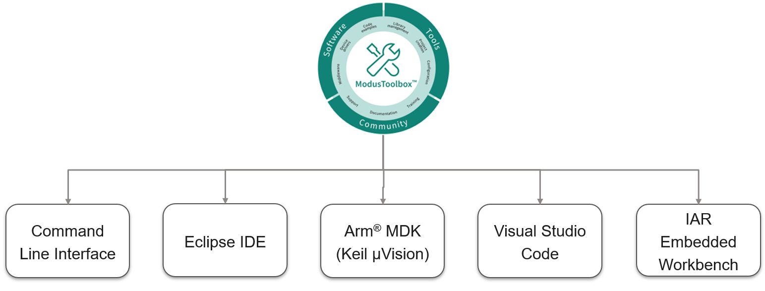
MCUs. ModusToolbox™ Software is a modern, extensible development ecosystem supporting a wide range of Infineon microcontroller devices, including PSOC™ Arm® Cortex® Microcontrollers, TRAVEO™ T2G Arm® Cortex® Microcontroller, XMC™ Industrial Microcontrollers, AIROC™ Wi-Fi devices, AIROC™ Bluetooth® devices, and USB-C Power Delivery Microcontrollers. This software includes configuration tools, low-level drivers, middleware libraries, and other packages that enable you to create MCU and wireless applications. All tools run on Windows, macOS, and Linux. ModusToolbox™ includes an Eclipse IDE, which provides an integrated flow with all the ModusToolbox™ tools. Other IDEs such as Visual Studio Code, IAR Embedded Workbench and Arm® MDK (μVision) are also supported.
ModusToolbox™ software
supports stand-alone device and middleware configurators. Use the
configurators to set the configuration of different blocks in the device and
generate code that can be used in firmware development.
Libraries and enablement
software are available at the GitHub site.
ModusToolbox™ tools and resources can also be used on the command line. See the build system chapter in the
ModusToolbox™ tools package user guide
for detailed documentation.
Installing the ModusToolbox tools package
Choosing an IDE
ModusToolbox™ software, the latest-generation toolset, is supported across Windows, Linux, and macOS platforms. ModusToolbox™ software supports 3rd-party IDEs, including the Eclipse IDE, Visual Studio Code, Arm® MDK (μVision), and IAR Embedded Workbench. The tools package includes an implementation for all the supported IDEs. The tools support all
PSOC™ Control C3
s. The associated BSP and library configurators also work on all three host operating systems.
Figure 3.
ModusToolbox™ environment
ModusToolbox help
The ModusToolbox™ ecosystem provides documentation and training. Launch the Eclipse IDE for ModusToolbox™ software and navigate to the following Help menu items:
Choose
Help > ModusToolbox™ General Documentation
:
ModusToolbox™ Documentation Index
: Provides brief descriptions and links to various types of documentation included as part of the ModusToolbox™ software
ModusToolbox™ Installation Guide
: Provides instructions for installing the ModusToolbox™ software
ModusToolbox™ User Guide
: This guide primarily covers the ModusToolbox™ aspects of building, programming, and debugging applications. Additionally, it covers various aspects of the tools installed along with the IDE
ModusToolbox™ Training Material
: Links to the training material available at
Release Notes:
Describes the features and known limitations for the ModusToolbox™ software, provided as part of the ModusToolbox™ tools package included with the installer
For documentation on Eclipse IDE for ModusToolbox™, choose
Help > Eclipse IDE for ModusToolbox™ documentation
.
User Guide
: Provides descriptions about creating applications as well as building, programming, and debugging them using Eclipse IDE
Eclipse IDE Survival Guide:
This is a link to a forum with answers for questions about how to get common tasks done
Getting started with PSOC™ Control C3 design
This section
does
the following:
Demonstrate how to build a simple
PSOC™ Control C3
-based design and program
into
the development kit
Makes it easy to learn
PSOC™ Control C3
design techniques and how to use the ModusToolbox™ software with different IDEs.
Prerequisites
Before you get started
with the application development instructions
, make sure that you have the appropriate development kit for your
PSOC™ Control C3
product line and have installed the required software. You also need internet to access the GitHub repositories during project creation.
Hardware
The following design example is developed for the
PSOC™ Control C3M5
Evaluation Kit (KIT_PSC3M5_EVK)
. However, you can build the application for other development kits also. For more details, see the section
Application development instructions
.
Software
3.3 or above.
After installing the software, see the
ModusToolbox™ tools package user guide
to get an overview of the software.
Application development instructions
These instructions are grouped into several sections. Each section is dedicated to a phase of the application development workflow. The major sections are:
Create a new application
View and modify the design
Write firmware
Build the application
Program the device
Test your design
This design is developed for the
PSOC™ Control C3M5
Evaluation Kit
. You can use other supported kits to test this example by selecting the appropriate kit while creating the application.
About the design
This design uses the
PSOC™ Control C3
to execute two tasks: UART communication and LED control.
After device reset, the CPU uses the UART to print a "Hello World" message to the serial port stream and starts blinking the user LED on the kit. When you press the 'Enter' key on the serial console, the blinking of the LED is paused or resumed.
Create a new application
This section takes you on a step-by-step guided tour of the new application creation process. It uses the
Empty App
starter application and manually adds the functionality from the
Hello World
starter application.
As mentioned in section
Choosing an IDE
, ModusToolbox™ software supports the following third-party IDEs:
The following sections provide details on how to create a new application on different IDEs.
Eclipse IDE for ModusToolbox
If you are familiar with developing projects with ModusToolbox™ software, you can use the
Hello World
starter application directly. It is a complete design, with all the firmware written for the supported kits. You can walk through the instructions and observe how the steps are implemented in the code example.
If you start from scratch and follow all the instructions in this application note, you can use the
Hello World
code example as a reference while following the instructions.
Launch the
Dashboard 3.3
application to get started.
Note:
Dashboard 3.3
application needs access to the internet to successfully clone the starter application onto your machine.
The
Dashboard 3.3
application helps you get started using the various tools with easy access to documentation and training material, a simple path for creating applications and creating and editing BSPs.
Open the Dashboard 3.3 application.
To open the
Dashboard 3.3
application, do one of these:
Windows:
Navigate to
[ModusToolbox installation path]/tools_3.2/dashboard/dashboard.exe
[ModusToolbox installation path]/tools_3.3/dashboard/dashboard.exe
or you can also select the "
dashboard
ModusToolbox™ Dashboard 3.3
" item from the Windows Start menu.
Linux:
[ModusToolbox installation path]/tools_3.2/dashboard and run the executable
[ModusToolbox installation path]/tools_3.3/dashboard and run the executable
macOS:
Run the "dashboard" app
On the Dashboard 3.3 window, in the right pane, in the Target IDE drop-down list, select Eclipse IDE for ModusToolbox™, and click Launch Eclipse IDE for ModusToolbox™.
Figure 4.
Dashboard 3.3
application
Select a new workspace.
At launch, Eclipse IDE for ModusToolbox™ displays a dialog to choose a directory for use as the workspace directory. The workspace directory is used to store workspace preferences and development artifacts. You can choose an existing empty directory by clicking the
Browse
button, as shown in the following figure. Alternatively, you can type in a directory name to be used as the workspace directory along with the complete path, and the IDE will create the directory for you.
Figure 5.
Select a directory as the workspace
- Create a new ModusToolbox™ application.
Click New Application in the Start group of the Quick Panel.
Alternatively, you can choose , as Figure 6 shows. Displays the Eclipse IDE for ModusToolbox™ Application window.
Figure 6.
Create a New ModusToolbox™ Application
- Select a target PSOC™ Control C3M5Evaluation Kit.
ModusToolbox™ speeds up the development process by providing BSPs that set various workspace/project options for the specified development kit in the new application dialog.
In the Choose Board Support Package (BSP)dialog, choose the Kit Name that you have. The steps that are followed use KIT_PSC3M5_EVK, as shown in Figure 7.
Click Next.
Figure 7.
Choose target hardware
In the Select Application dialog, select Empty App starter application, as shown in the following figure.
In the Name field, type in a name for the application, such as Hello_World. You can choose to leave the default name if you prefer.
Note:
Try to use a short name without spaces in between.
Click Create to create the application, as shown in the following figure, wait for the Project Creator to automatically close once the project is successfully created.
Figure 8.
Choose starter application
You have successfully created a new ModusToolbox™ application for a
PSOC™ Control C3
.
The BSP uses
PSC3M5FDS2AFQ1
as the default device that is mounted on the
PSOC™ Control C3M5
Evaluation Kit.
If you are using custom hardware based on the
PSOC™ Control C3
or a different
PSOC™ Control C3
part number, see the "Creating your Own BSP" section in the
ModusToolbox™ user guide
.
View and modify the design
shows the ModusToolbox™ project explorer interface displaying the structure of the application project.
PSOC™ Control C3
has one CM33 core. This application note shows the firmware development using the CM33 core with ModusToolbox™.
Figure 9.
Project Explorer view
A project folder consists of various subfolders – each denoting a specific aspect of the project.
The files provided by the BSP are in the bsps folder and are listed under TARGET_<bsp name> subfolders. All the input files for the device and peripheral configurators are in the config folder inside the BSP. The GeneratedSource folder in the BSP contains the files that are generated by the configurators and are prefixed with cycfg_. These files contain the design configuration as defined by the BSP. From ModusToolbox™ 3.x or later, you can directly customize configurator files of BSP for your application rather than overriding the default design configurator files with custom design configurator files since BSPs are completely owned by the application.
The BSP folder also contains the linker scripts and the start-up code for the
PSOC™ Control C3
used on the board.
The build folder contains all the artifacts resulting from a build of the project. The output files are organized by target BSPs.
The
deps
folder contains
.mtb
files, which provide the locations from which ModusToolbox™ pulls the libraries that are directly referenced by the application. These files typically each contain the GitHub location of a library. The
.mtb
files also contain a git Commit Hash or Tag that tells which version of the library is to be fetched and a path as to where the library should be stored locally.
For example, here, retarget-io.mtb points to
mtb://retarget-io#latest-v1.X#$$ASSET_REPO$$/retarget-io/latest-v1.X
. The variable $$ASSET_REPO$$ points to the root of the shared location which defaults to
mtb_shared
. If the library must be local to the application instead of shared, use $$LOCAL$$ instead of $$ASSET_REPO$$.
The libs folder also contains .mtb files. In this case, they point to libraries that are included indirectly as a dependency of a BSP or another library. For each indirect dependency, the Library Manager places a .mtb file in this folder. These files have been populated based on the targets available in deps folder.
For example, using BSP
KIT_XMC72_EVK
populates
libs
folder with the following
.mtb
files:
cmsis.mtb
,
core-lib.mtb
,
core-make.mtb
,
mtb-hal-cat1.mtb
,
mtb-pdl-cat1.mtb
,
cat1cm0p.mtb
,
recipe-make-cat1a.mtb
.
For example, using BSP KIT_PSC3M5_EVK populates the libs folder with the following
.mtb
files:
cmsis.mtb
,
core-lib.mtb
,
core-make.mtb
,
deivce-db.mtb
,
mtb-hal-psc3.mtb
,
mtb-pdl-cat1.mtb
,
receipe-make-cat1b
.
The
libs
folder contains the file mtb.mk, which stores the relative paths of all the libraries required by the application. The build system uses this file to find all the libraries required by the application.
Everything in the libs folder is generated by the Library Manager so you should not manually edit anything in that folder.
An application contains a Makefile which is at the application's root folder. This file contains the set of directives that the make tool uses to compile and link the application project. There can be more than one project in an application. In that case there is a Makefile at the application level and one inside each project.
By default, when creating a new application or adding a library to an existing application and specifying it as shared, all libraries are placed in an mtb_shared directory adjacent to the application directories.
The
mtb_shared
folder is shared between different applications within a workspace. Different applications may use different versions of shared libraries if necessary.
Open the Device Configurator
BSP configurator files are in the
bsps/TARGET_<BSP-name>/config
folder.
For example, click
Click
<Application-name>
from
Project Explorer
then click
Device Configurator
link in the
Quick Panel
to open the file
design.modus
in the
Device Configurator
as shown in the following figure. You can also open other configuration files in their respective configurators or click the corresponding links in the
Quick Panel
.
Figure 10.
Device Configurator
-UART configuration
The
Device Configurator
provides a set of
Resources Categories
tabs. Here you can choose between different resources available in the device such as peripherals, pins, and clocks from the
List of Resources
.
You can choose how a resource behaves by choosing a
Personality
for the resource. For example, a
serial communication block (SCB)
resource can have
EZI2C
,
I2C
,
SPI
, or
UART
personalities. The
Alias
Name(s)
is your name for the resource, which is used in firmware development. One or more aliases can be specified by using a comma to separate them (with no spaces).
The
Parameters
pane is where you enter the configuration parameters for each enabled resource and the selected personality. The
Code Preview
pane shows the configuration code generated per the configuration parameters selected. This code is populated in the
cycfg_
files in the
GeneratedSource
folder. The Parameters pane and Code Preview pane may be displayed as tabs instead of separate windows but the contents will be the same.
Any errors, warnings, and information messages arising out of the configuration are displayed in the
Notices
pane.
Configuring the peripheral is required for both PDL and HAL based implementations to work.
also shows that the SCB 3 is enabled and configured. As the SCB 3 is used for communicating with the user through the debug UART terminal, replicate the same configuration in your setup for the Hello World application.
Figure 11.
Device Configurator - Timer configuration
shows that the timer
TCPWM[0] Group[0] 16 bit Counter 0
is configured in
Timer - Counter
mode. This configuration is used in the code to generate interrupts for LED toggling. Make the same configuration in your setup. To make the LED toggle every second, the input clock frequency is set to 1 MHz. Ensure that this configuration is also made in your setup.
In the Hello World application, you are using a GPIO connected to the LED on the EVK. To use the GPIO, enable the pin P8.5 in the
Pins
tab in the resource categories pane. Also, make sure that the
Drive Mode
is set to
‘Strong Drive. Input buffer off’
.
As the Hello World application that you are now developing, is going to be a secure application, ensure that the
‘Secure attribute’
of all pins selected is set as
‘Secure access(0)’
.
The application project contains source files that help you create an application for the
CM33
core (for example,
main.c
). This
C
file is compiled and linked with the
CM33
image as part of the normal build process.
At this point in the development process, the required middleware is ready to be added to the design. The only middleware required for the Hello World application is the
retarget-io
library.
Add retarget-io middleware
In this section, you will add the
retarget-io
middleware to redirect standard input and output streams to the UART configured by the BSP. The initialization of the middleware will be done in
main.c
file.
In the
Quick Panel
, click the
Library Manager
link.
In the subsequent dialog, click
Add Libraries
.
Under
Peripherals
, select and enable
retarget-io
.
Click
OK
and then
Update
.
The files necessary to use the
retarget-io
middleware are added in the
mtb_shared > retarget_io
folder, and the
.mtb
file is added to the
deps
folder, as shown in the following figure.
Figure 12.
Add the retarget-io middleware
Write firmware
At this point in the development process, you have created an application with the assistance of an application template
, configured the peripherals using the device configurator,
and modified it to add the
retarget-io
middleware. In this section, you will write the firmware that implements the design functionality.
If you are working from scratch using the
Empty
PSOC™ Control C3
starter application,
you can copy the code snippet provided in this section to the
main.c
file of the application project.
If you are using the
Hello World
code example, all the required files are already in the application.
Firmware flow
Examine the code in the
main.c
file of the application.
Figure 13
shows the firmware flowchart.
After reset, resource initialization for this example is performed by the
CM33
CPU. It configures the system clocks, pins, clock to peripheral connections, and other platform resources.
Then
the clocks and system resources are initialized by the BSP initialization function. The retarget-io middleware is configured to use the debug UART, and the user LED is initialized. The debug UART prints a “Hello World!” message on the terminal emulator – the onboard KitProg3 acts as the USB-to-UART bridge to create the virtual COM port. A timer object is configured to generate an interrupt every 1000 milliseconds. At each timer interrupt, the
CM33
CPU toggles the LED state on the kit.
The firmware is designed to accept the 'Enter' key as an input, and on every press of the 'Enter' key, the firmware starts or stops the blinking of the LED.
Note that this application code uses BSP/HAL/middleware functions to execute the intended functionality.
cybsp_init()
– This BSP function initializes all the system resources of the device, including but not limited to the system clocks and power regulators.
Cy_SCB_UART_Init()
– This function initializes the debug UART.
mtb_hal_uart_setup()
and
cy_retarget_io_init()
– These functions set up the HAL UART and redirect the input/output stream to the debug UART.
mtb_hal_uart_get()
– The while loop calls this function to detect the pressing of the 'Enter Key', which start or stop the LED toggling.
timer_init()
– This function wraps a set of timer function calls to instantiate and configure a hardware timer. It also sets up a callback for the timer interrupt.
isr_timer()
– This is the timer ISR getting executed in every 1000 milliseconds. This function sets a flag for toggling the LED.
The flag set by the timer ISR is checked in the main loop, and the LED is toggled based on it.
Copy the following code snippet to the
main.c
file of your application project.
Code listing 1: main.c file
/*******************************************************************************
* Header Files
*******************************************************************************/
#include "cy_pdl.h"
#include "cybsp.h"
#include "cy_retarget_io.h"
#include "mtb_hal.h"

/*******************************************************************************
* Macros
*******************************************************************************/

/*******************************************************************************
* Global Variables
*******************************************************************************/
const cy_stc_sysint_t intrCfg1 =
{
 .intrSrc = TCPWM_COUNTER_IRQ,
 .intrPriority = 7u
};

volatile bool timer_interrupt_flag = false;
bool led_blink_active_flag = true;

/* Variable for storing character read from terminal */
uint8_t uart_read_value;

/* For the Retarget -IO (Debug UART) usage */
static cy_stc_scb_uart_context_t    DEBUG_UART_context;
static mtb_hal_uart_t               DEBUG_UART_hal_obj;

/*******************************************************************************
* Function Prototypes
*******************************************************************************/
void timer_init(void);
void isr_timer(void);

/*******************************************************************************
* Function Definitions
*******************************************************************************/

/*******************************************************************************
* Function Name: main
********************************************************************************
* Summary:
* This is the main function. It sets up a timer to trigger a periodic interrupt.
* The main while loop checks for the status of a flag set by the interrupt and
* toggles an LED at 1Hz to create an LED blinky. Will be achieving the 1Hz Blink
* rate. The while loop also checks whether the 'Enter' key was pressed and
* stops/restarts LED blinking.
*
* Parameters:
*  void
*
* Return:
*  int
*
*******************************************************************************/
int main(void)
{
cy_rslt_t result;

/* Initialize the device and board peripherals */
result = cybsp_init();

/* Board init failed. Stop program execution */
if (result != CY_RSLT_SUCCESS)
{
CY_ASSERT(0);
}

/* Enable global interrupts */
__enable_irq();

/* Debug UART init */
result = (cy_rslt_t)Cy_SCB_UART_Init(DEBUG_UART_HW, &DEBUG_UART_config, &DEBUG_UART_context);

/* UART init failed. Stop program execution */
if (result != CY_RSLT_SUCCESS)
{
CY_ASSERT(0);
}

Cy_SCB_UART_Enable(DEBUG_UART_HW);

/* Setup the HAL UART */
result = mtb_hal_uart_setup(&DEBUG_UART_hal_obj, &DEBUG_UART_hal_config, &DEBUG_UART_context, NULL);

/* HAL UART init failed. Stop program execution */
if (result != CY_RSLT_SUCCESS)
{
CY_ASSERT(0);
}

result = cy_retarget_io_init(&DEBUG_UART_hal_obj);

/* HAL retarget_io init failed. Stop program execution */
if (result != CY_RSLT_SUCCESS)
{
CY_ASSERT(0);
}

/* \x1b[2J\x1b[;H - ANSI ESC sequence for clear screen */
printf("\x1b[2J\x1b[;H");

printf("****************** "
  "PDL: Hello World! Example "
  "****************** \r\n\n");

printf("Hello World!!!\r\n\n");
printf("For more projects, "
  "visit our code examples repositories:\r\n\n");

printf("https://github.com/Infineon/"
  "Code-Examples-for-ModusToolbox-Software\r\n\n");

/* Initialize timer to toggle the LED */
timer_init();

printf("Press 'Enter' key to pause or "
  "resume blinking the user LED \r\n\r\n");

for (;;)
{
/* Check if 'Enter' key was pressed */
if (mtb_hal_uart_get(&DEBUG_UART_hal_obj, &uart_read_value, 1) == CY_RSLT_SUCCESS)
{

      if (uart_read_value == '\r')
      {
            /* Pause LED blinking by stopping the timer */
           if (led_blink_active_flag)
           {
                 Cy_TCPWM_TriggerStopOrKill_Single(TCPWM_COUNTER_HW, TCPWM_COUNTER_NUM);

                printf("LED blinking paused \r\n");
           }
           else /* Resume LED blinking by starting the timer */
           {
                 Cy_TCPWM_TriggerStart_Single(TCPWM_COUNTER_HW, TCPWM_COUNTER_NUM);

                 printf("LED blinking resumed\r\n");
           }

        /* Move cursor to previous line */
        printf("\x1b[1F");

        led_blink_active_flag ^= 1;
    }
}

/* Check if timer elapsed (interrupt fired) and toggle the LED */
if (timer_interrupt_flag)
{
    /* Clear the flag */
    timer_interrupt_flag = false;

    /* Invert the USER LED state */
    Cy_GPIO_Inv(CYBSP_USER_LED_PORT, CYBSP_USER_LED_PIN);
}
}
}

/*******************************************************************************
* Function Name: timer_init
********************************************************************************
* Summary:
* This function creates and configures a Timer object. The timer ticks
* continuously and produces a periodic interrupt on every terminal count
* event. The period is defined by the 'period' and 'compare_value' of the
* timer configuration structure 'led_blink_timer_cfg'. Without any changes,
* this application is designed to produce an interrupt every 1 second.
*
* Parameters:
*  none
*
*******************************************************************************/
void timer_init(void)
{
/* Enable interrupts */
__enable_irq();

/*TCPWM Counter Mode initial*/
if (CY_TCPWM_SUCCESS != Cy_TCPWM_Counter_Init(TCPWM_COUNTER_HW, TCPWM_COUNTER_NUM, &TCPWM_COUNTER_config))
{
 CY_ASSERT(0);
}

/* Enable the initialized counter */
Cy_TCPWM_Counter_Enable(TCPWM_COUNTER_HW, TCPWM_COUNTER_NUM);

/* Configure GPIO interrupt */
Cy_TCPWM_SetInterruptMask(TCPWM_COUNTER_HW, TCPWM_COUNTER_NUM, CY_GPIO_INTR_EN_MASK);

/* Configure CM4+ CPU GPIO interrupt vector for Port 0 */
Cy_SysInt_Init(&intrCfg1, isr_timer);
NVIC_EnableIRQ(TCPWM_COUNTER_IRQ);

/* Start the counter */
Cy_TCPWM_TriggerStart_Single(TCPWM_COUNTER_HW, TCPWM_COUNTER_NUM);
}

/*******************************************************************************
* Function Name: isr_timer
********************************************************************************
* Summary:
* This is the interrupt handler function for the timer interrupt.
*
* Parameters:
*  none
*
*******************************************************************************/
void isr_timer(void)
{

uint32_t interrupts = Cy_TCPWM_GetInterruptStatusMasked(TCPWM_COUNTER_HW, TCPWM_COUNTER_NUM);

/* Clear the interrupt */
Cy_TCPWM_ClearInterrupt(TCPWM_COUNTER_HW, TCPWM_COUNTER_NUM, interrupts);

if (0UL != (CY_TCPWM_INT_ON_TC & interrupts))
{
 /* Set the interrupt flag and process it from the main while(1) loop */
 timer_interrupt_flag = true;
}
}
/* [] END OF FILE */
Figure 13.
Firmware flowchart
This completes the summary of how the firmware works in the code example. Feel free to explore the source files for a deeper understanding.
Build the application
This section shows how to build the application.
Select the application project in the Project Explorer view.
Click Build Project shortcut under the Hello_World group in the Quick Panel.
It selects the build configuration from the Makefile and compiles/links all projects that constitute the application. By default, Debug configurations are selected.
The Console view lists the results of the build operation, as Figure 14shows.
Figure 14.
Build the application
If you encounter errors, revisit earlier steps to ensure that you completed all the required tasks.
Note:
You can also use the command-line interface (CLI) to build the application. See the
Build system
section in the
ModusToolbox™ tools package user guide
. This document is located in the
/docs_<version>/
folder in the ModusToolbox™ installation.
Program the device
This section shows how to program the
PSOC™ Control C3
.
ModusToolbox™ software uses the OpenOCD protocol to program and debug applications on PSOC™ Control C3 s on the
evaluation kit
.
As the evaluation kit is
with a built-in programmer, connect the board to your computer using the
provided
USB cable.
If you are developing on your own hardware, you may need a hardware programmer/debugger, for example, a
J-Link,
or
ULinkpro
, or
MiniProg
.
Program the application.
Connect to the board and perform the following.
Select the application project and click on the Hello_World Program (KitProg3_MiniProg4) shortcut under the Launches group in the Quick Panel, as Figure 15 shows. The IDE will select and run the appropriate run configuration. Note that this step will also perform a build if any files have been modified since the last build.
Figure 15.
Programming an application to a device
The
Console
view lists the results of the programming operation, as
Figure 16
shows.
Figure 16.
Console – programming results
Test your design
This section describes how to test your design.
Follow these steps to observe the output of your design. This note uses Tera Term as the UART terminal emulator to view the results, but you can use any terminal of your choice to view the output.
Select the serial port
Launch Tera Term and select the USB-UART COM port as
Figure 17
shows. Note that your COM port number may be different.
Figure 17.
Selecting the KitProg3 COM port in Tera Term
Set the baud rate
Set the baud rate to 115200 under
Setup > Serial port
as
Figure 18
shows.
Figure 18.
Configuring the baud rate in Tera Term
Reset the device
Press the reset switch (
SW1
) on the kit.
The message shown in
Figure 19
appears on the terminal
. The user LED on the kit will start blinking.
Figure 19.
Printed UART message
Pause/resume LED blinking functionality
Press the
Enter
key to pause/resume blinking the LED. When the LED blinking is paused, a corresponding message will be displayed on the terminal as shown in
Figure 20
.
Figure 20.
Printed UART message
Debugging the application using KitProg3/MiniProg4
PSOC™ Control C3 kits come with either the KitProg3 or J-Link onboard programmer/debugger. See the
KitProg3 user guide
for details of KitProg3 or see the
J-Link
user guide for the details of J-Link.
The Eclipse IDE contains several launch configurations that control various settings for programming the devices and launching the debugger. Depending on the kit and the type of applications you are using, there are various launch configurations available. One such configuration is the KitProg3/MiniProg4 launch configuration. Refer to the "PSOC™ MCU programming/debugging" section in the
Eclipse IDE for ModusToolbox™ user guide
for more details on the launch configurations.
When an application is created, the tool generates the launch configurations for KitProg3_MiniProg4
or J-link
under
Launches
in the
Quick Panel
. For the PSOC™ Control C3 Evaluation Kit, it will generate launch configurations for KitProg3
, as shown in the following figure.
Figure 21.
KitProg3/MiniProg4 launch configuration
Connect the device to the host machine and click on the
Hello_World Debug (KitProg3_MiniProg4)
launch to start debugging, as shown in
Figure 21
. Once the debugging starts, the execution halts at the main() function, and the user can start debugging from the start of main(), as shown in the following figure.
Figure 22.
Debug main()
Visual Studio Code (VS Code) for ModusToolbox
Refer to the
Visual Studio Code for ModusToolbox™ user guide
for creating a new application on VS Code.
IAR Embedded Workbench for ModusToolbox
Refer to the
IAR Embedded Workbench for ModusToolbox™ user guide
for creating a new application on IAR.
Keil µVision for ModusToolbox
Refer to the
Keil µVision for ModusToolbox™ user guide
for creating a new application on Keil uVision.
Summary
This application note explored the
PSOC™ Control C3
device architecture and the associated development tools.
PSOC™ Control C3
is a truly programmable embedded system-on-chip with configurable analog and digital peripheral functions, memory, and a powerful processor on a chip. The integrated features and low-power modes make
PSOC™ Control C3
an ideal choice for industrial drives, smart appliances, power stage converters, and other related applications.
References
For a complete and up-to-date list of
PSOC™ Control C3
code examples, visit
Infineon GitHub page
. For additional
PSOC™ Control C3
-related documents, visit
PSOC™ Control C3
product webpage.
Document | Document name |
|---|---|
AN239527 | PSOC™ Control C3 hardware design guide |
Document | Document name |
|---|---|
Motor control and power conversion | |
AN239646 | PMSM FOC using PSOC™ Control C3 |
AN239961 | Synchronous buck converter with PSOC™ Control C3 |
Kit user guides | |
002-39385 | KIT_PSC3M5_EVK PSOC™ Control C3M5 Evaluation Kit guide |
002-39715 | KIT_PSC3M5_CC1 PSOC™ Control C3M5 Digital Power Control Card user guide |
002-39714 | KIT_PSC3M5_DP1 PSOC™ Control C3M5 Complete System Dual Buck Evaluation Kit user guide |
002-39971 | KIT_PSC3M5_CC2 PSOC™ Control C3 Motor Control Evaluation Kit guide |
002-40071 | KIT_PSC3M5_MC1 PSOC™ Control C3 Motor Control Evaluation Kit guide |
Security | |
AN240106 | Getting started with PSOC™ Control C3 security |
Glossary
This section lists the most commonly used terms that you might encounter while working with
PSOC™
family of devices.
Board support package (BSP)
: A BSP is the layer of firmware containing board-specific drivers and other functions. The board support package is a set of libraries that provide firmware APIs to initialize the board and provide access to board level peripherals.
KitProg
: The KitProg is an onboard programmer/debugger with USB-I2C and USB-to-UART bridge functionality. The KitProg is integrated onto most PSOC™ development kits.
MiniProg3
/
MiniProg4
: Programming hardware for development that is used to program
PSOC™
devices on your custom board or
PSOC™
development kits that do not support a built-in programmer.
Personality
: A personality expresses the configurability of a resource for a functionality. For example, the SCB resource can be configured to be an UART, SPI, or I2C personalities.
Middleware
: Middleware is a set of firmware modules that provide specific capabilities to an application. Some middleware may provide network protocols (e.g., CAN FD), and some may provide high-level software interfaces to device features (e.g., TCPWM, HPPASS).
ModusToolbox™
: An Eclipse-based embedded design platform for embedded systems designers that provides a single, coherent, and familiar design experience, combining the industry’s most deployed Wi-Fi and Bluetooth® technologies, and the lowest power, most flexible MCUs with best-in-class sensing.
Peripheral driver library (PDL)
: The PDL simplifies software development for the
PSOC™ Control C3
architecture. The PDL reduces the need to understand register usage and bit structures, so easing software development for the extensive set of peripherals available.
Revision history
Document revision | Date | Description of changes |
|---|---|---|
** | 2024-05-22 | Initial release |
*A | 2024-12-03 | Updated the content structure Updated figures and sections Added new sections |
Trademarks
The Bluetooth® word mark and logos are registered trademarks owned by Bluetooth SIG, Inc., and any use of such marks by Infineon is under license.