AN225346 Using the LIN in TRAVEO™ T2G family
About this document
Scope and purpose
This application note describes how to use Local Interconnect Network (LIN) for TRAVEO™ T2G family MCU. The LIN block of TRAVEO™ T2G supports the serial interface protocols LIN and UART. The LIN block supports the autonomous transfer of the LIN frame, to reduce CPU processing.
*PROD TEST112233
Associated Part Family
TRAVEO™ T2G Family CYT2/CYT3/CYT4 Series
Intended audience
This document is intended for anyone who uses the local interconnect network (LIN) driver of the TRAVEO™ T2G family.
Introduction
LIN is a deterministic low-cost serial communication protocol implemented in automotive networks. LIN block has LIN and UART modes. This application note describes how to implement LIN Master and LIN Slave nodes with the LIN IP in TRAVEO™ T2G family MCUs. It is assumed that the LIN bus is in active state, which means that the wake up and sleep functionalities are not discussed in this application note.
To understand the contents described and the terminology used in this application note, see the Local Interconnect Network (LIN) chapter in the Architecture Technical Reference Manual (TRM).
General Description
LIN System Connection Diagram
The LIN protocol works on the concept of single master and multiple slaves and uses a single wire-bus for communication. Figure 1 shows the principle setup of LIN cluster with two LIN nodes.
Figure 1. Example of Environment for the LIN Master/Slave

Message Frame Format
As shown in Figure 2, LIN message frame has a:
- Header: Consisting of break field, sync field, and protected identifier (PID) field; transmitted only by the master node.
- Response: Consisting of maximum eight data fields and checksum field; transmitted by either the master node or the slave node.
Figure 2. LIN Message Frame Format
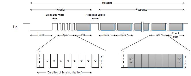
See the Architecture (TRM) for details of the LIN message frame format.
Baud Rate Setting
The baud rate, derived from the PERI clock, can be configured for each channel individually. PERI clock is input to the LIN block via the peripheral clock divider. The baud rate is configured by the peripheral clock divider value. Furthermore, there is a fixed signal oversampling factor of 16 in the LIN channel. Therefore, the baud rate is calculated as shown in Equation 1.
Equation 1
Equation 2 shows an example for the calculation of the divider setting value when PERI clock is 24 MHz and the required LIN baud rate is 20 kbps (20 kHz).
Equation 2
See Clocking System in the Architecture TRM for details of the PERI clock, peripheral clock divider, and divider value settings.
LIN Communication Example
This section describes how to implementation of the LIN communication using the Sample Driver Library (SDL). The code snippets in this application note are part of SDL. See Other References for the SDL.
SDL has a configuration part and a driver part. The configuration part configures the parameter values for the desired operation. The driver part configures each register based on the parameter values in the configuration part. You can configure the configuration part according to your system.
As the LIN is a deterministic in principle, the LIN Master has the scheduler that is activated periodically by the reference timer and controls the bus activity. Every frame is transmitted according to the predefined slots. Each LIN frame starts with the master header.
Furthermore, LIN Master has a schedule table, which is divided into time slots. The schedule is finished, when all time slots response frames are passed. A repetition of the table is executed by retriggering the scheduler, but the master node also has the flexibility to replace the schedule table by another one.
In the schedule table, the communication type of each time slot such as frame ID, message type, data length, and type of check sum used for the response is predetermined. The message type defines the response transmitter. If there are multiple slaves, then the message type defines the slave which will transmit a response. In LIN communication, two checksum types are supported: classic mode and enhanced mode. In classic mode, the PID field is not included in the checksum calculation, only the data fields are included in the calculation; whereas in enhanced mode, the PID field is included along with the data fields in the checksum calculation. The checksum type is can be selected using the CHECKSUM_ENHANCED bit in the LIN_CH_CTL register. See the Registers TRM for details of checksum type.
Table 1 shows an example of a scheduled table.
Table 1. Example of a Scheduled Table
Time Slot | ID | Message Type | Data Length | Checksum Type |
|---|---|---|---|---|
1 | 0x01 | Slave Response | 8 | Enhanced |
2 | 0x02 | Master Response | 8 | Enhanced |
3 | 0x10 | Slave Response | 1 | Enhanced |
4 | 0x11 | Master Response | 1 | Enhanced |
5 | 0x20 | Slave-to-Slave | - | Enhanced |
In this example, the schedule table consists of five time slots 1 to 5.
The message type of time slot 1 is a slave response and data length are 8. Therefore, when the header is transmitted by scheduler trigger, the LIN slave transmits response data of 8 bytes to the master.
In time slot 4, there is a master response with one byte data length. The master node transmits 1 byte of data along with the header to the slave nodes.
Time slot 5 defines a slave-to-slave response. In this case, the response is only between dedicated slave nodes and the master can ignore the response.
Figure 3 shows LIN communication example between the master node and slave node as per the schedule listed in Table 1.
Figure 3. Communication Between LIN Master and Slave 1
- The master transmits a header with ID = 0x01 after the scheduler activation.
- After receiving the header, the slave transmits the response of 8 bytes to the master according to schedule table (time slot 1).
- When the master receives the response, the frame in time slot 1 is completed and the master waits for the next scheduler activation.
- When scheduler is activated, the master transmits the header with ID = 0x02.
- The master transmits a response of 8 bytes to the slave after transmitting header (time slot 2) and the master waits for the next scheduler activation.
- This operation procedure is repeated until the last time slot 5.
- After the operation of time slot 5 is completed, the next time the scheduler is activated starting with time slot 1.
LIN Message Transfer
In the SDL, to support different message types such as transmission and reception of header/response, the handling of the LIN master or LIN slave operation mode is implicitly done by following commands:
LIN_CMD_TX_HEADER: This command is used by the master to transmit the header.LIN_CMD_TX_RESPONSE: This command is used by the master or a slave to transmit a response.LIN_CMD_RX_RESPONSE: This command is used by the master or a slave to receive a response.
These commands are configured corresponding to the message type in Table 1. For details, see section 4 and section 5.
Event Generation
The LIN block generates interrupt events such as transmission completion,
reception completion, and error detection. Each LIN channel has its dedicated
interrupt signal and its own interrupt registers: LIN_CH_INTR, LIN_CH_INTR_SET, LIN_CH_INTR_MASK, and LIN_CH_INTR_MASKED. In this
implementation example, INTR_MASK controls interrupt generation, and the
LIN_CH_CMD.INTR_MASKD register checks the interrupt source.
Table 2 lists send/receive events detected by the master and slave nodes in the SDL.
Table 2. List of Send/Receive Events
Send/Receive Events | Master | Slave |
|---|---|---|
| ✓ | - |
| - | ✓ |
| ✓ | ✓ |
| ✓ | ✓ |
| ✓ | ✓ |
| ✓ | ✓ |
| - | ✓ |
Table 3 lists the error events detected by the master and slave nodes.
Table 3. List of Error Events
Error Events | Master | Slave |
|---|---|---|
| ✓ | ✓ |
| ✓ | ✓ |
| ✓ | ✓ |
| - | ✓ |
| ✓ | ✓ |
| ✓ | ✓ |
| ✓ | - |
The related interrupt registers have a bit corresponding to these events. The software can control the generation of events by setting or clearing the corresponding bits.
See the Architecture TRM and Registers TRM for details of events and each interrupt register.
Example of Master Operation
This section shows an example implementation of a LIN Master using Table 1. In the SDL, you can manage the state machine using commands. Figure 4 shows the operation of LIN Master state machine.
Figure 4. LIN Master State Machine
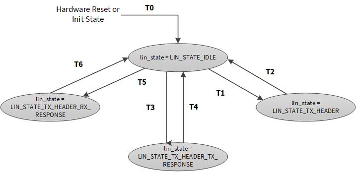
LIN Master state machine has the following four states.
LIN_STATE_IDLE: This is the default state after initialization. This state is entered when the LIN Master IRQ handler is completed.LIN_STATE_TX_HEADER_RX_RESPONSE: This is the state when the message type is a slave response. The master sends a header and waits for a response from the slave.LIN_STATE_TX_HEADER_TX_RESPONSE: This is the state when the message type is a master response. The master sends a header and a response to the slave.LIN_STATE_TX_HEADER: This is the state when the message type is slave-to-slave. The master sends only a header.
The software determines the state according to the message type of the schedule table, and sets the command sequence according to the current state.
Table 4 shows the relationship between message type, states and command sequence.
Table 4. Correspondence of message type, State, and Command Sequence settings in LIN Master Node
Message Type | State | Command | |||
|---|---|---|---|---|---|
TX_HEADER | RX_HEADER | TX_RESPONSE | RX_RESPONSE | ||
Slave Response |
| 1 | 0 | 0 | 1 |
Master Response |
| 1 | 0 | 1 | 0 |
Slave-to-Slave |
| 1 | 0 | 0 | 0 |
The following is an example of initialization and interrupt control to execute these processes.
LIN Master Initialization
Figure 5 shows the flow example for LIN Master Initialization.
Figure 5. LIN Master Initialize Flow Example

- Initialize LIN Master.
- Enable LIN Channel.
Software enables the external LIN transceiver after port setting is completed.
This example does not control the external LIN transceiver because
LIN_CH_CTL0.AUTO_EN is set to “0” in step 4 of this setup procedure. In this
case, the software can control the EN-pin via the register bit
TX_RX_STATUS.EN_OUT. If the LIN_EN_OUT pin for this deployed channel is
not available on the MCU, EN-pin on the transceiver can be also controlled by
a normal GPIO output.
- Initialize software state machine.
Set current state to lin_state = LIN_STATE_IDLE.
- Start the timer for starting the scheduler.
The communication starts automatically when the scheduler starts by this setting.
For details for clock setting, port setting, and Interrupt Controller setting, see the Architecture TRM and Registers TRM.
Use Case
This section describes a use case of LIN Master Initialization with the following parameters.
- Master/Slave Node : Master Node
- LIN Instance : LIN0_CH0
- Baud Rate : 19231 Hz
Configuration and Example
Table 5 lists the parameters of the configuration part in SDL for LIN Master Initialization.
Table 5. List of LIN Master Initialization Parameters
Parameters | Description | Setting Value |
|---|---|---|
For CLK | ||
CY_LINCH0_PCLK | Peripheral Clock Number | PCLK_LIN0_CLOCK_CH_EN0 |
For LIN | ||
config.bMasterMode | Master or Slave Mode | true (Master Mode) |
config.bLinTransceiverAutoEnable | LIN transceiver auto enable: | true (Enable) |
config.u8BreakFieldLength | Break/wakeup length (minus 1) in bit periods: | 13ul (13-1 = 12 bit) |
config.enBreakDelimiterLength | Break delimiter length: | LinBreakDelimiterLength1bits (1 bit) |
config.enStopBit | STOP bit periods | LinOneStopBit (1 bit) |
config.bFilterEnable | RX filter | true |
CY_LINCH0_TYPE | Define using LIN Channel Number | Assigned to LIN0 channel 0 |
Code Listing 1 demonstrates an example program to initialize the LIN Master in the configuration part.
Code Listing 1 CYT2 Series: Example to initialize LIN in Configuration Part (Master)
    int main(void)
    {
        :
        /* LIN baudrate setting */
        {
            /* Note:
             * LIN IP does oversampling and oversampling count is fixed 16.
             * Therefore LIN baudrate = LIN input clock / 16.
             */
             Cy_SysClk_PeriphAssignDivider(CY_LINCH0_PCLK, CY_SYSCLK_DIV_16_BIT, 0ul); /*Configure the Baud Rate Clock*1*/
             /*Configure the Baud Rate Clock*1*/
             Cy_SysClk_PeriphSetDivider(CY_SYSCLK_DIV_16_BIT, 0ul, 259ul); // 80 MHz / 260 /
    16 (oversampling) = 19231 Hz
    Cy_SysClk_PeriphEnableDivider(CY_SYSCLK_DIV_16_BIT, 0ul);   /*Configure the Baud Rate Clock*1*/
        }

        :
        /* Initialize LIN */
        {
        stc_lin_config_t config =    /*Configure LIN Master parameters*/
            {
                .bMasterMode = true,
                .bLinTransceiverAutoEnable = true,
                .u8BreakFieldLength = 13ul,
                .enBreakDelimiterLength = LinBreakDelimiterLength1bits,
                .enStopBit = LinOneStopBit,
                .bFilterEnable = true
            };

    /* (1)Initialize LIN Master based on above structure (See Code Listing 3) */
            /* (2)Enable LIN_CH0 (See Code Listing 3)  */
            Lin_Init(CY_LINCH0_TYPE, &config);

    lin_state = LIN_STATE_IDLE;      /*(3)Initialize the state machine*/
        }

        /* Start scheduling */
        SchedulerInit();             /*(4)Start the Timer (See Code Listing 2)*/
    }
*1: For details, refer to the “Clocking System” section in the Architecture TRM.
Code Listing 2 demonstrates an example of SchedulerInit.
Code Listing 2 Example of SchedulerInit
    static void SchedulerInit(void)
    {
        Cy_SysTick_Init(CY_SYSTICK_CLOCK_SOURCE_CLK_CPU, SYSTICK_RELOAD_VAL);
        Cy_SysTick_SetCallback(0ul, LIN0_TickHandler);
        Cy_SysTick_Enable();                           /*(4)Start the timer*/
    }
Code Listing 3 demonstrates an example program to configure LIN in the driver part.
The following description will help you understand the register notation of the driver part of SDL:
- pstcLin->unCTL0 is the LINx_CHy_CTL0 register mentioned in the Registers TRM. Other registers are also described in the same manner. 'x' signifies LIN instance number, 'y' is the channel number.
- Performance improvement measures:
To improve the performance of setting a register, the SDL writes a complete 32-bit data to the register. Each bit field is generated in advance in a bit- writable buffer and written to the register as the final 32-bit data.
ctl0.stcField.u1BIT_ERROR_IGNORE = 0ul; ctl0.stcField.u1PARITY = 0ul; ctl0.stcField.u1PARITY_EN = 0ul; pstcLin->unCTL0.u32Register = ctl0.u32Register;
- See cyip_lin.h under hdr/rev_x/ip for more information on the union and structure representation of registers.
Code Listing 3 Lin_Init
    /*******************************************************************************
    * Function Name: Lin_Init
    *******************************************************************************/
    cy_en_lin_status_t Lin_Init( volatile stc_LIN_CH_t* pstcLin, const stc_lin_config_t *pstcConfig)
    {
        cy_en_lin_status_t status = CY_LIN_SUCCESS;

        /* Check if pointers are valid */
        if ( ( NULL == pstcLin )          ||    /*Check if parameter values are valid.*/
             ( NULL == pstcConfig ) )
        {
            status = CY_LIN_BAD_PARAM;
        }
        else if (pstcConfig->bMasterMode &&
        ((LIN_MASTER_BREAK_FILED_LENGTH_MIN > pstcConfig->u8BreakFieldLength) ||
                  (LIN_BREAK_WAKEUP_LENGTH_BITS_MAX < pstcConfig->u8BreakFieldLength)))
        {
            status = CY_LIN_BAD_PARAM;
        }
        else if (LIN_BREAK_WAKEUP_LENGTH_BITS_MAX < pstcConfig->u8BreakFieldLength)
        {
            status = CY_LIN_BAD_PARAM;
        }
        else
        {
            un_LIN_CH_CTL0_t ctl0 = { 0ul };

            /* Stop bit length */
            ctl0.stcField.u2STOP_BITS = pstcConfig->enStopBit; /*(1)Initialize the LIN with parameter*/
            /* LIN Transceiver Auto Enable by Hardware */
            ctl0.stcField.u1AUTO_EN = pstcConfig->bLinTransceiverAutoEnable; /*(1)Initialize the LIN with parameter*/
            /* Break field length */
            ctl0.stcField.u5BREAK_WAKEUP_LENGTH = pstcConfig->u8BreakFieldLength - 1ul; /*(1)Initialize the LIN with parameter*/
            /* Break Delimiter Length: Bit8-9 */
            /* This field effect only master node header transmission. */
            ctl0.stcField.u2BREAK_DELIMITER_LENGTH = pstcConfig->enBreakDelimiterLength; /*(1)Initialize the LIN with parameter*/
            /* Mode of Operation: Bit 24: 0 -> LIN Mode, 1 -> UART Mode */ /*(1)Initialize the LIN with parameter*/
            ctl0.stcField.u1MODE = 0ul;    /*(1)Initialize the LIN with parameter*/
            /* Enable the LIN Channel */
            ctl0.stcField.u1ENABLED = 1ul; /*(2)Enable LIN_CH0*/
            /* Filter setting */
            ctl0.stcField.u1FILTER_EN = pstcConfig->bFilterEnable;    /*(1)Initialize the LIN with parameter*/
            /* Other settings are set to default */
            ctl0.stcField.u1BIT_ERROR_IGNORE = 0ul /*(1)Initialize the LIN with parameter*/
            ctl0.stcField.u1PARITY = 0ul;    /*(1)Initialize the LIN with parameter*/
            ctl0.stcField.u1PARITY_EN = 0ul;    /*(1)Initialize the LIN with parameter*/
            pstcLin->unCTL0.u32Register = ctl0.u32Register;   /*(1)Initialize the LIN with parameter*/

        }
        return status;
    }
Example of LIN Communication of LIN Master
When the LIN communication starts, the interrupt activates the master scheduler handler. Figure 6 shows example of how the master schedule handler works.
Figure 6. Example of Master Schedule Handler
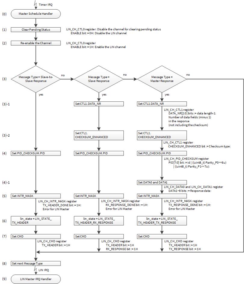
The following is the application software operation for the scheduler:
(0) The timer IRQ activates the master schedule handler on the LIN Master.
(1) Initializes the current pending state by configuring LIN_CH_CTL0.ENABLE
to “0”.All non-retained MMIO registers (for example, the LIN_CH_STAUS,
LIN_CH_CMD, and LIN_CH_INTR registers) are reset to default values by
setting LIN_CH_CTL0.ENABLE to “0”. See the Registers TRM for details of the
registers to be initialized.
(2) Re-enables the LIN channel.
(3) Checks the message type of the next frame. This is the message type specified in the current scheduler. If the message type is slave response or master response, it will configure the data length of the response field ((3)-1) and the checksum type ((3)-2) accordingly.
(4) Write the PID field of the header. LIN_CH_PID_CHECKSUM.PID[7] is parity
[1], LIN_CH_PID_CHECKSUM.PID[6] is parity [0], and
LIN_CH_PID_CHECKSUM.PID[5:0] is ID. Software needs to calculate the PID
field parity bits P[1] and P[0]. Parity is calculated as follows:
P[0] = (ID[4] ^ ID[2] ^ ID[1] ^ ID[0])
P[1] = ! (ID[5] ^ ID[4] ^ ID[3] ^ ID[1])
- In case of Master Response: The LIN master writes the response data of the required data length into the data register (DATA
0/1). (4)-1
(5) The LIN_CH_INTR_MASK register enables the event interrupt according to
the cases:
- Slave-to-Slave Response:
Configure the TX_HEADER_DONE to “1”
Configure the error detection bit to “1”.
- Slave Response:
Configure the RX_RESPONSE_DONE to “1”
Configure the RX_RESPONSE_DONE to “1”
v
- Master Response:
Configure the TX_RESPONSE_DONE to “1”
Configure the error detection bit to “1”.
It is necessary to set the required error detection bit depending on the system.
(6) Set the state according to the current message type:
- Slave-to-slave Response:
Configure the lin_state to LIN_STATE_TX_HEADER
- Slave Response:
Configure the lin_state to LIN_STATE_TX_HEADER_RX_RESPONSE
- Master Response:
Configure the lin_state to LIN_STATE_TX_HEADER_TX_RESPONSE
(7) Set the command sequence according to the lin_state for each case:
- Slave-to-slave Response:
Configure the LIN_CH_CMD.TX_HEADER to “1”
- Slave Response:
Configure the LIN_CH_CMD.TX_HEADER to “1”
Configure the LIN_CH_CMD.RX_RESPONSE to “1”
- Master Response:
Configure the LIN_CH_CMD.TX_HEADER to “1”
Configure the LIN_CH_CMD.TX_RESPONSE to “1” (a response is transmitted after
the transmission of the header)
(8) Set the message type for the next scheduler activation according to Table 1.
(9) Returns from the scheduler (timer interrupt) and waits for the occurrence of the configured LIN interrupt as shown in Table 2
Use Case
This section describes an example of determining the message type and performing LIN Master Communication.
- Master/Slave Node : Master Node
- LIN Instance : LIN0_CH0
- Communication Operation : See Table 1 and- Section 4.
Configuration and Example
Table 6 lists the parameters of the configuration part in SDL for LIN Communication (LIN Master)
Table 6. List of LIN Communication Parameters
Parameters | Description | Setting Value |
|---|---|---|
For LIN | ||
msgContext[] | ID/ Message Type | 0x01ul / LIN_RX_RESPONSE 0x02ul / LIN_TX_RESPONSE 0x10ul / LIN_RX_RESPONSE 0x11ul / LIN_TX_RESPONSE 0x20ul / LIN_TX_HEADER |
Checksum Type | LinChecksumTypeExtended | |
Data Length | 8ul or 1ul | |
CY_LINCH0_TYPE | Define using LIN Channel Number | Assigned to LIN0 channel 0 |
Code Listing 4 demonstrates an example program to communicate LIN in the configuration part.
Code Listing 4 CYT2 Series: Example to communicate LIN in Configuration Part (Master)
    lin_message_context msgContext[] =
    {
    {0x01ul, LIN_RX_RESPONSE, LinChecksumTypeExtended, 8ul,},     /*Set msgContext Table  1 */
        {0x02ul, LIN_TX_RESPONSE, LinChecksumTypeExtended, 8ul,},     /*Set msgContext Table  1 */
        {0x10ul, LIN_RX_RESPONSE, LinChecksumTypeExtended, 1ul,},     /*Set msgContext Table  1 */
        {0x11ul, LIN_TX_RESPONSE, LinChecksumTypeExtended, 1ul,},     /*Set msgContext Table  1 */
        {0x20ul, LIN_TX_HEADER, LinChecksumTypeExtended, 8ul,},     /*Set msgContext Table  1 */
    };
        :
    int main(void)
    {
        :

    /* Master schedule handler */
    static void LIN0_TickHandler(void)
    {
        /* Disable the channel for clearing pending status */
        Lin_Disable(CY_LINCH0_TYPE);     /* 1)Initializes the current pending state for LIN0_CH0 Code Listing 5 */

        /* Re-enable the channel */
        Lin_Enable(CY_LINCH0_TYPE);     /* (2)Re-enables the LIN channel Code Listing 6 */

        switch(msgContext[scheduleIdx].responseDirection) /* (3)Checks the message type */
        {
        case LIN_TX_RESPONSE:
            /* Response Direction = Master to Slave */
            /* (3)-1 Configure the data length of the response field Code Listing 7 */
            /* (3)-2 Configure the checksum type Code Listing 8 */
            Lin_SetDataLength(CY_LINCH0_TYPE, msgContext[scheduleIdx].dataLength);

            Lin_SetChecksumType(CY_LINCH0_TYPE, msgContext[scheduleIdx].checksumType);


            /* (4)Configure the PID field Code Listing 9 */
            Lin_SetHeader(CY_LINCH0_TYPE, msgContext[scheduleIdx].id);

            /* (4)-1 Configure the data register Code Listing 10 */
            Lin_WriteData(CY_LINCH0_TYPE, msgContext[scheduleIdx].dataBuffer, msgContext[scheduleIdx].dataLength);


            /* (5)Enables the event interrupt Code Listing 11 */
            Lin_SetInterruptMask(CY_LINCH0_TYPE, LIN_INTR_TX_RESPONSE_DONE | LIN_INTR_ALL_ERROR_MASK_MASTER);


            /* (6)Configure the lin_state */
            lin_state = LIN_STATE_TX_HEADER_TX_RESPONSE;

            /* (7)Configure the command sequence Code Listing 12 */
            Lin_SetCmd(CY_LINCH0_TYPE, LIN_CMD_TX_HEADER_TX_RESPONSE);
            break;

        case LIN_RX_RESPONSE:
            /* Response Direction = Slave to Master */
            /* (3)-1 Configure the data length of the response field Code Listing 7 */
            Lin_SetDataLength(CY_LINCH0_TYPE, msgContext[scheduleIdx].dataLength);

    /* (3)-2 Configure the checksum type Code Listing 8 */
            Lin_SetChecksumType(CY_LINCH0_TYPE, msgContext[scheduleIdx].checksumType);

    /* (4)Configure the PID field Code Listing 9 */
            Lin_SetHeader(CY_LINCH0_TYPE, msgContext[scheduleIdx].id);

    /* (5)Enables the event interrupt Code Listing 11 */
            Lin_SetInterruptMask(CY_LINCH0_TYPE, LIN_INTR_RX_RESPONSE_DONE | LIN_INTR_ALL_ERROR_MASK_MASTER);

            /* (6)Configure the lin_state */
            lin_state = LIN_STATE_TX_HEADER_RX_RESPONSE;

    /* (7)Configure the command sequence Code Listing 12 */
            Lin_SetCmd(CY_LINCH0_TYPE, LIN_CMD_TX_HEADER_RX_RESPONSE);
            break;

        case LIN_TX_HEADER:
            /* Response Direction = Slave to Slave */
            /* (4)Configure the PID field Code Listing 9 */
            Lin_SetHeader(CY_LINCH0_TYPE, msgContext[scheduleIdx].id);
            /* (5)Enables the event interrupt Code Listing 11 */
            Lin_SetInterruptMask(CY_LINCH0_TYPE, LIN_INTR_TX_HEADER_DONE | LIN_INTR_ALL_ERROR_MASK_MASTER);


            /* (6)Configure the lin_state */
            lin_state = LIN_STATE_TX_HEADER;
            /* (7)Configure the command sequence Code Listing 12 */
            Lin_SetCmd(CY_LINCH0_TYPE, LIN_CMD_TX_HEADER);
            break;
        default:
            break;
        }

        /* (8)Configure the message type for the next scheduler activation */
        scheduleIdx = (scheduleIdx + 1ul) % (sizeof(msgContext) / sizeof(msgContext[0ul]));
    }
Code Listing 5 to Code Listing 12 demonstrates an example to communicate LIN in the driver part.
Code Listing 5 Lin_Disable
    /******************************************************************************
     ** \brief Disable LIN channel.
    ******************************************************************************/
    cy_en_lin_status_t Lin_Disable(volatile stc_LIN_CH_t* pstcLin)
    {
        cy_en_lin_status_t ret = CY_LIN_SUCCESS;
        if (NULL == pstcLin)                     /* Check if parameter values are valid */
        {
            ret = CY_LIN_BAD_PARAM;
        }
        else
        {
            pstcLin->unCTL0.stcField.u1ENABLED = 0ul;    /* (1)Disable the LIN */
        }
        return ret;
    }
Code Listing 6 Lin_Enable
    /******************************************************************************
     ** \brief Enable LIN channel.
    ******************************************************************************/
    cy_en_lin_status_t Lin_Enable(volatile stc_LIN_CH_t* pstcLin)       /* Check if parameter values are valid */
    {
        cy_en_lin_status_t ret = CY_LIN_SUCCESS;
        if (NULL == pstcLin)
        {
            ret = CY_LIN_BAD_PARAM;
        }
        else
        {
            pstcLin->unCTL0.stcField.u1ENABLED = 1ul;        /* (2)Enable the LIN */
        }
        return ret;
    }
Code Listing 7 Lin_SetDataLength
    /******************************************************************************
     ** \brief Setup LIN response field data length
    ******************************************************************************/
    cy_en_lin_status_t Lin_SetDataLength(volatile stc_LIN_CH_t* pstcLin, uint8_t length)
    {
        cy_en_lin_status_t ret = CY_LIN_SUCCESS;
        if ((NULL == pstcLin) ||        /* Check if parameter values are valid */
            (length > LIN_DATA_LENGTH_MAX) ||
            (length < LIN_DATA_LENGTH_MIN))
        {
            ret = CY_LIN_BAD_PARAM;
        }
        else
        {
            /* (3)-1 Configure the data length of the response field */
            pstcLin->unCTL1.stcField.u3DATA_NR = length - 1ul;
        }
        return ret;
    }
Code Listing 8 Lin_SetChecksumType
    /******************************************************************************
     ** \brief Setup LIN checksum type setting
    ******************************************************************************/
    cy_en_lin_status_t Lin_SetChecksumType(volatile stc_LIN_CH_t* pstcLin, en_lin_checksum_type_t type)
    {
        cy_en_lin_status_t ret = CY_LIN_SUCCESS;
        if (NULL == pstcLin)              /* Check if parameter values are valid */
        {
            ret = CY_LIN_BAD_PARAM;
        }
        else
        {
            pstcLin->unCTL1.stcField.u1CHECKSUM_ENHANCED = type;  /* (3)-2 Configure the checksum type */
        }
        return ret;
    }
Code Listing 9 Lin_SetHeader
    /******************************************************************************
     ** \brief Setup LIN header for master tx header operation
    ******************************************************************************/
    cy_en_lin_status_t Lin_SetHeader(volatile stc_LIN_CH_t* pstcLin, uint8_t id)
    {
        cy_en_lin_status_t ret = CY_LIN_SUCCESS;
        uint8_t TempPID;
        uint8_t Parity_P1, Parity_P0;
        cy_en_lin_status_t ret = CY_LIN_SUCCESS;
        uint8_t TempPID;
        uint8_t Parity_P1, Parity_P0;       /* Check if parameter values are valid */
        if ((NULL == pstcLin) ||
            (LIN_ID_MAX < id))
        {
            ret = CY_LIN_BAD_PARAM;
        }
        else
        {
            /* Calculate the Parity bits P0 & P1 */
            Parity_P0 = ((id) ^ (id>>1ul) ^
                         (id>>2ul) ^ (id>>4ul)) & 0x01ul;
            Parity_P1 = (~((id>>1ul) ^ (id>>3ul) ^
                           (id>>4ul) ^ (id>>5ul))) & 0x01ul;
            /* Assign the Parity bits and the header values in to the TempPID */
            TempPID = id | ((uint8_t) Parity_P0<<6ul) | ((uint8_t) Parity_P1<<7ul);
            /* Write the TempID value in to the TX_HEADER register */
            /* (4)Configure the PID field */
            pstcLin->unPID_CHECKSUM.stcField.u8PID = TempPID;
        }
        return ret;
    }
Code Listing 10 Lin_WriteData
    /******************************************************************************
     ** \brief Write response data.
    ******************************************************************************/
    cy_en_lin_status_t Lin_WriteData( volatile stc_LIN_CH_t* pstcLin, const uint8_t *au8Data, uint8_t u8DataLength )
    {
        cy_en_lin_status_t status = CY_LIN_SUCCESS;
        un_LIN_CH_DATA0_t data0 = { 0ul };
        un_LIN_CH_DATA1_t data1 = { 0ul };
        uint8_t u8Cnt;
        /* Check if NULL pointer */       /* Check if parameter values are valid */
        if( ( NULL == pstcLin ) ||
            ( NULL == au8Data ) )
        {
            status = CY_LIN_BAD_PARAM;
        }
        /* Check if data length is valid */       /* Check if parameter values are valid */
        else if( LIN_DATA_LENGTH_MAX < u8DataLength )
        {
            status = CY_LIN_BAD_PARAM;
        }
        /* Check if the bus is free */       /* Check if parameter values are valid */
        else if( 0ul == pstcLin->unSTATUS.stcField.u1TX_BUSY )
        {

            /* Write data in to the temp variables */
            for( u8Cnt = 0ul; u8Cnt < u8DataLength; u8Cnt++ )
            {
                if( 4ul > u8Cnt )
                {
                    data0.au8Byte[u8Cnt] = au8Data[u8Cnt];
                }
                else
                {
                    data1.au8Byte[u8Cnt - 4ul] = au8Data[u8Cnt];
                }
            }
            /* Write data to HW FIFO */
            /* (4)-1 Configure the data register (DATA 0) */
            pstcLin->unDATA0.u32Register = data0.u32Register;
            /* (4)-1 Configure the data register (DATA 1) */
            pstcLin->unDATA1.u32Register = data1.u32Register;
        }
        else
        {
            status = CY_LIN_BUSY;
            /* A requested operation could not be completed */
        }
        return status;
    }
Code Listing 11 Lin_SetInterruptMask
    /******************************************************************************
     ** \brief Setup interrupt source to be accepted.
    ******************************************************************************/
    cy_en_lin_status_t Lin_SetInterruptMask(volatile stc_LIN_CH_t* pstcLin, uint32_t mask)
    {
        cy_en_lin_status_t ret = CY_LIN_SUCCESS;
        if (NULL == pstcLin)                              /* Check if parameter values are valid */
        {
            ret = CY_LIN_BAD_PARAM;
        }
        else
        {
        pstcLin->unINTR_MASK.u32Register = mask;           /* (5)Enables the event interrupt */
        }
        return ret;
    }
Code Listing 12 Lin_SetCmd
    /******************************************************************************
     ** \brief Setup LIN operation command
    ******************************************************************************/
    cy_en_lin_status_t Lin_SetCmd(volatile stc_LIN_CH_t* pstcLin, uint32_t command)
    {
        cy_en_lin_status_t ret = CY_LIN_SUCCESS;
        un_LIN_CH_CMD_t cmdReg = pstcLin->unCMD;
        if (NULL == pstcLin)                           /* Check if parameter values are valid */
        {
            ret = CY_LIN_BAD_PARAM;
        }
        else if (((command & (LIN_CH_CMD_TX_HEADER_Msk | LIN_CH_CMD_RX_HEADER_Msk))
                    == (LIN_CH_CMD_TX_HEADER_Msk | LIN_CH_CMD_RX_HEADER_Msk))   ||
                (((command & LIN_CH_CMD_TX_WAKEUP_Msk) != 0ul) &&
                 ((command & (LIN_CH_CMD_TX_HEADER_Msk |
                              LIN_CH_CMD_TX_RESPONSE_Msk |
                              LIN_CH_CMD_RX_HEADER_Msk |
                              LIN_CH_CMD_RX_RESPONSE_Msk)) != 0ul)))
        {
            ret = CY_LIN_BAD_PARAM;
        }
        else if (((cmdReg.stcField.u1TX_HEADER != 0ul) && (command & LIN_CH_CMD_RX_HEADER_Msk) != 0ul) ||
                 ((cmdReg.stcField.u1RX_HEADER != 0ul) && (command & LIN_CH_CMD_TX_HEADER_Msk) != 0ul) ||
                 ((cmdReg.stcField.u1TX_WAKEUP != 0ul) &&
                                ((command & (LIN_CH_CMD_TX_HEADER_Msk |
                                             LIN_CH_CMD_TX_RESPONSE_Msk |
                                             LIN_CH_CMD_RX_HEADER_Msk |
                                             LIN_CH_CMD_RX_RESPONSE_Msk)) != 0ul)))
        {
            ret = CY_LIN_BUSY;
        }
        else
        {
        pstcLin->unCMD.u32Register = command;         /* (7)Configure the command sequence */
        }
        return ret;
    }
Example of LIN Master Interrupt Handling
When an interrupt set by the scheduler occurs, LIN Master IRQ handler is activated. Figure 7 shows example to how the LIN Master IRQ handler works.
Figure 7. Example of LIN Master IRQ Handler
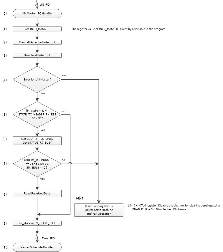
The following is the application software operation for the LIN master IRQ handler:
(0) LIN IRQ activates the LIN Master IRQ handler.
(1) Acquire interrupt information from LIN_CH_MASKED register.
(2) Clear all accepted interrupt.
(3) Disable all interrupt to prevent occurrence of different interrupt during interrupt handling.
(4) Check if an error occurred. If yes, go to (4)-1.
(4)-1 Clear the currently pending state by LIN_CH_CTL0.ENABLE being set to
“0”, and delete the state in the hardware internal state machine and the
software state machine. After that, execute error handling.
(5) When no communication error is detected, check the current state (lin_state) of the software state machine, which is decided by the scheduler handler (6) in Figure 6.
- If current state is not ,
- , go to (9)
(6) If current state is LIN_STATE_TX_HEDER_RX_RESPONSE, get the condition of
LIN_CH_CMD.RX_RESPONSE and LIN_CH_STATUS.RX_BUSY.
(7) Check the bit fields of LIN_CH_CMD.RX_RESPONSE and
LIN_CH_STATUS.RX_BUSY.
- The hardware sets
LIN_CH_CMD.RX_RESPONSEto "0" on successful completion of the legal command sequences (not set to "0" when an error is detected) andLIN_CH_STATUS.RX_BUSYto “0” on successful completion of previous commands or when an error is detected. Therefore, reception is completed successfully, when both the bits are set to "0". - If
LIN_CH_CMD.RX_RESPONSEorLIN_CH_STATUS.RX_BUSYis “1”, reception is not completed correctly. In this case, go to (4)-1.
(8) Read the received data from DATA0 and DATA1 registers.
(9) Set the state to LIN_STATE_IDLE.
(10) Leave LIN Master IRQ handler, and wait for the next scheduler activation.
Use Case
This section describes an example in which the LIN Master Handler determines the interrupt factor, clears the interrupt factor, and executes the processing for current state.
- System Interrupt source : LINCH0 (IDX: 69)
- Mapped to CPU Interrupt : IRQ3
- CPU Interrupt Priority : 3
- Communication Operation : See Table 1 and Section 4.
Configuration and Example
Table 7 lists the parameters of the configuration part in SDL for LIN Master Interrupt Handler.
Table 7. List of LIN Master Interrupt Handler Parameters
Parameters | Description | Setting Value |
|---|---|---|
For Interrupt | ||
irq_cfg.sysIntSrc | System interrupt index number | CY_LINCH0_IRQN |
irq_cfg.intIdx | CPU interrupt number | CPUIntIdx3_IRQn |
irq_cfg.isEnabled | CPU interrupt enable | true (0x1) |
For LIN | ||
CY_LINCH0_TYPE | Define using LIN Channel Number | Assigned to LIN0 channel 0 |
Code Listing 13 demonstrates an example program to interrupt LIN in the configuration part.
Code Listing 13 CYT2 Series: Example to interrupt LIN in Configuration Part (Master)
    int main(void)
    {

        :
        __enable_irq(); /* Enable global interrupts. */
        :
        /* Register LIN interrupt handler and enable interrupt */
        {
            cy_stc_sysint_irq_t irq_cfg;
            irq_cfg = (cy_stc_sysint_irq_t){
                .sysIntSrc  = CY_LINCH0_IRQN,
                .intIdx     = CPUIntIdx3_IRQn,
                .isEnabled  = true,
            };
            Cy_SysInt_InitIRQ(&irq_cfg);     /* Set the parameters to interrupt structure*1 */
            Cy_SysInt_SetSystemIrqVector(irq_cfg.sysIntSrc, LIN0_IntHandler);     /* Set the system interrupt handler*1 */
            NVIC_SetPriority(CPUIntIdx3_IRQn, 0ul);     /* Set priority*1*/
            NVIC_EnableIRQ(CPUIntIdx3_IRQn);      /* Interrupt Enable*1 */
        }
        :
    /* LIN0 IRQ Handler */
    static void LIN0_IntHandler(void)
    {
        uint32_t maskStatus;
        cy_en_lin_status_t apiResponse;
        /* (1)Acquire interrupt information Code Listing 14 */
        Lin_GetInterruptMaskedStatus(CY_LINCH0_TYPE, &maskStatus);
        /* (2)Clear all accepted interrupt Code Listing 15 */
        Lin_ClearInterrupt(CY_LINCH0_TYPE, maskStatus);  /* Clear all accepted interrupt */


    /* (3)Disable all interrupt to prevent occurrence of different interrupt during interrupt handling Code Listing 11 */
        Lin_SetInterruptMask(CY_LINCH0_TYPE, 0uL);       /* Disable all interrupt */


         /* (4)Check if an error occurred */
        if ((maskStatus & LIN_INTR_ALL_ERROR_MASK_MASTER) != 0ul)
        {
            /* Wait for next tick. */
            lin_state = LIN_STATE_IDLE;
            /* Disable the channel to reset LIN status */
            /* (4)-1 Clear the currently pending state  */
            Lin_Disable(CY_LINCH0_TYPE);       /* (4)-1 Clear the currently pending state Code Listing 5 */
            /* Re-enable the channel */
            Lin_Enable(CY_LINCH0_TYPE);
        }
        else
        {
            switch(lin_state)
            {
            /* (5)Current state is not LIN_STATE_TX_HEADER_RX_RESPONSE */
            case LIN_STATE_TX_HEADER:
                /* Tx header complete with no error */
                break;
                /* (5)Current state is not LIN_STATE_TX_HEADER_RX_RESPONSE */
            case LIN_STATE_TX_HEADER_TX_RESPONSE:
                /* Tx response complete with no error */
                break;
                /* (6)Current state is LIN_STATE_TX_HEDER_RX_RESPONSE */
            case LIN_STATE_TX_HEADER_RX_RESPONSE:

                /* (7)Check the bit fields. */
                /* Tx header and rx response complete with no error */
                while(1)
                {
                /* (8)Read the received dataCode Listing 16. */
                    apiResponse = Lin_ReadData(CY_LINCH0_TYPE, msgContext[scheduleIdx].dataBuffer);
                    if(apiResponse == CY_LIN_SUCCESS)
                    {
                        break;
                    }
                }
                /* For testing
                 * Set rx data to tx data. Rx ID + 1 => Tx ID
                 */
                memcpy(msgContext[scheduleIdx + 1ul].dataBuffer, msgContext[scheduleIdx].dataBuffer, LIN_DATA_LENGTH_MAX);
                break;
            default:
                break;
            }
            lin_state = LIN_STATE_IDLE;        /* (9) Set the state to LIN_STATE_IDLE. */
        }
    }
*1 For details, refer to the CPU interrupt handing sections in the Architecture TRM
Code Listing 14 to Code Listing 16 demonstrates an example program to interrupt LIN in the driver part.
Code Listing 14 Lin_GetInterruptMaskedStatus
    /******************************************************************************
     ** \brief Return interrupt masked status.
    ******************************************************************************/
    cy_en_lin_status_t Lin_GetInterruptMaskedStatus(volatile stc_LIN_CH_t* pstcLin, uint32_t *status)
    {
        cy_en_lin_status_t ret = CY_LIN_SUCCESS;
        if ((NULL == pstcLin) ||        /* Check if parameter values are valid */
            (NULL == status))
        {
            ret = CY_LIN_BAD_PARAM;
        }
        else
        {
            *status = pstcLin->unINTR_MASKED.u32Register;     /* (1)Acquire interrupt information */
        }
        return ret;
    }
Code Listing 15 Lin_ClearInterrupt
    /******************************************************************************
     ** \brief Clear interrupt status.
    ******************************************************************************/
    cy_en_lin_status_t Lin_ClearInterrupt(volatile stc_LIN_CH_t* pstcLin, uint32_t mask)
    {
        cy_en_lin_status_t ret = CY_LIN_SUCCESS;
        if (NULL == pstcLin)        /* Check if parameter values are valid */
        {
            ret = CY_LIN_BAD_PARAM;
        }
        else
        {
            pstcLin->unINTR.u32Register = mask;    /* (2)Clear interrupt status */
        }
        return ret;
    }
Code Listing 16 Lin_ReadData
    /******************************************************************************
     ** \brief Read response data.
    ******************************************************************************/
    cy_en_lin_status_t Lin_ReadData( volatile stc_LIN_CH_t* pstcLin, uint8_t  *u8Data )
    {
        cy_en_lin_status_t status = CY_LIN_SUCCESS;
        uint8_t u8Cnt;
        uint8_t u8Length;
        /* Check if pointers are valid */
        if( ( NULL == pstcLin )           ||        /* Check if parameter values are valid */
            ( NULL == u8Data ))
        {
            status = CY_LIN_BAD_PARAM;
        }
        /* Check if the response is received successfully */
        else if( ( 0ul == pstcLin->unCMD.stcField.u1RX_RESPONSE ) &&
                 ( 0ul == pstcLin->unSTATUS.stcField.u1RX_BUSY ) )
        {
            u8Length = pstcLin->unCTL1.stcField.u3DATA_NR + 1ul;
            /* Copy the data in to u8Data array */
            un_LIN_CH_DATA0_t data0 = pstcLin->unDATA0;
            un_LIN_CH_DATA1_t data1 = pstcLin->unDATA1;        /* (8)Read response data */
            for ( u8Cnt = 0ul; u8Cnt < u8Length; u8Cnt++ )
            {
                if( 4ul > u8Cnt )
                {
                    u8Data[u8Cnt] = data0.au8Byte[u8Cnt];
                }
                else
                {
                    u8Data[u8Cnt] = data1.au8Byte[u8Cnt - 4ul];
                }
            }
        }
        else
        {
            status = CY_LIN_BUSY;
        }
        return status;
    }
Example of Slave Operation
This section shows an example implementation of the LIN Slave. The LIN Slave transmits or receives information depending on the schedule table from the LIN protocol analyzer that acts like a master. LIN Slave IRQ Handler includes a table; see Table 8 for an example of message frame ID processing and this information is used in Figure 11. The LIN Slave receives the header from the LIN master. Upon receiving the header, the response field corresponding to the received PID will be transmitted or received as shown in Table 8. To support these different message types, the handling of the LIN Slave operation is implicitly done by command sequences, as listed in the “LIN Slave Command Sequence” table in the Architecture TRM.
Table 8. Message Frame ID Processing Table of LIN Slave
ID | Message Type | Data Length | Checksum Type |
|---|---|---|---|
0x01 | Master Response | 8 | Enhanced |
0x02 | Slave Response | 8 | Enhanced |
0x10 | Master Response | 1 | Enhanced |
0x11 | Slave Response | 1 | Enhanced |
In this example, the software manages the configuration of command sequences using a state machine. Figure 8 shows the state machine for the LIN Slave. The arrows from T0 to T6 are the triggers for state transition.
Figure 8. LIN Slave State Machine
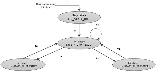
LIN slave state machine has following four states:
LIN_STATE_IDLE: This is the default state after initialization. The slave is neither receiving nor transmitting any information on the LIN bus.LIN_STATE_RX_HEADER: This is the state when the slave is ready for permanent LIN break detection. The slave is waiting for a successful header reception.LIN_STATE_RX_RESPONSE: This is the state when the message type is a master response. The slave waits for a response from the master.LIN_STATE_TX_RESPONSE: This is the state when the message type is a slave response. The slave sends a response to the master. If the message type is slave-to-slave, the slave sends a response to the other slave.
The software determines the state according to the message type of Table 8 and sets the command sequence according to the current state. Table 9 shows the relationship between message type, states, and command sequence.
Table 9. Correspondence between message type, State, and Command Sequence settings in LIN Slave
Message Type | State | TX_HEADER | RX_HEADER | TX_RESPONSE | RX_RESPONSE |
|---|---|---|---|---|---|
Slave Response |
| 0 | 1 | 1 | 1 |
Master Response |
| 0 | 1 | 0 | 1 |
The following is an example of initialization and interrupt control to execute these processes.
LIN Slave Initialization
Figure 9 shows the flow example for LIN Slave Initialization.
Figure 9. LIN Slave Initialize Flow Example

- Initialize LIN Slave.
- Enable LIN Channel.
Software enables the external LIN transceiver after port setting is completed.
This LIN example does not control the external LIN transceiver because
LIN_CH_CTL0.AUTO_EN is set to “0” in (1) of this setup procedure. In this
case, the software can control the EN-pin via the register bit
TX_RX_STATUS.EN_OUT. If the LIN_EN_OUT pin for this deployed channel is
not available on the MCU, the EN-pin on the transceiver can be also controlled
by a normal GPIO output.
- Initialize the software state machine.
Set the current state to lin_state = LIN_STATE_IDLE.
For details for Clock setting, port setting, and Interrupt Controller setting, see the Architecture TRM and Registers TRM.
Use Case
This section describes a use case of LIN Slave Initialization with the following parameters.
- Master/Slave Node : Slave Node
- LIN Instance : LIN0_CH0
- Baud Rate : 19231 Hz
Configuration and Example
Table 10 lists the parameters of the configuration part in SDL for LIN Master Initialization.
Table 10. List of LIN Slave Initialization Parameters
Parameters | Description | Setting Value |
|---|---|---|
For CLK | ||
CY_LINCH0_PCLK | Peripheral Clock Number | PCLK_LIN0_CLOCK_CH_EN0 |
For LIN | ||
lin_config.bMasterMode | Master or Slave Mode | false (Slave Mode) |
lin_config.bLinTransceiverAutoEnable | LIN transceiver auto enable: | true (Enable) |
lin_config.u8BreakFieldLength | Break/wakeup length (minus 1) in bit periods: | 11ul (11-1 = 10 bit) |
lin_config.enBreakDelimiterLength | Break delimiter length: | LinBreakDelimiterLength1bits (1 bit) |
lin_config.enStopBit | STOP bit periods | LinOneStopBit (1 bit) |
lin_config.bFilterEnable | RX filter | true |
CY_LINCH0_TYPE | Define using LIN Channel Number | Assigned to LIN0 channel 0 |
Code Listing 17 demonstrates an example program to initialize LIN Slave in the configuration part.
Code Listing 17 CYT2 Series: Example to initialize LIN in Configuration Part (Slave)
    /* Configure LIN Slave parameters */
    static const stc_lin_config_t lin_config =
    {
        .bMasterMode = false,
        .bLinTransceiverAutoEnable = true,
        .u8BreakFieldLength = 11ul,
        .enBreakDelimiterLength = LinBreakDelimiterLength1bits,
        .enStopBit = LinOneStopBit,
        .bFilterEnable = true
    };

        :
    int main(void)
    {
        :
        /* LIN baudrate setting */
        /* Note:
         * LIN IP does oversampling and oversampling count is fixed 16.
         * Therefore LIN baudrate = LIN input clock / 16.
         */
        /* Configure LIN Slave parameters */
        Cy_SysClk_PeriphAssignDivider(CY_LINCH0_PCLK, CY_SYSCLK_DIV_16_BIT, 0u);
        /* Configure LIN Slave parameters */
        Cy_SysClk_PeriphSetDivider(CY_SYSCLK_DIV_16_BIT, 0ul, 259ul); // 80 MHz / 260 / 16
    (oversampling) = 19231 Hz
        /* Configure LIN Slave parameters */
        /* Configure the Baud Rate Clock*1 */
        Cy_SysClk_PeriphEnableDivider(CY_SYSCLK_DIV_16_BIT, 0ul);

        /* Initialize LIN */
        /* (1)Initialize LIN Master based on above structure (See Code Listing 3) */
        /* (2)Enable LIN_CH0 (See Code Listing 3) */
        Lin_Init(CY_LINCH_TYPE, &lin_config);
        lin_state = LIN_STATE_IDLE;

        /* LIN operation */
        /* (3)Initialize the state machine */
        lin_state = LIN_STATE_RX_HEADER;
        :
    }
*1: For details, refer to the Clocking System sections in the Architecture TRM.
Example of LIN Slave Interrupt Handling
When an interrupt is set by header from master, LIN Slave IRQ handler is activated.
Figure 10 shows an example of how the LIN Slave IRQ handler works. This flow is used in Code Listing 18.
Figure 10. Example of LIN Slave IRQ Handler
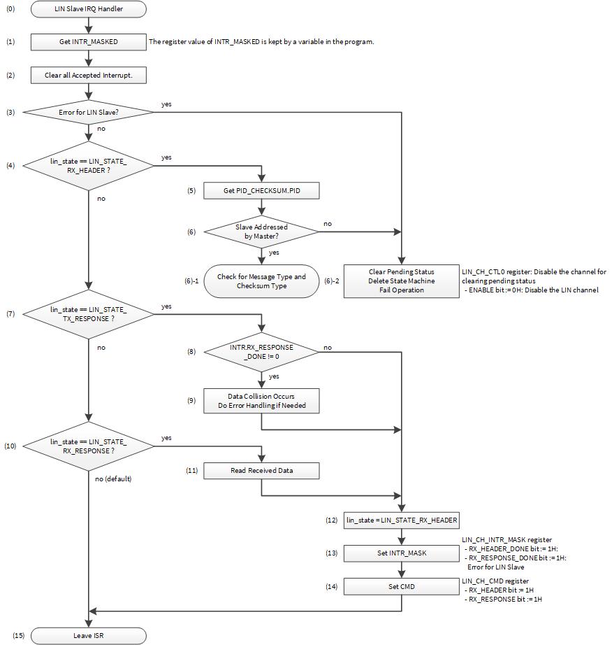
For the LIN Slave IRQ handler, the application software operation is as follows.
(0) The LIN slave IRQ handler is activated by LIN IRQ.
(1) Acquire interrupt information from LIN_CH_MASKED register.
(2) Clear all interrupt flags for initialized interrupt status.
(3) Check the occurrence of communication error. If an error is detected, then go to (6)-2.
(4) When there is no communication error, check the current state (lin_state) in the state machine.
- If current state is
LIN_STATE_RX_HEADER, go to (5). - If current state is not
LIN_STATE_RX_HEADER, go to (7).
(5) Get the received PID value from LIN_CH_PID_CHECKSUM.PID.
(6) Check the current ID. If the current ID is not in Table 8, go to (6)-2.
- If the ID is present in Table 8, go to (6)-1.
- (6)-1 Go to in Figure 11.
- (6)-2 Clear the currently pending state by setting
LIN_CH_CTL0.ENABLEto “0” and delete the state in the hardware internal state machine and the software state machine. After that, run to the appropriate fail operation depending on the system.
(7) Check the current state (lin_state) in state machine.
- If current state is LIN_STATE_TX_RESPONSE, go to (8). If not, go to (10).
(8) Check the condition of INTR.RX_RESPONSE_DONE.
Hardware configures LIN_CH_INTR.RX_RESPONSE_DONE to “1”, when a frame
response (data fields and checksum field) is received (the CMD.RX_RESPONSE
is completed).
If LIN_CH_INTR.RX_RESPONSE_DONE is “0”, there is no data collision. Go to
(12).
If LIN_CH_INTR.RX_RESPONSE_DONE is “1”, data collision occurs. Go to (9).
(9) Run the data collision operation depending on the system and go to (12).
(10) Check the current state (lin_state) in state machine.
- If current state is
LIN_STATE_RX_RESPONSE, go to (11). If not, go to (15).
(11) Read the reception data from DATA0 and DATA1.
(12) Configure the state to LIN_STATE_RX_HEADER.
(13) Enable event interrupt by LIN_CH_INTR_MASK register.
-
Configure
RX_HEADER_DONEto “1”. -
Configure
RX_RESPONSE_DONEto “1”. -
Configure the error detection bit to “1”.
-
It is necessary to Configure the required error detection bit depending on the system.
(14) Configure the Command Sequence
-
Configure
LIN_CH_CMD.RX_HEADERto “1”. -
Configure
LIN_CH_CMD.RX_RESPONSEto “1”.
(15) Return from LIN slave IRQ handler and wait for the occurrence of the configured LIN interrupt as Table 2.
Figure 11 shows how the message type and checksum type operations are performed. This flow is used in the case of jumping from (6) -1 in Figure 10 and in Code Listing 20.
Figure 11. Example of LIN Slave Checking for Message Type and Checksum Type
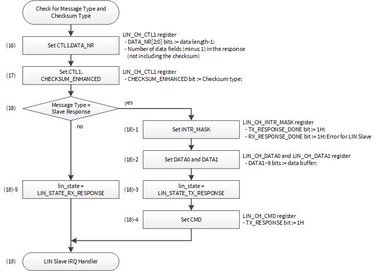
The following is the flow to check the message type and checksum type:
(16) Configure the data length of the response according to Table 8.
(17) Configure the checksum type according to Table 8.
(18) Check the current message type according to Table 8.
-
If the current message type is
LIN_TX_RESPONSE: -
(18)-1. Enable event interrupt by the LIN_CH_INTR_MASK register.
-
It is necessary to configure the required error detection bit depending on the system.
- Configure
RX_RESPONSE_DONEto “1” - Configure
TX_RESPONSE_DONEto “1” - Configure the error detection bit to “1”
- Configure
-
(18)-2. The LIN slave writes the response data of the required data length to the data register (DATA 0/1).
-
(18)-3. Configure lin_state to
LIN_STATE_TX_RESPONSE. -
(18)-4. Configure the Command Sequence according to the state. Configure
LIN_CH_CMD.TX_RESPONSEto “1”.- If the current message type is not LIN_TX_RESPONSE
-
(18)-5. Configure lin_state to
LIN_STATE_RX_RESPONSE.
(19) Return from LIN slave IRQ handler, and wait for the next interrupt event.
Use case
This section describes an example in which the LIN Slave Handler determines the interrupt factor, clears the interrupt factor, and executes the processing for current state.
- System Interrupt source : LINCH0 (IDX: 69)
- Mapped to CPU Interrupt : IRQ3
- CPU Interrupt Priority : 3
- Communication Operation : See Section 5 .
Configuration and Example
Table 11 lists the parameters of the configuration part in SDL for LIN Slave Interrupt Handler.
Table 11. List of LIN Slave Interrupt Handler Parameters
Parameters | Description | Setting Value |
|---|---|---|
For Interrupt | ||
lin_irq_cfg.sysIntSrc | System interrupt index number | CY_LINCH0_IRQN |
lin_irq_cfg.intIdx | CPU interrupt number | CPUIntIdx3_IRQn |
lin_irq_cfg.isEnabled | CPU interrupt enable | true (0x1) |
For LIN | ||
CY_LINCH0_TYPE | Define using LIN Channel Number | Assigned to LIN0 channel 0 |
Code Listing 18 demonstrates an example program to interrupt LIN in the configuration part.
Code Listing 18 CYT2 Series: Example to interrupt LIN in Configuration Part (Slave)
    #define CY_LINCH_IRQN           CY_LINCH0_IRQN
        :
    static const cy_stc_sysint_irq_t lin_irq_cfg =  /* Configure interrupt structure parameters*1 */
    {
        .sysIntSrc  = CY_LINCH_IRQN,
        .intIdx     = CPUIntIdx3_IRQn,
        .isEnabled  = true,
    };
        :
    int main(void)
    {
        :
        __enable_irq(); /* Enable global interrupts. */   /* Enable global interrupt*1 */
        :
        Cy_SysInt_InitIRQ(&lin_irq_cfg);   /* Set the parameters to interrupt structure*1 */
        Cy_SysInt_SetSystemIrqVector(lin_irq_cfg.sysIntSrc, LIN0_IntHandler);   /* Set the system interrupt handler*1 */
        NVIC_SetPriority(CPUIntIdx3_IRQn, 3ul);   /* Set priority*1 */
        NVIC_EnableIRQ(CPUIntIdx3_IRQn);    /* Interrupt Enable*1 */
        :

    /* LIN0 IRQ Handler */
    void LIN0_IntHandler(void)
    {
        uint32_t maskStatus;
        /* (1)Acquire interrupt information (See Code Listing 14) */
        Lin_GetInterruptMaskedStatus(CY_LINCH0_TYPE, &maskStatus);
        /* (2)Clear all interrupt flags (See Code Listing 15) */
        Lin_ClearInterrupt(CY_LINCH0_TYPE, maskStatus); /* Clear all accepted interrupt */
        cy_en_lin_status_t apiResponse;

        /* (3)Check if an error occurred */
        if ((maskStatus & CY_LIN_INTR_ALL_ERROR_MASK_SLAVE) != 0ul)
        {
            /* There are some error */
            /* Handle error if needed. */
            /* Disable the channel to reset LIN status */
            Lin_Disable(CY_LINCH0_TYPE);
            /* Re-enable the channel */
            Lin_Enable(CY_LINCH0_TYPE);
            /* Re enable header RX */
            lin_state = LIN_STATE_RX_HEADER;
            Lin_SetInterruptMask(CY_LINCH0_TYPE, CY_LIN_INTR_RX_HEADER_DONE | CY_LIN_INTR_RX_RESPONSE_DONE | CY_LIN_INTR_ALL_ERROR_MASK_SLAVE);
            Lin_SetCmd(CY_LINCH0_TYPE, CY_LIN_CMD_RX_HEADER_RX_RESPONSE);
        }
        else
        {
            bool acceptedId = false;
            uint8_t id, parity;
            switch(lin_state)
            {
            case LIN_STATE_RX_HEADER:    /* (4)Current state is LIN_STATE_RX_HEADER */
                /* Rx header complete with no error */
                Lin_GetHeader(CY_LINCH0_TYPE, &id, &parity);    /* (5)Get the received PID value (See Code Listing 19) */
                /* Analyze ID */    /* (6)Check the current ID */
                for (uint8_t I = 0ul; I < (sizeof(msgContext) / sizeof(msgContext[0ul])); i++)
                {
                    if (id == msgContext[i].id)
                    {
                        currentMsgIdx = I;
                        acceptedId = true;
                        break;
                    }
                }
                if (acceptedId)
                {
                    /* Setup checksum type and data length */
                    Lin_SetDataLength(CY_LINCH0_TYPE, msgContext[currentMsgIdx].dataLength);
                    Lin_SetChecksumType(CY_LINCH0_TYPE, msgContext[currentMsgIdx].checksumType);
                    if (msgContext[currentMsgIdx].responseDirection == LIN_TX_RESPONSE)
                    {
                        Lin_SetInterruptMask(CY_LINCH0_TYPE, CY_LIN_INTR_TX_RESPONSE_DONE | CY_LIN_INTR_RX_RESPONSE_DONE | CY_LIN_INTR_ALL_ERROR_MASK_SLAVE);
                        Lin_WriteData(CY_LINCH0_TYPE, msgContext[currentMsgIdx].dataBuffer, msgContext[currentMsgIdx].dataLength);
                        lin_state = LIN_STATE_TX_RESPONSE;
                        Lin_SetCmd(CY_LINCH0_TYPE, CY_LIN_CMD_TX_RESPONSE);
                    }
                    else
                    {
                        lin_state = LIN_STATE_RX_RESPONSE;
                    }
                }
                else
                {
                    /* Message to be ignored */
                    /* Disable the channel to reset LIN status */
                    Lin_Disable(CY_LINCH0_TYPE);      /* (6)-2 Clear the currently pending state (See Code Listing 5) */
                    /* Re-enable the channel */
                    Lin_Enable(CY_LINCH0_TYPE);
                    /* Re enable header RX */
                    lin_state = LIN_STATE_RX_HEADER;
                    Lin_SetInterruptMask(CY_LINCH0_TYPE, CY_LIN_INTR_RX_HEADER_DONE | CY_LIN_INTR_RX_RESPONSE_DONE | CY_LIN_INTR_ALL_ERROR_MASK_SLAVE);
                    Lin_SetCmd(CY_LINCH0_TYPE, CY_LIN_CMD_RX_HEADER_RX_RESPONSE);
                }
                break;
            case LIN_STATE_TX_RESPONSE:            /* (7)Current state is LIN_STATE_TX_RESPONSE */
                /* Tx response complete with no error */
                /* Check if RX_DONE interrupt occurs or not */
                /* If RX_DONE interrupt occurs, response collision occurs */
                if ((maskStatus & CY_LIN_INTR_RX_RESPONSE_DONE) != 0ul)    /* (8)Check the condition of INTR.RX_RESPONSE_DONE */
                {
                    /* Data collision occurs */
                    /* Do error handling if needed */
                }
                {
                    /* Data collision occurs */            /* (9)Run the data collision operation */
                    /* Do error handling if needed */
                }
                /* Re enable header RX */
                lin_state = LIN_STATE_RX_HEADER;            /* (12)Configure the state to LIN_STATE_RX_HEADER */
                /* (13)Enable event interrupt for RX_HEADER (See Code Listing 11) */
                Lin_SetInterruptMask(CY_LINCH0_TYPE, CY_LIN_INTR_RX_HEADER_DONE | CY_LIN_INTR_RX_RESPONSE_DONE | CY_LIN_INTR_ALL_ERROR_MASK_SLAVE);


                /* (14)Configure the Command Sequence for RX_HEADER (See Code Listing 12) */
                Lin_SetCmd(CY_LINCH0_TYPE, CY_LIN_CMD_RX_HEADER_RX_RESPONSE);
                break;

            case LIN_STATE_RX_RESPONSE:            /* (10)Current state is LIN_STATE_RX_RESPONSE */
                /* Rx response complete with no error */
                while(1)
                {
                /* (11)Read the reception data from DATA0 and DATA1 (See Code Listing 16) */
                    apiResponse = Lin_ReadData(CY_LINCH0_TYPE, msgContext[currentMsgIdx].dataBuffer);
                    if(apiResponse == CY_LIN_SUCCESS)
                    {
                        break;
                    }
                }
                /* For testing
                 * Set rx data to tx data. Rx ID – 1 => Tx ID
                 */
                memcpy(msgContext[currentMsgIdx - 1].dataBuffer, msgContext[currentMsgIdx].dataBuffer, CY_LIN_DATA_LENGTH_MAX);
                /* Re enable header RX */
                /* (12)Configure the state to LIN_STATE_RX_HEADER.*/
                lin_state = LIN_STATE_RX_HEADER;
                /* (13)Enable event interrupt for RX_HEADER (See Code Listing 11).*/
                Lin_SetInterruptMask(CY_LINCH0_TYPE, CY_LIN_INTR_RX_HEADER_DONE | CY_LIN_INTR_RX_RESPONSE_DONE | CY_LIN_INTR_ALL_ERROR_MASK_SLAVE);

                /* (14)Configure the Command Sequence for RX_HEADER (See Code Listing 12).*/
                Lin_SetCmd(CY_LINCH0_TYPE, CY_LIN_CMD_RX_HEADER_RX_RESPONSE);
                break;
            default:
                break;
            }
        }
    }
*1: For details, refer to the CPU interrupt handing sections in the Architecture TRM.
Code Listing 19 demonstrates an example program to interrupt LIN in the driver part.
Code Listing 19 Lin_GetHeader
    /******************************************************************************
     ** \brief Return received LIN header
    ******************************************************************************/
    cy_en_lin_status_t Lin_GetHeader(volatile stc_LIN_CH_t* pstcLin, uint8_t *id, uint8_t *parity)
    {
        cy_en_lin_status_t ret = CY_LIN_SUCCESS;
        if ((NULL == pstcLin) ||        /* Check if parameter values are valid */
            (NULL == id)      ||
            (NULL == parity))
        {
            ret = CY_LIN_BAD_PARAM;
        }
        else
        {
            /* Store received ID and parity bits */
            uint8_t temp = pstcLin->unPID_CHECKSUM.stcField.u8PID;        /* (5)Return received LIN header */
            *parity = (temp >> 6ul);
            *id = (temp & LIN_ID_MAX);
        }
        return ret;
    }
Code Listing 20 demonstrates an example program of how the message type and checksum type operations in the configuration part.
Code Listing 20 CYT2 Series: Example of how the message type and checksum type operations
    /* LIN0 IRQ Handler */
    void LIN0_IntHandler(void)
    {

        :
            /* Setup checksum type and data length */
            /* (16)Configure the data length of the response (See Code Listing 7) */
            Lin_SetDataLength(CY_LINCH0_TYPE, msgContext[currentMsgIdx].dataLength);
            /* (17)Configure the checksum type (See Code Listing 8) */
            Lin_SetChecksumType(CY_LINCH0_TYPE, msgContext[currentMsgIdx].checksumType);


            /* (18)Check the current message type */
            if (msgContext[currentMsgIdx].responseDirection == LIN_TX_RESPONSE)

                {
            /* 18)-1 Enable event interrupt (See Code Listing 11) */
                    Lin_SetInterruptMask(CY_LINCH0_TYPE, CY_LIN_INTR_TX_RESPONSE_DONE | CY_LIN_INTR_RX_RESPONSE_DONE | CY_LIN_INTR_ALL_ERROR_MASK_SLAVE);


            /* (18)-2 Write the response data (See Code Listing 10) */
                    Lin_WriteData(CY_LINCH0_TYPE, msgContext[currentMsgIdx].dataBuffer, msgContext[currentMsgIdx].dataLength);

                    lin_state = LIN_STATE_TX_RESPONSE;        /* (18)-3 LIN_STATE_TX_RESPONSE */

            /* (18)-4 TX_RESPONSE bit = 1H (See Code Listing 12) */
                    Lin_SetCmd(CY_LINCH0_TYPE, CY_LIN_CMD_TX_RESPONSE);
                }
                else
                {
            /* (18)-5 LIN_STATE_RX_RESPONSE */
                    lin_state = LIN_STATE_RX_RESPONSE;
                }
            }
            else
            {
        :
Glossary
Terms | Description |
|---|---|
LIN | Local Interconnect Network |
LIN transceiver | LIN bus is interfaced with external transceivers through a three-pin interface including an enable function, and supports master and slave functionality. |
GPIO | General Purpose Input/Output |
AUTOSAR | AUTomotive Open System Architecture |
Header | Consists of break field, SYNC field, and PID field, transmitted only by the master. See the LIN Message Frame Format section in the LIN chapter of the Architecture TRM for details. |
Response | Consists of a maximum of 8 data fields and checksum field, transmitted by the master and the slave. See the LIN Message Frame Format section in the LIN chapter of the Architecture TRM for details. |
MMIO | Memory Mapped I/O |
PID | Protected Identifier |
PERI clock | PERipheral Interconnect clock |
Message type | The message type indicates whether the source of the response is a master or slave. Slave-to-slave means that a slave node transmits the response and another slave receives the response. |
Master response | The master node transmits the header and transmits the response. This type can be used to control slave nodes. See the “LIN Message Transfer” section in the LIN chapter of the Architecture TRM for details. |
Slave response | The master node transmits the header. A slave node transmits the response and the master node receives the response. This type can be used to observe slave node status. See the LIN Message Transfer section in the LIN chapter of the Architecture TRM for details. |
Slave to slave | The master node transmits the header. A slave node transmits the response and another slave receives the response. See the LIN Message Transfer section in the LIN chapter of the Architecture TRM for details. |
Data Length | Number of data fields in the response (not including the checksum). It is set by LIN_CH_CTL1 register DATA_NR [2:0] bits |
Checksum Type | There are classic and enhanced modes. In case of classic mode, PID field is not included in the checksum calculation. In case of enhanced mode, PID field is included in the checksum calculation. |
ISR | Interrupt Service Routine |
IRQ | Interrupt ReQuest |
Related Documents
The following are the TRAVEO™ T2G family series datasheets and Technical Reference Manuals. Contact Technical Support to obtain these documents.
- Device datasheet
- CYT2B7 Datasheet 32-Bit Arm® Cortex®-M4F Microcontroller TRAVEO™ T2G Family
- CYT2B9 Datasheet 32-Bit Arm® Cortex®-M4F Microcontroller TRAVEO™ T2G Family
- CYT4BF Datasheet 32-Bit Arm® Cortex®-M7 Microcontroller TRAVEO™ T2G Family
- CYT4DN Datasheet 32-Bit Arm® Cortex®-M7 Microcontroller TRAVEO™ T2G Family
- CYT3BB/4BB Datasheet 32-Bit Arm® Cortex®-M7 Microcontroller TRAVEO™ T2G Family
- Body Controller Entry Family
- TRAVEO™ T2G Automotive Body Controller Entry Family Architecture Technical Reference Manual (TRM)
- TRAVEO™ T2G Automotive Body Controller Entry Registers Technical Reference Manual (TRM) for CYT2B7
- TRAVEO™ T2G Automotive Body Controller Entry Registers Technical Reference Manual (TRM) for CYT2B9
- Body Controller High Family
- TRAVEO™ T2G Automotive Body Controller High Family Architecture Technical Reference Manual (TRM)
- TRAVEO™ T2G Automotive Body Controller High Registers Technical Reference Manual (TRM) for CYT4BF
- TRAVEO™ T2G Automotive Body Controller High Registers Technical Reference Manual (TRM) for CYT3BB/4BB
- Cluster 2D Family
- TRAVEO™ T2G Automotive Cluster 2D Family Architecture Technical Reference Manual (TRM)
- TRAVEO™ T2G Automotive Cluster 2D Registers Technical Reference Manual (TRM)
Other References
Infineon provides the Sample Driver Library (SDL) including startup as sample software to access various peripherals. SDL also serves as a reference to customers for drivers that are not covered by the official AUTOSAR products. The SDL cannot be used for production purposes because it does not qualify to any automotive standards. The code snippets in this application note are part of the SDL. Contact Technical Support to obtain the SDL.
Attention:
Revision history
Document version | Date of release | Description of Change |
|---|---|---|
** | 2019-11-07 | New application note |
*A | 2020-09-04 | Changed target parts number (CYT2/CYT4 series) Added target parts number (CYT3 series) |
*B | 2020-12-02 | Added example of SDL Code and description. MOVED TO INFINEON TEMPLATE. |
*C | 2023-11-10 | Template update; no content update |