AN241091 Hover-touch sensing with PSOC™ 4 CAPSENSE
About this document
Scope and purpose
This application note shows how to use PSOC™ 4 MCUs with the 5
th
Generation CAPSENSE™ technology and capacitive sensors to implement hover-touch sensing solutions.
Intended audience
This document is intended for developers, engineers, and designers who are interested in implementing hover-touch sensing solutions using Infineon’s CAPSENSE™ technology.
Note:
This application note is for advanced users of CAPSENSE™ technology who are familiar with PSOC™ 4 devices, CAPSENSE™ technology, CAPSENSE™ Middleware Library. If the user is new to CAPSENSE™ technology, see
Getting Started with CAPSENSE™
application note. For more information on CAPSENSE™ in PSOC™ 4, see
PSOC™ 4 and PSOC™ 6 MCU CAPSENSE™ Design Guide
.
Introduction
CAPSENSE™ hover touch is a sensing technology that enables touch detection when the touch surface is elevated or is hovering above and the capacitive sensor pad.
Unlike traditional touch sensors that require direct contact with the surface or a strong dielectric medium between the touch surface and the sensing pad, hover touch leverages the highly sensitive capacitive sensing capability of Infineon’s 5th Generation CAPSENSE™ technology to detect touch interactions from a significant distance.
Features
The hover-touch sensing technology has the following features:
Reduces overall sensor construction costing
Supports multiple buttons placed close to each other
Directional touch detection
CAPSENSE hover-touch sensing
CAPSENSE™ hover-touch sensors use the CAPSENSE™ self-capacitance sensing technique, powered by the capacitive sigma-delta (CSD) system. This CSD touch-sensing method provides the industry’s best-in-class Signal-to-Noise ratio (SNR).
Self-capacitance uses a single pin and measures the capacitance between the pin and nearby ground. In a CAPSENSE™ self-capacitance system, the sensor capacitance measured by the controller is called C
S
.
CAPSENSE™ hover-touch sensors are conductive pads laid on a nonconductive material, such as PCB, plastic, or glass. The intrinsic capacitance of the PCB trace, pads, and other sensor connections is called the sensor parasitic capacitance (C
P
). This C
P
is related to the electric field around the sensor pads.
When a finger is not near the sensor:
Sensor capacitance (C S ) = Parasitic capacitance (C P ) of the system
shows coupling of the field lines around the sensors when there is no target object such as a finger present.
Figure 1.
Sensor parasitic capacitance and electric field
When the target object approaches the sensor, a small amount of finger capacitance (CF) is added to the CP due to some of the electric field lines from the sensor getting coupled to the finger. Hence, the sensor capacitance becomes:
Sensor capacitance (C S ) = Parasitic capacitance (C P ) + Finger capacitance (C F )
This change in capacitance is measured by the CAPSENSE™ system to detect the touch of the finger as shown in
Figure 2
.
Figure 2.
Illustration of electric field lines coupling to finger
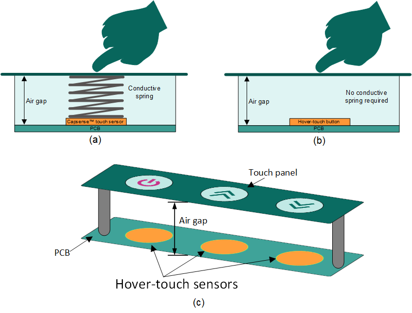
CAPSENSE hover-touch sensor applications
A hover-touch sensor is a capacitive touch button with the overlay elevated from the PCB. This implementation eliminates the need for the gap to be bridged using a conductive material (typically a spring or conductive foam). Additionally, this reduces the overall construction cost.
CAPSENSE™ hover-touch sensors can be used in several
home appliances
like:
Washing machines
Microwave ovens
Refrigerators
Air conditioners
Figure 3.
Advantage of using hover-touch button
Designing the CAPSENSE hover-touch hardware
This section describes the various hardware aspects that need to be considered when designing the hover touch sensor buttons.
See the
Supported devices
section for a list of compatible parts.
Air gap distance
Air gap distance (L
air
) is the primary consideration when designing a hover-touch button. Depending on the usecase and project, this requirement must be defined first. It represents the distance between the hover-touch sensor pad and the overlay surface that will be touched.
Figure 4.
Air gap between the hover-touch button and finger touch
Hover-touch button size
Hover-touch button size refers to the dimensions of the conductive pad that forms the touch sensor. The size of the button directly affects the maximum distance from which the hover-touch button can detect a contact. Larger buttons can detect touch from greater distances, while smaller buttons are limited to shorter distances.
The thumb rule is that the button size should at least be equal to the air gap distance. For example, if the air gap distance is 10 mm, the radius of a round button should be at least 10 mm.
Figure 5.
Size of the hover-touch button with respect to the air gap
Spacing between the hover-touch buttons
This parameter is crucial to ensure that each button can function without interfering with its neighboring buttons. Due to the high sensitivity of hover-touch buttons, placing two buttons too close together can cause one button to inadvertently trigger the other (crosstalk).
To prevent crosstalk, there should be ample space between the buttons. The recommended spacing between the buttons is equal to the button size itself. For example, if a round button has a diameter of 10 mm, the adjacent button should be at least 10 mm away from the edge of the first button, as shown in
Figure 6
.
Figure 6.
Spacing between the hover-touch buttons
Impact of nearby conductive objects
Nearby conductive objects can absorb a part of the electrical field, thereby reducing the detection range of the hover-touch sensors. Coupling of sensor electric field lines to nearby conductive/ground objects increases the sensor’s parasitic capacitance (C
P
) and consequently decreases the sensitivity of the hover-touch sensors.
To mitigate this impact:
Ensure that the conductive object is placed from the sensor
A shield is used between the object and the sensor. If feasible, use the object as a shield
The concept of shielding is outlined in Section
Layout guidelines
.
Directionality
Due to the highly sensitive nature of a hover-touch sensor, it can detect touches from unintended directions. Implementing directional sensing in an end system poses a significant challenge, as it relies on factors such as overall enclosure design, hardware components, and PCB layout.
The placement of a ground plane at the bottom of the sensors removes the possibility of unintended touches coming from below and achieves directional sensitivity in hover-touch sensors. Since the ground plane can decrease the sensor’s sensitivity, it must be placed with some separation from the sensor PCB. The optimal distance depends on various system factors and requires testing on the actual system to determine the best distance.
However, it is recommended to keep the separation at least 30% of the air gap as shown in
Figure 7
. The GND plane separation can be increased gradually if the desired sensitivity from the top side is low.
Figure 7.
Spacing between PCB and GND plane
shows a real-time example of a hover-touch sensing stack-up, including the PCB, ground plane, and overlay.
Figure 8.
The stack-up of the layers of the hover-touch sensing system
Note:
In systems that include a ground chassis, the ground plane is not required, as the ground chassis can fulfill the same function.
Layout guidelines
Layout guidelines for hover-touch sensors are similar to designing the CSD capacitive button sensors. For details, refer to Section 7.4 and Section 2.5.1.2 of
AN85951 - PSOC™ 4 and PSOC™ 6 MCU CAPSENSE™ design guide
.
Additionally, keep the following guidelines in mind:
Trace length: The lesser the length of the traces running on the PCB from the microcontroller GPIO to the hover-touch sensor pads, the better the sensitivity of the hover-touch sensors. Hence, it is recommended to minimize the sensor trace length
Shielding: The stray parasitic capacitance (Cp) of each sensor directly impacts the sensitivity of the hover-touch sensors. The Cp can increase due to nearby ground planes, ground traces, idle electrodes, etc. This high Cp decreases the sensitivity of the hover-touch sensors
To keep the Cp of the hove- touch sensor low, shielding is necessary. A shield is implemented by pouring a hatch-patterned copper around the hover-touch sensor and driving this shield with the signal that is identical to the hover-touch scanning signal. This shield can be driven with a dedicated GPIO, which is configured while developing the firmware.
It is recommended to shield the hover-touch sensor all around to achieve high sensitivity. The minimum gap between the hover-touch button and the shield should be 1 mm.
Figure 9
illustrates placing the shield around the hover-touch sensors.
Figure 9.
Spacing between PCB and GND plane
Noise tolerance
CAPSENSE™ hover-touch sensors are susceptible to noise because of their large sensor area and high sensitivity setting. High noise makes it difficult to achieve a good signal-to-noise ratio (SNR) (typically greater than 5:1), which is required for the hover-touch sensing system.
lists the common sources that contribute to noise in hover-touch sensing and their respective recommended mitigation techniques.
Noise source | Examples | Recommended noise mitigation technique |
|---|---|---|
PWM driven devices | LEDs, motors |
|
Switching power converter | AC-DC, DC-DC, DC-AC | |
High-speed communication interfaces | USB, Ethernet |
|
AC supply lines | Relays and switches |
|
Design considerations
Parameter | Recommendation |
|---|---|
Button Size | Greater or equal to air gap |
Button Spacing | Greater or equal to air gap |
Ground plane separation | Greater than 30% of air gap |
Developing the CAPSENSE hover-touch system firmware
This section assumes that the user is familiar with PSOC™ 4 devices, CAPSENSE™ technology, CAPSENSE™ Middleware Library, including the CAPSENSE™ Configurator, and Tuner software tools. For more information, refer to
Associated content
.
The code example
PSOC™ 4: MSCLP CAPSENSE™ Hover Touch 4
helps learn how to develop the firmware for the hover-touch system.
Prerequisites:
Install ModusToolbox™
Hover-touch tuning guidelines
The primary tuning guidelines are mentioned in the Tuning Procedure section of the code example
PSOC™ 4: MSCLP CAPSENSE™ Hover Touch
. The code example is tuned for the kit(s) mentioned in Section
Associated content
. However, for hover-touch, there are a few additional considerations to ensure optimal sensitivity and SNR.
Number of sub conversions (Nsubs): This is the primary parameter that influences the signal strength, sensitivity, and effective SNR of the hover-touch sensors. Higher the Nsubs, higher the SNR and sensitivity. Hover-touch applications require high sensitivity, and adjusting Nsubs plays a significant role in achieving this. However, increasing Nsubs also increases the scan time, hence impacting the response time of the hover-touch sensors. Fine-tuning this parameter is essential to reach an optimal case with a decent SNR and a good response time
CDAC Boost: This parameter can also be used to increase the signal strength. It can further amplify the signal when increasing the Nsubs is not sufficient and a higher signal level is required. Note that while CDAC Boost increases the signal strength, it also raises the noise level. Therefore, it is essential to fine-tune this parameter alongside Nsubs to find the optimal balance between signal strength and noise
Filters: A significant way to reduce noise is to enable filters, which greatly enhances the SNR, making the sensing robust and reliable
The CAPSENSE™ ecosystem features the following types of filters:
Hardware filters: CIC2, HW-IIR
Software filters: SW-IIR, Average, Median
For details of how the above filters work and affects the signal, refer to Table 10 of the AN85951 - PSOC™4 and PSOC™ 6 MCU CAPSENSE™ design guide. To enable the filters, refer to the section Fine tune for required SNR of the code example PSOC™ 4: MSCLP CAPSENSE™ Hover Touch
While filters can improve noise reduction, they can also increase the response time, potentially making the hover-touch buttons less responsive. A good balance between noise reduction and response time is very important while enabling the filters
Thresholds: When the appropriate SNR is achieved with a decent response time, thresholds are required to be set to determine the trigger points for touch detection. Tune the thresholds so that all intended button touches are properly triggered without being affected by the other buttons.
Due to the highly sensitive nature of hover-touch sensors, they tend to get triggered by touch on other neighboring hover-touch buttons, commonly called as cross talk. Cross talk is common and should not be treated as a problem. Fine-tuning the thresholds can effectively eliminate cross talk, ensuring clean and intended button triggering
Associated content
The following section provides the supporting resources relevant to this application note.
Supported devices
Supported kits
Online resources
CAPSENSE™ sensing controller webpage
ModusToolbox™ software help on Github
AN79953 – Getting Started with PSOC™ 4
Getting Started with CAPSENSE™
PSOC™ 4 and PSOC™ 6 CAPSENSE™ design guide
Eclipse IDE for ModusToolbox™ user guide
ModusToolbox™ CAPSENSE™ Configurator user guide
ModusToolbox™ CAPSENSE™ Tuner user guide
CAPSENSE™ Middleware Library Documentation
References
Infineon Technologies AG: AN64846 Getting Started with CAPSENSE™. Rev AA; Available online
Infineon Technologies AG: AN85951 PSOC™ 4 and PSOC™ 6 MCU CAPSENSE™ Design Guide. Rev AG;
Available online
Infineon Technologies AG: AN92239 Proximity sensing with CAPSENSE™; Available online
Revision history
Document revision | Date | Description of changes |
|---|---|---|
** | 2025-02-14 | Initial release |
*A | 2025-03-24 | Template updated Updated the supported device and kit in this release |