AN239805 Liquid-level sensing with PSOC™ 4 CAPSENSE
About this document
Scope and purpose
This application note shows how to use PSOC™ 4 MCUs with the 5th Generation CAPSENSE™ technology and capacitive sensors to measure the level of water-based liquids in nonconductive containers. Sensors located on the container exterior provide real-time reporting of liquid fill level without liquid contact. This solution is also capable of rejecting foam present on the surface of the liquid. This application note covers the use of the CAPSENSE™ Middleware Library in ModusToolbox™ to design sensors and enable robust liquid-level sensing.
Intended audience
This document is intended for engineers who need to design a liquid-level sensing solution using capacitive sensing.
Note:
This application note is for advanced users of CAPSENSE™ technology. If you are new to CAPSENSE™ technology, see Getting started with CAPSENSE™ application note. For more information on CAPSENSE™ in PSOC™ 4 and PSOC™ 6 devices, see PSOC™ 4 and PSOC™ 6 MCU CAPSENSE™ design guide.
Introduction
Liquid-level sensing (LLS) detects the level of liquid in a container. The types of liquid-level sensors include: capacitive, mechanical float, inductive, magnetic, Hall effect, optical, acoustic density, and ultrasonic. This application note describes the implementation of capacitive liquid-level sensing, which includes the design of the sensors, the calibration procedure, and the usage of the CAPSENSE™ Middleware Library to enable liquid-level sensing in a solution. This application note describes capacitive sensing liquid-level measurement, which provides noncontact, low-cost, low-power liquid-level measurement, and focuses on areas that differ from the traditional finger-touch applications using CAPSENSE™.
Note:
No two applications are the same and the design rules provided do not have hard limits unless specifically stated. Use the provided design recommendations as guidance and perform validation under your application conditions.
Infineon’s 5
th
Generation CAPSENSE™ technology enables high-resolution liquid-level measurement with a resolution of 1 mm. Liquid-level sensing is provided through the use of CAPSENSE™ Middleware Library provided with ModusToolbox™. CAPSENSE™ Middleware Library provides easy-to-use firmware and software interfaces to enable liquid-level measurement through the CAPSENSE™ hardware on the supported PSOC™ 4 devices. For more information, see
Supported devices
.
Features
The liquid-level sensing solution has the following features:
Non-contact measurement, which avoids corrosion, contamination, and cleaning difficulties
Accurate and high resolution liquid-level sensing
Foam rejection to correctly measure the level of a target liquid, even in the presence of foam
Guided sensor design and calibration using the CAPSENSE™ Middleware Library
CAPSENSE
Capacitive liquid-level sensors are conductive pads or traces laid on a nonconductive material, such as PCB, plastic, or glass. The intrinsic capacitance of the PCB trace, pads, and other sensor connections is called the sensor parasitic capacitance (C
P
), as shown in
Figure 1
.
When a target object such as water approaches the sensor, a small amount of liquid capacitance (C
L
) is added to the C
P
. Liquid-level sensing involves measuring the increased capacitance when water is near the sensor.
Figure 1. Capacitance and electric field of a capacitive liquid-level sensor (a) and added capacitance (CL) when the liquid approaches a capacitive sensor (b)
The 5
th
Generation CAPSENSE™ block contains a converter that is similar to a delta sigma ADC. In the LLS system, the CAPSENSE™ block drives a signal onto the sensor. The driven signal generates a current; the voltage across the capacitance is sampled by the converter and converted into a digital value that is known as raw counts.
Environmental effects
There are several factors that impact the accuracy of a liquid-level sensing system, causing changes in the capacitance of the sensor(s) that result in reduced accuracy. Some of the most critical effects are temperature and mechanical variation.
Temperature
Temperature fluctuations during operation can have a significant impact on the capacitance of the system. These impacts are largely mitigated by the LLS solution; however, careful consideration and correct calibration procedures must still be followed to ensure reliable performance across temperatures.
To ensure your system functions well across temperature:
Calibrate your system for your typical temperature liquid by following the steps mentioned in the Liquid-level factory calibration procedure section
Fill the tank with liquid at a hot or cold relative temperature and observe the output liquid level
A temperature gradient exists as the liquid in the tank slowly settles to ambient. This temperature gradient may cause a minor reduction in accuracy but will ultimately resolve as the liquid mixes and the temperature becomes uniform.
If the accuracy of the liquid level is not within an acceptable range across temperature, re-do the typical liquid temperature calibration, but with a small settling time of a few seconds after adding the liquid before “logging data”. This allows the liquid temperature to become relatively uniform.
Mechanical variations
Mechanical variations within the system can take many forms but all result in a change to the sensors C
P
. The are two types of mechanical variations:
Static variation is generally caused by manufacturing tolerances in the sensor assembly, PCB, and sensor alignment to the liquid container. If understood and controlled, static variations are compensated for during manufacturing with the calibration operation described in the Liquid-level factory calibration procedure section
Dynamic variation is caused by changes during operation. These changes often show themselves as changes to CP by changing the sensor’s dimensions. Like temperature changes, dynamic variation is difficult to compensate for. It is best to design the system to minimize dynamic mechanical variation effects on the sensors
Common mechanical variations:
Change in the distance between the capacitor plates, where the first plate is the sensor and the second plate is the liquid surface. This can be caused by air bubbles in the adhesive used to attach the sensors to the container — the bubbles grow and shrink with air pressure
The sensors are not directly attached to the liquid container, allowing a changing air gap between the container wall and the sensor substrate. This is a typical case for the removable tanks
To reduce the impact of such factors, ensure that there are no air bubbles present and the mechanical design is sufficient to maintain accurate sensor alignment.
Parasitic capacitance
Parasitic capacitance (C
P
) is the capacitance that results from the electric field between the sensor (including the sensor pad, traces, and vias) and other conductors in the system such as ground planes, traces, and any metal in the product’s chassis or enclosure. The CAPSENSE™ block measures the total capacitance, which is the total of parasitic and liquid capacitance (CTOTAL= CP+CL) within the limits of its dynamic range. In systems where CPis larger, the parameter of interest (CL) is proportionally smaller. Additionally, as more of the electric field couples to the ground by increasing C
p
, less of the field couples to the liquid, which reduces C
L
. The combined effect reduces the system sensitivity to liquid presence and therefore, total system accuracy.
The main components of parasitic capacitance in CAPSENSE™ designs are trace capacitance and sensor capacitance. C
P
is a nonlinear function of sensor size, trace length, trace width, and trace-to-trace spacing. There is no simple relation between C
P
and the PCB layout features, but general principles do exist. To reduce the development time of sensor patterns, ModusToolbox™ provides a graphical interface that automatically generates sensor layout based on known best practices. Additionally, a more detailed layout guidance is provided in the
Sensor design
section.
System overview
This section provides a high-level overview of the system components and how they are used during development and integration into a larger system.
A capacitive liquid-level sensing system has three key elements:
Capacitive sensor pattern
PSOC™ 4 with the 5th Generation CAPSENSE™ block
See the Supported devices section for a list of compatible parts.
Tank with liquid to sense
Block diagram
A typical liquid-level sensing system comprises the following:
Liquid in a container
Sensors
PSOC™ 4 device
Host controller
In this system, an array of capacitive sensors on a PCB affixed near the container is connected to the CAPSENSE™ block in the PSOC™ 4 device. The CAPSENSE™ technology detects the capacitive coupling of the liquid to the sensors. PSOC™ processes the capacitance data, calculates the level of liquid present in the container, and communicates the data to the host device.
Figure 2.
Liquid-level sensing system block diagram
Infineon provides several development tools, mentioned in
Software tools
to assist with the creation of an LLS system. These tools ease the calibration process and enable seamless tuning of an LLS system. Typically, the development process uses one of the supported PSOC™ 4 kits as well as the software tools provided as part of the CAPSENSE™ library. Hence, the high-level block diagram appears slightly different during development, which is described in the
System components
section.
System components
shows the high-level overview of the components required for developing and tuning of the liquid-level sensing system.
Figure 3.
Liquid-level sensing block diagram in the development phase
Liquid sensing hardware
The following system components are common in both development and production designs:
Liquid– The target liquid that is being sensed
Tank– The tank is the container where the liquid that is being sensed is present. The tank material must be non-metallic and non-conductive for compatibility with the LLS system. Additionally, the tank must have a wall thickness of 5 mm or lower
Level sensor
– The level sensor is the capacitive sensor array that capacitively couples to the liquid to detect the liquid level. The level sensor strip may either be a rigid or flexible PCB material. The design of the sensor must follow the guidance detailed in
Sensor design
. The liquid-level sensing solution provides a graphical tool called
Sensor Designer tool
that can generate a sensor pattern in
.dxf
format, simplifying the sensor design process
The level sensor must be affixed to the side of the tank. The system does not work with the sensor segments mounted on either the bottom or top of the tank.
PSOC 4 kit and PSOC 4 device
PSOC™
4 device:
A supported PSOC™ 4 device as listed in
Supported devices
The PSOC™ 4 device contains the CAPSENSE™ hardware that enables measurement of capacitance. The device also contains an MCU to enable the processing of the sensor data, and serial communication blocks (SCBs) to enable the communication to a host device over SPI, I2C, or UART
PSOC™ 4 kit:
One of the supported PSOC™ 4 kits as listed in
Supported kits
The PSOC™ 4 kit is designed to enable rapid evaluation and development of a project on PSOC™ 4. During the development of a liquid-level sensing solution, the sensor(s) can be connected to the I/O headers of a supported kit. A project created with the CAPSENSE™ Middleware Library in ModusToolbox™ can communicate with the onboard KitProg programmer/debugger to enable real-time viewing of sensing data and system calibration. The KitProg programmer/debugger is used to flash and debug the firmware via the SWD interface to the PSOC™ MCU. It also serves as a bridge between the PSOC™ MCU and CAPSENSE™ Tuner, communicating over I2C or UART
Software tools
ModusToolbox provides several tools for developing an LLS solution:
CAPSENSE™
Configurator:
Enables the configuration of the liquid-level sensing widget and selection of CAPSENSE™ hardware parameters
CAPSENSE™
Tuner:
Enables liquid-level calibration through a guided UI. It also enables run-time configuration of sensing parameters and visualization of sensor data
CAPSENSE™ Middleware Library:
The middleware can be used to develop liquid-level sensing applications and it provides APIs to simplify firmware development.
Sensor Designer:
Provides a graphical interface to design and generate liquid-level sensors in
.dxf
format
For more information on the software tools in the scope of the LLS solution, see
CAPSENSE™ LLS software
.
Sensor design
The LLS system requires carefully designed sensor patterns to avoid inaccuracies caused by variation, environmental impacts, and high parasitic capacitance. This section discusses the software tool packaged as part of ModusToolbox™ as well as the best practices for designing liquid-level sensors.
Sensor design best practices
Level sensor
The recommended design for a liquid-level sensor is a “segmented” pattern. It is composed of parallelograms arranged in a strip with ground pads on either side. A segmented sensor has parameters that can be configured for optimal performance, as
Figure 5
shows.
Figure 4.
Liquid-level sensor with labels
Generally, a liquid-level sensor should be designed such that the sensor height is equal to or slightly larger than the maximum level of liquid that is being detected. The sensor width should be between 30 mm and 60 mm.
The specific design of the level sensor depends on whether or not the liquid being detected is grounded.
A grounded liquid is directly coupled to the same system ground as the sensor array and often requires a grounded contact submerged in the liquid. A grounded liquid couples to the sensor strongly and induces a large liquid capacitance (C
L
).
An ungrounded liquid does not have a direct contact with the system ground, instead it capacitively couples to the ground on the external sensor through the wall of the tank material. The ungrounded liquid induces a smaller C
L
relative to the grounded liquid.
Sensor designer tool
The Sensor Designer tool is provided with the
ModusToolbox™ CAPSENSE™ and Multi-Sense Pack
, which will be installed automatically when installing ModusToolbox™ 3.5 or later, using
ModusToolbox™ Setup
. This can be accessed in any ModusToolbox™ project that uses a compatible device listed in
Supported devices
and enables the CAPSENSE™ Middleware Library. The tool provides a graphical interface with user-input options to design and generate a
.dxf
file containing an LLS sensor pattern.
Liquid Level x configuration
The
Liquid Level x
tab contains the calculator tool for generating a liquid-level sensor pattern, as
Figure 5
shows. This tab allows you to input several values, calculate sensor dimensions, and generate a
.dxf
file of the calculated pattern.
The UI elements numbered in
Figure 5
are as follows:
Generate DXF:
Generates a
.dxf
file containing the calculated sensor pattern. The
.dxf
file may be imported into CAD or EDA programs to enable rapid development of a PCB containing the sensor pattern
Save configuration:
Saves the input values and other calculated values that can be loaded with the
Load configuration
button
Load configuration:
Loads a previously saved sensor design
Figure 5.
Liquid Level x configuration
Level sensor design parameters
This section covers the user-configurable parameters that are used primarily to generate the design of the sensor.
Sensor height: The value for the total vertical height of the sensor in mm
Sensor width: The value for the total width of the sensor in mm
Liquid: Specifies the liquid as “grounded” or “ungrounded”
A grounded liquid has direct contact to the shared system ground through a submerged contact. In many systems, the liquid is ungrounded
Ground offset: The value for the spacing between the outer perimeter of the sensor and the ground pad in mm
Note:
Smaller spacing is suggested. The smallest spacing may be limited by the capabilities of PCB fabrication technology.
The following fields are automatically calculated by the tool. These fields can be edited by selecting the check box:
Number of Electrodes: The value for the total number of sensors. By default, this gets optimally calculated from the given sensor height. It can be changed by checking the checkbox next to the parameter. Reducing the number of electrodes from the recommended value might lead to lower accuracy. Increasing the number of electrodes might increase the accuracy, but at the cost of pins and power
Electrode width: The value for the width of the sensor electrodes in mm
Sensing pad gap: The value for the distance between adjacent electrode pads in mm, which is typically around 0.5 mm
Sensor-ground gap: The value for the distance between the outer edge of the electrode pads and the ground strips on the sides of the sensor in mm which is typically around 2 mm to 4 mm
Trace width: The value for the width of the traces that are routed to the sensors in mm
The minimum value supported by the PCB manufacturer is recommended
Trace gap: The value for the spacing between adjacent traces in mm
The minimum value supported by the PCB manufacturer is recommended
Via holes diameter: The value for the diameter of the vias that connect the trace to the top layer sensor in mm
Overlay stack-up: This segment enables the estimation of whether the overlay material between the sensor and the wall of the liquid container is acceptable. A greater overlay thickness and lower relative permittivity results in a decrease in capacitance coupled by the liquid with the sensor. Multiple overlays can be added, as long as the shown liquid capacitance remains higher than the recommended value
CAPSENSE LLS software
This section assumes that you are familiar with CAPSENSE™ Middleware Library, including the CAPSENSE™ Configurator and Tuner software tools. For more information on CAPSENSE™ Middleware Library and the software tools provided, see the
Online resources
section.
The liquid-level solution is enabled through the CAPSENSE™ Middleware Library provided with ModusToolbox™. To enable the software, create a project in ModusToolbox™ and import the latest version of the CAPSENSE™ Middleware Library. The CAPSENSE™ Middleware Library provides the API for enabling, configuring, scanning, and reading of the capacitive sensor data. ModusToolbox™ provides CAPSENSE™ Configurator and CAPSENSE™ Tuner that is used for configuring and reading LLS data.
For more details, see the
PSOC™ 4: MSCLP CAPSENSE™ liquid-level sensing
code example.
Liquid-level factory calibration procedure
The liquid-level processing function must be calibrated for each design. The calibration routine increases the accuracy of the solution and is guided by the CAPSENSE™ Tuner tool. Before calibrating, ensure that the liquid-level sensors are properly tuned following the guidance in the “Tuning Procedure” section of
PSOC™ 4: MSCLP CAPSENSE™ liquid-level sensing
code example.
If the system requires foam rejection, ensure that the “Foam rejection” option is enabled in the project before calibrating.
Figure 6.
Liquid-level calibration procedure
Level calibration
Prerequisites:
Ensure that the sensor data can be read
An additional foam rejection calibration process is required before the below mentioned liquid-level sensing sensor calibration process
Calibration procedure:
Navigate to the
Liquid Level Measurement
tab, as
Figure 7
shows.
Figure 7.
Liquid Level Measurement tab in CAPSENSE™ Tuner
Enter the measurement parameters for your tank, as Figure 8 shows.
Figure 8.
Liquid-level measurement parameters
Tank Height: The total height of the liquid to be measured in mm
Minimum resolution (height step): The minimum change in liquid depth you would like to measure.
Note that the amount of calibration data you need to collect is inversely proportional to this value. Lower minimum resolution values yield more data collection
Number of averaged samples per step:
The number of raw counts samples that are averaged to yield one data point while logging data. Higher values increase data logging time and accuracy
Note:
If the foam rejection is enabled, the
minimum resolution (height step)
and the
number of averaged samples per step
fields will become editable only after the
Step 4.a
of this section is completed.
Select
Disable CDAC auto-calibration
This prompts a notice stating “No CAPSENSE™ Configuration parameters may be changed during the calibration process and that any change in parameters will require re-calibration”. This prevents the device from performing the CDAC auto-calibration routine on device reset, effectively saving the current CAPSENSE™ parameters. Selecting
Yes
enables the calibration operation in CAPSENSE™ Tuner.
Figure 9.
Disable CDAC auto-calibration
Log data:
This step is required if the foam rejection is enabled else skip to Step b)
Keep the tank empty and click Log data
Figure 10.
Empty tank calibration for foam rejection
Fill the tank until it is half full, verify you are in the Half-Empty step and then click Log data again
Empty the tank completely and verify you are on the Empty step. Then click
Log data
The Empty step becomes dark green, as
Figure 11
shows
The logging status of the levels is color-coded as follows:
Dark green:
Logged level
Green:
Current level to log
White:
Levels yet to be logged
Figure 11.
Logging data for the "Empty” step
Fill the tank to the level that should be considered empty; this is the ‘0’ step. Wait a moment for the system to settle, then select
Log data
. Once logged, the color of level “0” changes from green to dark green
The addition of water introduces new capacitance and a temperature change that take a few seconds to settle. It is important to wait for a few seconds before logging data, otherwise the system may not calibrate correctly.
Note:
If the ‘0’ step and the 'Empty’ step are at the same level, leave the tank empty during this step.
Verify you are on height step 1 as shown in Figure 12. Fill the tank to the level configured in minimum resolution (height step). Log the data
Figure 12.
Progress bar showing that the current step is 1
For each subsequent step, fill the tank by the level indicated by
minimum resolution
and log data
Repeat until each step is complete (represented by a dark green color, as
Figure 13
shows).
Note:
You may skip steps by clicking
Next level
. This may reduce accuracy but reduces the total number of calibration steps needed.
You may also return to any level by selecting
Previous level
any number of times or by clicking directly on the level in the progress bar.
Figure 13.
Completed progress bar
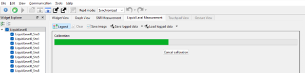
After data has been logged for the final step, select
Finish calibration
Wait for the calibration process to complete, as
Figure 14
shows.
Figure 14.
“Finish calibration” progress bar
After the calibration is completed, new graphs are displayed, which show the accuracy and error of the calibration based on the input data that was logged in
Step 4
.
Select Apply to Project, then disconnect from the tuner, and program the part to apply the calibration to the device
Empty the tank
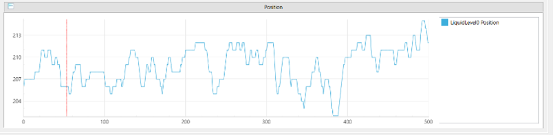
Reconnect to the tuner and navigate to the Graph View tab
Observe the liquid level displayed in the
Position
graph
Figure 15.
“Apply to project” button and the “Position” graph
Fill the tank by a known amount and check if the position closely matches the expected value
The expected position value is defined by
Equation 1
:
Position
Max
:
The liquid-level sensor widget’s maximum Level parameter
Minimum resolution:
Minimum resolution set in the tuner
Tank height:
Tank height value set in the tuner
LiquidLevelCurrent:
The current level of liquid present in the container
If the position is not accurate, re-calibrate your system following the procedure in
Step 4
If the noise levels in the position output are not acceptable, for example as
Figure 16
shows, configure the software filters for your system in CAPSENSE™ Configurator:
Figure 16.
Jittery position output
Disconnect from CAPSENSE™ Tuner and open
CAPSENSE™ Configurator
Enable raw count filtering as shown in Step 4 of “Fine tune for required SNR” in
PSOC™ 4: MSCLP CAPSENSE™ liquid-level sensing
code example. Often times, raw count filtering is enough to reduce toggling and position noise
Enable Position filters. Navigate to and configure the filters as needed, as Figure 17 shows
Table 1.
Raw count filters and its functions
Name
Function
IIR filter
Programmable filter that behaves as a low-pass filter. Lower coefficient values have a lower cutoff-frequency and reduce response time
Median filter
Averages three samples to remove noise spikes
Average filter
Averages two samples to remove periodic noise
Jitter filter
Eliminates toggling noise
Figure 17. Enabling level filters in CAPSENSE™ Configurator and the clean position signal observed
Foam rejection calibration
The foam rejection widget contains an additional parameter – the Foam correction coefficient that determines how much compensation is applied to the level detection to remove signal from the foam.
The foam correction coefficient is given by the following equation:
LevelFoam= The level displayed by the CAPSENSE™ Tuner for the foam rejection widget
LevelKnown= The level of the target liquid known by measurement with an external tool
LevelLiquid= The level displayed by the CAPSENSE™ Tuner for the base liquid-level widget
To calculate the foam correction coefficient, ensure that you have correctly followed the process detailed in
Level calibration
. Then, perform the following steps:
Fill your tank to a known target level without adding any surfactants
Add a surfactant (soap, cleaner detergent, or other bubbly liquid) and vigorously stir the mixture to generate a layer of bubbles on the surface of the liquid
In CAPSENSE™ Tuner, connect, start, and navigate to the Position graph tab
Enable both the base liquid-level widget and the foam rejection widget and view the level data, as Figure 18 shows
Figure 18. Tuner data showing the position of the liquid-level base widget (blue); foam rejection enabled widget (purple)
In the example in Figure 19, the calculated Foam correction Coefficient is as follows:
Level
Foam
= 300, Level
Known
= 290, Level
Liquid
= 347, Coeff
foam
= 54
Change the Foam correction Coefficient in the widget and apply the change to your device and project
Figure 19.
Foam correction coefficient widget in CAPSENSE™ Tuner
Ensure that the position value for the FR widget now matches the actual level of liquid
Associated content
The following section provides the supporting resources relevant to this application note.
Supported devices
Supported kits
Online resources
See the following documents to get started with PSOC™ 4 devices, CAPSENSE™ technology, and ModusToolbox™:
CAPSENSE™ sensing controller webpage
ModusToolbox™ webpage
ModusToolbox™ software help on GitHub
AN79953 – Getting Started with PSOC™ 4
Getting started with CAPSENSE™
PSOC™ 4 and PSOC™ 6 CAPSENSE™ design guide
Eclipse IDE for ModusToolbox™ user guide
ModusToolbox™ CAPSENSE™ Configurator user guide
ModusToolbox™ CAPSENSE™ Tuner user guide
CAPSENSE™ Middleware Library Documentation
References
Infineon Technologies AG: AN64846 Getting started with CAPSENSE™;
Available online
Infineon Technologies AG: AN85951 PSOC™ 4 and PSOC™ 6 MCU CAPSENSE™ design guide;
Available online
Revision history
Document revision | Date | Description of changes |
|---|---|---|
** | 2024-06-25 | Initial release |
*A | 2024-12-09 | Updated the sensor designer tool, images, and factory calibration process |
*B | 2025-01-10 | Updated GitHub link of the CE |
*C | 2025-02-14 | Updated Foam Rejection Calibration Process |
*D | 2025-03-21 | Template update Updated the Supported devices and Supported kits Updated the following figures: to Figure 11 |
Trademarks
PSOC™, formerly known as PSoC™, is a trademark of Infineon Technologies. Any references to PSoC™ in this document or others shall be deemed to refer to PSOC™.