AN241195 Manufacturing test recommendations for PSOC™ 4 CAPSENSE designs
About this document
Scope and purpose
This document provides guidelines for system-level manufacturing tests for CAPSENSE™ designs based on PSOC™ 4 CAPSENSE™ controllers.
Intended audience
This document is intended as a resource for engineers who are new to CAPSENSE™ design and manufacturing test for PSOC™ 4, providing them with the necessary information to get started with designing and testing CAPSENSE™ based systems using PSOC™ 4 devices.
Introduction
CAPSENSE™ touch-sensing solutions are increasingly replacing traditional mechanical buttons, sliders and knobs in modern designs. As these applications become commonplace it becomes important that these designs are tested during production to ensure the quality of the end product. This document provides guidelines in this regard.
There are two parts to these CAPSENSE™ manufacturing tests:
Self-test library functions to perform the tests.
A a library of self-test routines is available in the CAPSENSE™ Middleware to support manufacturing testability. For devices with flash memory limitations, these self-test library functions can be incorporated into a separate test firmware for manufacturing tests. This is only applicable if reprogramming the device in production line is feasible. In such cases, program the device with the self-test firmware first to execute the manufacturing tests. Once the system passes the basic manufacturing tests, reprogram the device with the final application firmware in the production line
Host interface that initiates the tests and reads the test results to analyze parameters.
For the host interface portion of the tests, one of the communication protocols supported by PSOC™ (such as I
2
C, UART, SPI, etc.) should be used by the host to communicate with the PSOC™. This enables the host to initiate individual tests and read the test results
These tests help in identifying the the following possible issues:
Fault conditions such as electrically opened or shorted sensors.
For example, the PCB track may be broken or shorted to other nodes in the system
Incorrect value of external capacitance.
CAPSENSE™ also requires external capacitor C
MOD
for selfcapacitance sensing. The recommended value of C
MOD
is 2.2 nF. These capacitors forms an integral part of the CAPSENSE™ block, and it is important to ensure they are soldered properly on the board for the CAPSENSE™ block to function efficiently
Self and mutual capacitance values that are out of range.
For example, the following range is defined for PSOC™ 4000T:
Table 1.
Capacitance Range
Parameter
Description
Min
Max
Unit
CIN_Self
Input capacitance range for self-capacitance
2
200
pF
CIN_Mutual
Input capacitance range for mutual-capacitance
0.5
30
pF
Similarly, for other devices check the respective datasheet.
Schematic and layout errors
Failure to adhere to the layout guidelines can cause increased variability between parasitic and mutual capacitance, , which may lead to calibration failures and potentially result in a non-linear centroid response in slider or touchpad applications.
The schematic and layout of the design can also be validated before manufacturing, using simulation tools like CapExt, which is used to analyze and mitigate capacitance variations in a design. It helps to identify potential issues with parasitic and mutual capacitance, which can affect the performance and accuracy of a system, particularly in applications such as touchpads and sliders.
The CapExt tool can be used to:
Analyze the capacitance of a design and identify potential issues
Optimize the layout to minimize capacitance variations
Predict the impact of capacitance variations on system performance
Validate the design and ensure that it meets the required specifications
In all the above conditions BIST function returns measured capacitance which can be compared against expected capacitance for the given parameter.
Factory testing guidelines (Post manufacturing)
The important elements to be tested for CAPSENSE™ designs are the following:
CRC of the parameter set
Rawcount measurement
Pin open and short tests
Electrode capacitance measurement
Slot sensor capacitance measurement
Shield electrode capacitance measurement
External capacitance used as a part of CAPSENSE™ system:
Modulation capacitor: CMOD for self-capacitance sensing
Shield capacitor tests: If shield is enabled and scanned with shield signal instead of ground
VDDA measurement
To gain a more comprehensive understanding of the CAPSENSE™ system's performance, collect the following additional data:
SNR
: Measure the signal-to-noise ratio to assess the system's signal quality and noise immunity.
Linearity (for Sliders and Touchpads)
: Assess the system's ability to provide a linear response to user input, ensuring accurate and consistent performance
The detailed description of these tests are given in the following section.
List of tests supported by BIST
Cy_CapSense_RunSelfTest()
It is a high-level function that performs various self-tests on all enabled widgets and sensors in the project. The required set of tests can be selected using the bit-mask in the testEnMask parameter.
Note:
All the measured values are stored in the
cy_stc_capsense_context_t
structure.
The function to be included in the code :
cy_en_capsense_bist_status_t Cy_CapSense_RunSelfTest (uint32_t testEnMask,cy_stc_capsense_context_t * context)
Parameters | testEnMask | Specifies the tests to be executed, where each bit corresponds to one test. The function can be launched with any combination of the available tests.
|
context | The pointer to the CAPSENSE™ context structure cy_stc_capsense_context_t. | |
Returns | Returns a bit-mask with a status of execution of the specified tests:
|
To execute a single-element test (i.e., for one widget or one sensor), the low-level functions are explained in detail in this document.
External capacitance measurements
This function measures the capacitance (in picofarads) of the specified CAPSENSE™ integration (external) capacitor and must not be called while the CAPSENSE™ Middleware is busy. The function is blocking, meaning it waits for the measurement to complete before returning to the caller.
The maximum capacitance that can be measured is 25 nF. The measurement accuracy is up to 30% for the fifth-generation low-power CAPSENSE™ HW block. The measurement resolution is 10 bit, which corresponds to the maximum capacitance specified by the
maxCapacitance
parameter. The bigger the specified maximum capacitance is, the bigger the capacitance value is for one measured count. It is recommended to set the maximum capacitance to be twice as large as the nominal capacitance to be measured. For example, if the nominal CMOD value is 2.2 nF, the
maxCapacitance
parameter should be set to 4 nF and 5 nF.
The lower level function to be included in the code to measure these capacitors:
cy_en_capsense_bist_status_t Cy_CapSense_MeasureCapacitanceCap(cy_en_capsense_bist_external_cap_id_t integrationCapId, uint32_t* ptrValue,uint32_t maxCapacitance,cy_stc_capsense_context_t* context)
Parameters | integrationCapId | Specify the ID number of the external capacitor to be measured:
|
ptrValue | The pointer to the result of the capacitance value measurement in pF | |
maxCapacitance | Maximum expected value of the measured capacitance in nanofarads is in the range from 1 to 25 nF. Note: It is recommended to specify the maximum capacitance to be twice as large as the nominal capacitance being measured. For example, if the nominal Cmod value is 2.2 nF, the maxCapacitance parameter is set to 4 nF and 5 nF. | |
context | The pointer to the CAPSENSE™ context structure | |
Return |
|
To measure all the available capacitors, the Cy_CapSense_RunSelfTest() function can be used with the
CY_CAPSENSE_BIST_EXTERNAL_CAP_MASK
mask.
Electrode capacitance measurement
This function measures the sensor capacitance for CSD widgets or the electrode capacitance for CSX widgets and returns the measurement status. If the specified sensor is a ganged sensor, the capacitance is measured for all the electrodes that belong to this sensor , ganged together. This function must not be called while the CAPSENSE™ Middleware is busy with another scan.
The lower level API to run this test is:
cy_en_capsense_bist_status_t Cy_Capsense_MeasureCapacitanceSensorElectrode (uint32_t widgetId,uint32_t eltdId, cy_stc_capsense_context_t* context)
Parameters | widgetId | Specifies the ID number of the widget. |
eltdId | Specifies the ID of the electrode within the widget. | |
context | The pointer to the CAPSENSE™ context structure | |
Return | Status of the test execution:
|
It is possible to execute the test for all widgets/sensors using the CapSense_RunSelfTest() function with the
CY_CAPSENSE_BIST_ELTD_CAP_MASK
mask.
Note:
It measures the self capacitance (C
p)
of sensors. However, mutual capacitance (C
m)
cannot be measured using this function.
Sensor slot capacitance measurement
The function measures the self capacitance C
p
for CSD widgets and the mutual capacitance C
m
for CSX widgets. This function must not be called while the CAPSENSE™ Middleware is busy with another scan.
The lower level function to be included in the code to measure these capacitance:
cy_en_capsense_bist_status_t Cy_CapSense_MeasureCapacitanceSlotSensors (uint32_t slotId,uint32_t skipChMask,cy_stc_capsense_conext_t* context)
Parameter | slotId | Specifies the ID number of the slot to measure sensor capacitance. The slot ID should be in the appropriate range, depending on the number of scan slots that are configured. |
skipChMask | Specifies the mask to skip some channels during the slot sensor capacitance measurement. If the bit N in the skipChMask is set to 1, the channel N will be excluded from measuring and all its pins will be set to the inactive sensor connection state. Note: For fifth-generation low power CAPSENSE™ the function can be called with value 0u. | |
context | The pointer to the CAPSENSE™ context structure . | |
Return | Returns a status of the test execution:
|
It is possible to execute the test using the CapSense_RunSelfTest() function with the
CY_CAPSENSE_BIST_SNS_CAP_MASK
mask.
Shield electrode measurement
This function measures the capacitance of all shield electrodes. It checks if there is any CSD widget in the project and if the shield is enabled. If a shield channel consists of multiple electrodes, the total capacitance of all the shield electrodes is measured.
By default, all CAPSENSE™ sensors (electrodes) that are not being measured are set to the GND state. The inactive state can be changed during runtime using the Cy_CapSense_SetInactiveElectrodeState() function. When the inactive sensor (electrode) connection is set to the
CY_CAPSENSE_SNS_CONNECTION_SHIELD
state, all CAPSENSE™ electrodes are connected to the shield, and the total capacitance is measured.
The lower level function to be included in the code to measure these capacitance:
cy_en_capsense_bist_status_t Cy_Capsense_MeasureCapacitanceSensorElectrode (uint32_t widgetId,uint32_t eltdId, cy_stc_capsense_context_t* context)
Parameter | skipChMask | Specifies the mask to skip some channels during the slot sensor capacitance measurement. If the bit N in the skipChMask is set to 1, the channel N will be excluded from measuring and all its pins will be set to the inactive sensor connection state . Note: For fifth-generation low power CAPSENSE™ the function can be called with value 0u. |
context | The pointer to the CAPSENSE™ context structure . | |
Return | Returns a status of the test execution:
|
This test can be executed using the CapSense_RunSelfTest() function with the
CY_CAPSENSE_BIST_SHIELD_CAP_MASK
mask.
For clarity, let’s consider an example where the configuration includes:
1 CSD button (C)
2 shields (A and B )
Inactive sensor connection : Shield
In this case, Cy_CapSense_MeasureCapacitanceShieldElectrode() function will return the sum total of Cp (A+ B+C).
Note:
To check the Cp value of a specific shield electrode (e.g., Shield A or Shield B), configure the shield pin as a CSD widget and use the Cy_CapSense_MeasureCapacitanceSensorElectrode() function.
CRC of the parameter set
Frequently, the parameters used for CAPSENSE™ scanning are made programmable via I
2
C. In such cases, it is recommended to add a CRC (Cyclic Redundancy Check) to the parameter block set and to add a command for calculating and reporting the CRC of the parameter block. This can be used to verify the integrity of the parameters during tests or after updating them.
This function validates the data integrity of the
cy_stc_capsense_widget_context_t
data structure for the specified widget by calculating the CRC and comparing it with the stored CRC value of that widget.
The lower level function to be included in the code to verify CRC:
cy_en_capsense_bist_status_t Cy_Capsense_CheckCRCWidget (uint32_t widgetId, cy_stc_capsense_context_t* context)
Parameter | widgetId | Specifies the ID number of the widget. A macro for the widget ID can be found in the CAPSENSE™ configuration header file (cycfg_capsense.h) defined as CY_CAPSENSE_<WidgetName>_WDGT_ID. |
context | The pointer to the CAPSENSE™ context structure . | |
Return | Returns a status of the test execution:
|
It is also possible to execute this test using Cy_CapSense_RunSelfTest() function with the
CY_CAPSENSE_BIST_CRC_WDGT_MASK
mask as an input.
Rawcount measurement
The function checks whether the raw count is within the limits defined in the function arguments. It should be called after sensor scanning and processing, as processing modifies the sensor raw counts. Do not call this function before processing.
Note:
Verify that raw counts of each sensor are approximately equal to 'raw count calibration level set' (± 5%) of the MaxCount.
The lower level function to be included in the code to check the limit:
cy_en_capsense_bist_status_t Cy_CapSense_CheckIntegritySensorRawcount (uint32_t widgetId, uint32_t sensorId, uint16_t rawcountHighLimit, uint16_t rawcountLowLimit, cy_stc_capsense_context_t* context)
Parameter | widgetId | Specifies the ID number of the widget. |
sensorId | Specifies the ID number of the sensor within the widget. | |
rawcountHighLimit | Specifies the upper limit for the widget/sensor raw count. | |
rawcountLowLimit | Specifies the lower limit for the widget/sensor raw count. | |
context | The pointer to the CAPSENSE™ context structure . | |
Return | Returns a status of the test execution:
|
It is not possible to execute this test using the CapSense_RunSelfTest() function.
Pin open and short tests
In many CAPSENSE™ designs, it is often necessary to verify whether the pins are shorted to GND, VDD, or other sensors.
This function performs several sub-tests to ensure that the specified sensor is not electrically shorted and is in good condition to reliably detect user interactions. This test can only be executed if the CAPSENSE™ is in the IDLE state. The function must not be called while the CAPSENSE™ Middleware is busy.
The function checks if the specified sensor is shorted to:
GND
VDD
Other GPIOs used by CAPSENSE™ (such as sensors, Tx, Rx, shield electrodes, and external capacitors)
Other non-CAPSENSE™ GPIOs (only if they are configured in a strong high or low state during the test execution)
The absolute resistance of an electrical short must be less than 1500 ohms, including all series resistors on a sensor, for a short to be detected to GND, VDD, or GPIOs. For example, if a series resistor on a sensor is 560 ohms (as recommended) and the sensor is shorted to another sensor, the function can detect a short with a resistance of up to 380 ohms, as there are two 560 ohms resistors between the shorted sensor GPIOs
Note:
To detect an electrical short or fault condition with resistance higher than 1500 ohms, the Cy_CapSense_MeasureCapacitanceSensor()(4th Generation) or the Cy_CapSense_MeasureCapacitanceSensorElectrode() (5th Generation) function can be used, since the fault condition impacts the measured sensor capacitance.
The lower level function to be included in the code :
cy_en_capsense_bist_status_t Cy_CapSense_CheckIntegritySensorPins( uint32_t widgetId, uint32_t sensorId, cy_stc_capsense_context_t* context)
Parameter | widgetId, | Specifies the ID number of the widget. |
sensorId | Specifies the ID of the sensor within the widget to be tested. | |
context | The pointer to the CAPSENSE™ context structure . | |
Return | Returns a status of the test execution:
|
To check all the project sensors at once, use the Cy_CapSense_RunSelfTest() function with the
CY_CAPSENSE_BIST_SNS_INTEGRITY_MASK
mask.
If a short is detected, this function updates the following statuses:
The widget ID is stored in the .shortedWdId field of the
cy_stc_capsense_bist_context_t
structure
The sensor ID is stored in the .shortedSnsId field of the
cy_stc_capsense_bist_context_t
structure
The
CY_CAPSENSE_BIST_SNS_INTEGRITY_MASK
bit is set in the
.testResultMask
field of the
cy_stc_capsense_bist_context_t
structure
If
CY_CAPSENSE_BIST_SNS_INTEGRITY_MASK
is already set due to a previously detected fault on any of the sensor, this function does not update the .shortedWdId and .shortedSnsId fields. For this reason, clear the
CY_CAPSENSE_BIST_SNS_INTEGRITY_MASK
bit prior to calling this function.
The widget is disabled by clearing the
CY_CAPSENSE_WD_WORKING_MASK
bit in the .status field of the
cy_stc_capsense_widget_context_t
structure of the specified widget. The disabled widget is ignored by high-level functions for scanning and data processing. To restore the widget operation, the application layer must manually set the
CY_CAPSENSE_WD_WORKING_MASK
bit.
VDDA measurement
The device analog supply voltage (VDDA) can be measured internally, eliminating the need for an external GPIO connection. This feature is useful in various scenarios, for example, to monitor the battery voltage.
The lower level function to be included in the code to measure VDDA:
cy_stc_capsense_bist_context_t Cy_Capsense_MeasureVdda(uint32_t* ptrValue, cy_stc_capsense_context_t* context)
Parameters | ptrValue | The pointer to the uint32_t to store measured VDDA voltage value. |
context | The pointer to the CAPSENSE™ context structure cy_stc_capsense_context_t. | |
Return | Status of the test execution:
|
It is also possible to execute this test using the CapSense_RunSelfTest() function with the
CY_CAPSENSE_BIST_VDDA_MASK
mask.
Other data that can be collected
Signal-to-Noise Ratio
The signal-to-noise ratio (SNR) of the CAPSENSE™ system indicates system performance. The SNR is determined by dividing the raw count increase from a finger touch by the peak-to-peak raw count noise. Measurement is typically performed using the smallest finger size the system is designed to detect.
Figure 1.
Rawcount vs Sample graph
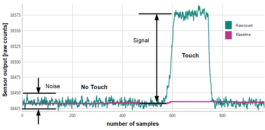
Test Method:
Power on the system and determine the peak-to-peak noise (N
pk_pk
) by calculating the difference between the maximum and minimum raw count values measured without a finger present.
Code snippet:
#define SNR_NUM_SAMPLES (100u) // Number of samples defined for noise measurement

typedef struct {
uint32_t noise[CY_CAPSENSE_SENSOR_COUNT];
} test_measurement_t;
test_measurement_t testReport;

uint32_t min_peak[CY_CAPSENSE_SENSOR_COUNT], max_peak[CY_CAPSENSE_SENSOR_COUNT];memset(min_peak, 0xFFFFFFFFU, sizeof(min_peak));
/* Measure noise */
for (int k = 0; k < SNR_NUM_SAMPLES; k++) {
Cy_CapSense_ScanAllSlots(&cy_capsense_context);
while (Cy_CapSense_IsBusy(&cy_capsense_context) == CY_CAPSENSE_BUSY) {
}
Cy_CapSense_ProcessAllWidgets(&cy_capsense_context);
for (int i = 0; i < CY_CAPSENSE_SENSOR_COUNT; i++) {
min_peak[i] =
cy_capsense_tuner.sensorContext[i].raw < min_peak[i] ?cy_capsense_tuner.sensorContext[i].raw :min_peak[i];
max_peak[i] =
cy_capsense_tuner.sensorContext[i].raw > max_peak[i] ?cy_capsense_tuner.sensorContext[i].raw :max_peak[i];
}
}
for (int i = 0; i < CY_CAPSENSE_SENSOR_COUNT; i++)
testReport.noise[i] = max_peak[i] - min_peak[i];Calculate the average of raw count samples taken without a finger present (Baseline)
Place a finger, of the minimum supported size, at the center of the sensor. Allow the reading to stabilize and then record the raw count with the touch
Calculate the average of raw counts with the finger touch (F
avg
)
Calculate the finger signal (Signal) as: Favg-Baseline
Calculate the Signal-to-Noise Ratio (SNR) as: Signal/Npk_pk
Verify if the measured SNR (SNR
measured
) is greater than the required SNR limit (SNR
limit
)
Note:
Typically, 500 samples are used for noise measurement during design , though this can be reduced in production testing due to time constraints. A minimum SNR of 5:1 is recommended.
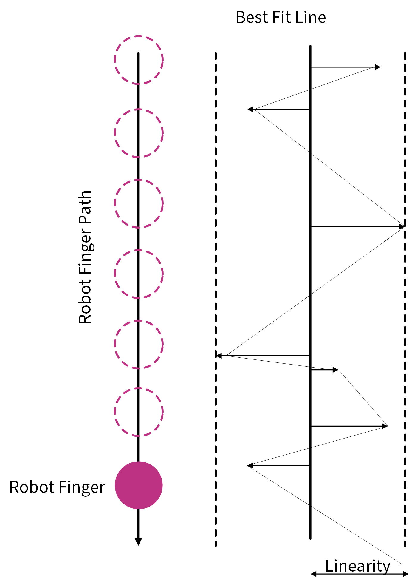
Linearity in cases of slider/touchpad
Linearity is defined as the minimum distance between the reported touch position and the best-fit line through all reported positions. To assess linearity for a slider/touchpad, follow the steps below:
Figure 2.
Deviation of position data
Measurement Procedure:
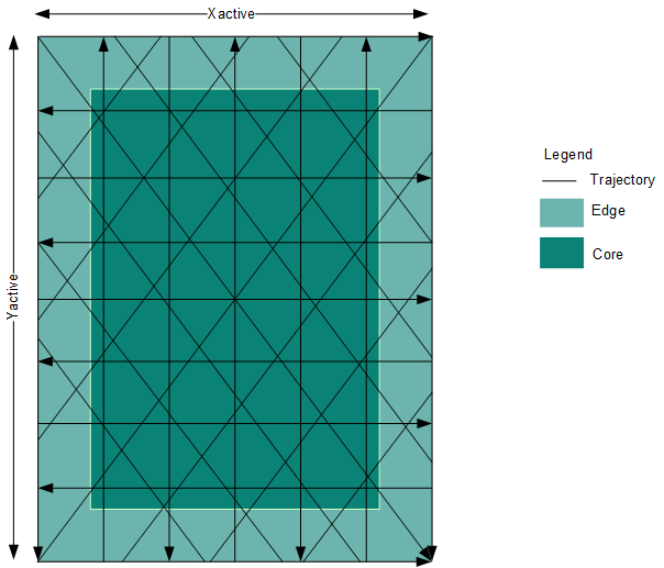
Drag the finger on the panel along the X-axis, Y-axis, and diagonals along the linear trajectories shown in Figure 3 below.
Figure 3.
Trajectories for 50 mm/s speed
Record the data from the CAPSENSE™ tuner
For each path of movement, determine the best-fit line through the recorded positions using a method such as linear regression (least squares). This line helps to determine the deviation between the data points and the model
Calculate the shortest distance of each reported coordinate (xi, yi) from the line equation using:
d(xi, yi) = |yi - mxi - b|/√(m² + 1)
Let us take a sample data set for better understanding and calculate shortest distances using the formula mentioned in point 4 :
Max resolution = 1086
Total DUT distance (X active or Y active)= 5 mm
Distance per pixel = (Total distance)/Max resolution = 5/1086 = 0.00483
Sample count | Position (in pixels) | Position (in mm) | Shortest distance |
|---|---|---|---|
497 | 110 | 0.506446 | 0.391626 |
498 | 110 | 0.506446 | 0.158181 |
499 | 121 | 0.55709 | -0.02602 |
500 | 142 | 0.653775 | -0.16545 |
501 | 192 | 0.883978 | -0.17505 |
502 | 254 | 1.169429 | -0.13094 |
503 | 298 | 1.372007 | -0.1674 |
504 | 343 | 1.57919 | -0.19939 |
505 | 376 | 1.731123 | -0.2851 |
506 | 490 | 2.255985 | -0.00818 |
507 | 548 | 2.52302 | 0.018029 |
508 | 592 | 2.725599 | -0.01844 |
509 | 637 | 2.932781 | -0.05042 |
510 | 754 | 3.471455 | 0.239922 |
511 | 809 | 3.724678 | 0.252703 |
512 | 853 | 3.927256 | 0.216238 |
513 | 898 | 4.134438 | 0.184251 |
514 | 937 | 4.313996 | 0.125402 |
515 | 986 | 4.539595 | 0.111322 |
516 | 1026 | 4.723757 | 0.05695 |
517 | 1031 | 4.746777 | -0.15411 |
518 | 1034 | 4.760589 | -0.37413 |
Figure 4.
Linearity graph plotted with sample data
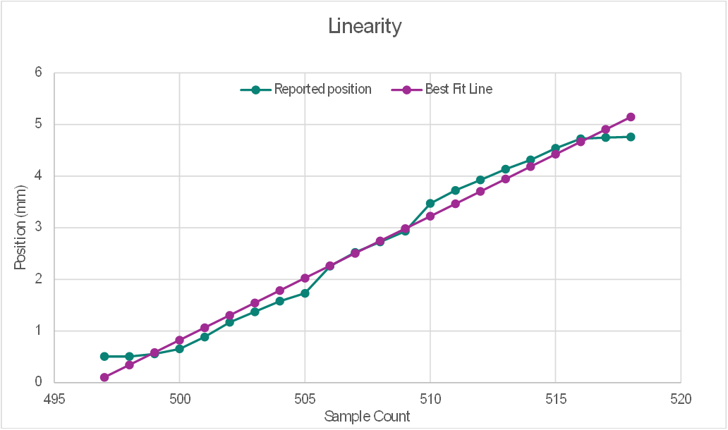
Linearity is considered to be good if the deviation between the measured output and the ideal output is small.
Usage example of BIST
The following code snippet shows a usage example of BIST:
Structure to store the data of widgets:
typedef struct {
uint32_t cp[CY_CAPSENSE_ELTD_COUNT];
uint32_t cm[CY_CAPSENSE_SENSOR_COUNT];
uint32_t csh[CY_CAPSENSE_TOTAL_CH_NUMBER];
uint16_t cmod1, cmod2, vdda;
uint8_t cRef[CY_CAPSENSE_TOTAL_WIDGET_COUNT];
uint8_t cComp[CY_CAPSENSE_SENSOR_COUNT];
uint32_t noise[CY_CAPSENSE_SENSOR_COUNT];
volatile cy_en_capsense_bist_status_t Raw_status, CRC_Status;
} test_measurement_t;
test_measurement_t testReport;
Perform various self-tests simultaneously using Cy_CapSense_RunSelfTest()
while (Cy_CapSense_RunSelfTest(
CY_CAPSENSE_BIST_RUN_AVAILABLE_SELF_TEST_MASK ,
&cy_capsense_context) != CY_CAPSENSE_BIST_SUCCESS_E) {}
Alternatively, perform specific tests using MASK or use low level APIs
while (Cy_CapSense_RunSelfTest(
 CY_CAPSENSE_BIST_ELTD_CAP_MASK |
CY_CAPSENSE_BIST_SNS_CAP_MASK |
CY_CAPSENSE_BIST_EXTERNAL_CAP_MASK |
CY_CAPSENSE_BIST_VDDA_MASK |
CY_CAPSENSE_BIST_SHIELD_CAP_MASK |
CY_CAPSENSE_BIST_SNS_INTEGRITY_MASK ,
 &cy_capsense_context) != CY_CAPSENSE_BIST_SUCCESS_E)
 { }
Stored values in cy_stc_capsense_widget_config_t structure
cy_capsense_context.ptrWdConfig->ptrEltdCapacitance // Electrode capacitance
cy_capsense_context.ptrWdConfig->ptrSnsCapacitance //Slot Sensor capacitance
cy_capsense_context.ptrBistContext->cMod01Cap //External Capacitance
cy_capsense_context.ptrBistContext->vddaVoltage //Vdda voltage
cy_capsense_context.ptrBistContext->ptrChShieldCap //Shield Electrode Capacitance
Note:
The above mentioned Code snippets are specifically for fifth-generation low-power CAPSENSE™. For other devices, MASK and stored location in structure may change.
Appendix
No | API name | testEnMask for "CapSense_RunSelfTest" API | Fifth -generation | Fifth-generation low-power |
|---|---|---|---|---|
1 | Cy_Capsense_CheckCRCWidget() | CY_CAPSENSE_BIST_CRC_WDGT_MASK | ✓ | ✓ |
2 | Cy_CapSense_CheckIntegritySensorRawcount() | Not available | ✓ | ✓ |
3 | Cy_CapSense_CheckIntegritySensorBaseline() | Not available | ✓ | ✓ |
4 | Cy_Capsense_MeasureCapacitanceSensorElectrode() | CY_CAPSENSE_BIST_ELTD_CAP_MASK | ✓ | ✓ |
5 | Cy_CapSense_MeasureCapacitanceSlotSensors() | CY_CAPSENSE_BIST_SNS_CAP_MASK | ✓ | ✓ |
6 | Cy_CapSense_MeasureCapacitanceShieldElectrode() | CY_CAPSENSE_BIST_SHIELD_CAP_MASK | ✓ | ✓ |
7 | Cy_CapSense_MeasureCapacitanceCap | CY_CAPSENSE_BIST_EXTERNAL_CAP_MASK | ✓ | |
8 | Cy_CapSense_MeasureVdda() | CY_CAPSENSE_BIST_VDDA_MASK | ✓ |
Note:
From the above list, only the most relevant tests for manufacturing are mentioned in this document. For more details on these functions, please refer to the CAPSENSE™ Middleware library.
References
Infineon Technologies AG:
001-85951: PSOC™ 4 and PSOC™ 6 MCU CAPSENSE™ design guide
;
Available online
CAPSENSE™ library and documents
;
Available online
Infineon Technologies AG:
001-79953: Getting started with PSOC™ 4 MCU
;
Available online
Revision history
Document version | Date of release | Description of changes |
|---|---|---|
** | 2025-04-04 | Initial release |
*A | 2025-04-10 | Updated the title and document number |
Trademarks
PSOC™, formerly known as PSoC™, is a trademark of Infineon Technologies. Any references to PSoC™ in this document or others shall be deemed to refer to PSOC™.