AN86233 PSOC™ 4 MCU low-power modes and power reduction techniques
About this document
Scope and purpose
AN86233 discusses how to use the PSOC™ 4 MCU low-power modes and features to operate at very low power levels while retaining essential functionality. Major topics include the five power modes, PSOC™ Creator power management functions, and other power-saving techniques and considerations. Three PSOC™ Creator example projects are included to demonstrate various aspects of low-power programming.
Note:
PSOC™ Creator supports all PSOC™ 4 devices, but ModusToolbox™ software supports PSOC™ 4S-series devices only. Supported devices are
4000S
,
4100S
,
4100S plus
,
4100S plus 256KB
,
4100S max
, and
4500s
.
Intended audience
This application note is for anyone who uses PSOC™ 4 MCU devices.
Introduction
PSOC™ 4 MCU low-power modes allow a reduction in overall power consumption while retaining essential functionality, especially when implemented with other power-saving features and techniques. This application note describes the device low-power modes, provides information on active mode power-saving methods, and discusses other low-power considerations.
The document assumes that you are familiar with developing applications using the ModusToolbox™ software environment or PSOC™ Creator. If you are new to PSOC™ 4 MCU, you can find an introduction in
AN79953 – Getting started with PSOC™ 4
MCU. If you are new to ModusToolbox™ software or PSOC™ Creator, see the
ModusToolbox™ software
or
PSOC™ Creator
home page. See
Related application notes
for more resources.
Power mode summary
PSOC™ 4 MCU features up to five power modes of operation. In order of power consumption and functionality, they are: active, sleep, deep sleep, hibernate, and stop.
Table 1
lists the typical current and wakeup times for each power mode. See the product line datasheet for other values and specific conditions.
Active mode is the normal operating mode in which all peripherals are available, and the CPU is executing instructions.
In Sleep mode, all peripherals except the CPU are available.
In Deep Sleep mode, the CPU, most peripherals, and the MHz clocks are disabled.
In Hibernate mode, no clocks are available, but logical states are retained.
In Stop mode, the CPU, clocks, and all peripherals are halted, and logical states are not retained, but GPIO states are retained or frozen.
Power mode | Current range (typical) (VDD = 3.3 V to 5.0 V ) | PSOC™ 4000/ 4000S/ 4100S/ 4100S plus/ 4100S plus 256k/ 4100S max | PSOC™ 4100 BLE | PSOC™ 4200 BLE | PSOC™ 4200DS | PSOC™ 4500S | PSOC™ 4700S | PSOC™ analog coprocessor | PSOC™ 4100PS | PSOC™ 4100/ 4200 | PSOC™ 4100M/ 4200M | PSOC™ 4200L |
|---|---|---|---|---|---|---|---|---|---|---|---|---|
Active | 1.3 mA to 14 mA | – | – | – | – | – | – | – | – | – | – | – |
Sleep | 1.0 mA to 3 mA | 0 | 0 | 0 | 0 | 0 | 0 | 0 | 0 | 0 | 0 | 0 |
Deep sleep | 1.3 µA to 15 µA | 35 µs | 25 µs | 25 µs | 35 µs | 35 µs | 35 µs | 35 µs | 35 µs | 25 µs | 25 µs | 25 µs |
Hibernate | 150 nA to 1 µA | Not applicable | 2 ms | 0.7 ms | Not applicable | 2 ms | 0.7 ms | 0.7 ms | ||||
Stop | 20 nA to 80 nA | Not applicable | 2 ms | 2.2 ms | 2 ms | 2 ms | 1.9 ms | |||||
The differences among the low-power modes are related to CPU and peripheral availability, wakeup and reset sources, power mode transition behaviors, and power consumption.
Table 2
shows the PSOC™ 4 MCU resources and their availability in different power modes.
Subsystem | Active | Sleep | Deep sleep | Hibernate | Stop |
|---|---|---|---|---|---|
CPU | ON | Retention 1 | Retention | OFF | OFF |
SRAM | ON | ON | Retention | Retention | OFF |
High-speed peripherals (SPI, UART, etc.) | ON | ON | Retention | OFF | OFF |
Universal digital blocks (UDBs) | ON | ON | Retention | OFF 3 | OFF |
VDAC | ON | ON | Retention 2 | OFF | OFF |
SPI slave and I 2 C slave (SCB-based) | ON | ON | ON | OFF | OFF |
High-speed clock (IMO, ECO, and PLLs) | ON | ON | OFF | OFF | OFF |
Low-speed clock (32 kHz) (ILO and WCO) | ON | ON | ON | OFF | OFF |
Brown-out detection | ON | ON | ON | ON | OFF |
Continuous time block (CTB) (opamp and comparators) | ON | ON | ON | OFF | OFF |
Continuous time block mini (CTBm) (opamp and comparators) | |||||
ADC | ON | ON | OFF | OFF | OFF |
Low-power comparators | ON | ON | ON | ON | OFF |
GPIO (output state) | ON | ON | ON | ON | Frozen 4 |
1
Retention: The configuration and state of the peripheral are retained. The peripheral resumes its operation when the device enters Active mode.
2
The state of VDAC, as well as any UDB-based function, is preserved by calling a
_Sleep()
function before entering deep sleep, and restored by calling a
_WakeUP()
function after exiting Deep Sleep mode.
3
When exiting Hibernate mode, all UDB-based functions are reinitialized because the PSOC™ 4 MCU device goes through a reset.
4
Frozen: The configuration, mode, and state of all GPIOs are locked. Changing the GPIO state is not possible until the device enters Active mode and the GPIOs are unlocked.
Low-power mode details
The ModusToolbox™ software environment currently supports PSOC™ 4 MCU devices that have Sleep and Deep Sleep power modes. PSOC™ Creator supports all PSOC™ 4 MCU devices, with all power modes. ModusToolbox™ software and PSOC™ Creator both have code examples that demonstrate these power modes; see
Power modes code example
.
shows the transitions between the power modes in PSOC™ MCU.
Table 3
lists the available wakeup sources for each mode.
Figure 1.
PSOC™ power mode transitions diagram
Note:
Blocks in grey are not available in the PSOC™ 4000, 4000S, 4100S, 4100S plus, 4100S plus 256k, 4100S max, 4200DS, 4500S, 4700S, 4100PS, and analog coprocessor product lines.
Sleep mode
In Sleep mode, the PSOC™ 4 Arm® Cortex®-M0/M0+ CPU does not run instructions; instead, it waits for an interrupt to occur. The SRAM is retained but not written to or read by the CPU. It can be accessed by DMA in those parts that support DMA. All other peripherals and clocks continue to run.
Sleep mode wakeup sources
Any interrupt source in the device can wake the device from Sleep mode. All peripherals can remain active and generate interrupts.
Sleep mode transitions
ModusToolbox™ and PSOC™ Creator supply API functions to enter sleep. These functions configure the device for sleep. No other API calls are necessary.
ModusToolbox™ software: Cy_SysPm_CPU_EnterSleep()
– Sets the system into Deep Sleep power mode and calls the registered callback functions. This is a CPU-centric power mode. It means that the CPU has indicated that it is in sleep mode and its main clock can be removed.
Returns the current sleep status
.
PSOC™ Creator
:
CySysPmSleep()
– Sets the system into s power mode and calls the registered callback functions. This is a CPU-centric power mode. It means that the CPU has indicated that it is in sleep mode and its main clock can be removed.
No return value
.
Exit from Sleep mode occurs when an interrupt is triggered. Upon exiting Sleep mode, the device re-enters Active mode. The configuration of sleep wakeup sources requires only that their interrupts be enabled.
Sleep mode use cases
Sleep mode should be used when peripherals such as the ADC, CAPSENSE™, digital communication, or others must remain active, but CPU activity is not required. This can reduce current consumption between events such as ADC conversions and digital communication transactions.
Deep Sleep mode
In Deep Sleep mode, the high-frequency clocks and peripherals that require high-frequency clocks are disabled. The high-frequency clocks include the internal main oscillator (IMO), external crystal oscillator (ECO), and phase-locked loops (PLLs). Note that the ECO and PLLs are not available in all PSOC™ 4 MCU devices.
The internal low-speed oscillator (ILO) clock remains active and can be used to clock the watchdog timer (WDT), which can be used as a sleep timer to wake the system from deep sleep. Some PSOC™ 4 MCU devices also include a watch crystal oscillator (WCO) that can operate during deep sleep.
The I
2
C block can continue operating in Slave mode to monitor the I
2
C bus, allowing wakeup upon I
2
C address match.
Deep Sleep mode wakeup sources
An I
2
C address match, the WDT, GPIO interrupts, CTB/CTBm comparator interrupts, and low-power comparator interrupts can wake the device from deep sleep. The WDT block contains multiple counters that can be configured independently to generate interrupts, resets, or both. This allows the WDT to function as a sleep timer as well.
Deep Sleep mode transitions
ModusToolbox™ software and PSOC™ Creator supply API functions to enter Deep Sleep. These functions configure the device for Deep Sleep. No other API calls are necessary.
ModusToolbox™ software: Cy_SysPm_CpuEnterDeepSleep()
– Sets the system into Deep Sleep power mode. If firmware attempts to enter this mode before the system is ready, the device will go into Sleep mode instead and automatically enter the originally intended mode when the hold-off expires.
Returns the current sleep status
.
PSOC™ Creator: CySysPmDeepSleep()
– Sets the system into Deep Sleep power mode. If firmware attempts to enter this mode before the system is ready, then the device will go into Sleep mode instead and automatically enter the originally intended mode when the hold-off expires.
No return value
.
Exit from Deep Sleep mode occurs when an interrupt is triggered. Upon exiting DeepSleep, PSOC™ 4 re-enters Active mode. The configuration of Deep sleep wakeup sources requires only that their interrupts be enabled.
Peripheral deep sleep configuration
When a device goes into deep sleep some peripherals need to be configured so that they can continue to operate in deep sleep or wake the device from deep sleep.
ModusToolbox™
software:
To ensure that a peripheral is configured correctly for deep sleep, ModusToolbox™ has specific API functions
_DeepSleepCallback()
and
_DeepSleep()
. These configure the peripheral for operation in deep sleep and waking up from deep sleep. See the
peripheral driver library (PDL)
for more information.
PSOC™ Creator:
Components can be configured to operate in deep sleep to save power, save their current state, or both. In these cases, use the component’s specific API function
_Sleep()
to store the current component state before calling
CySysPmDeepSleep();
and
_WakeUp()
after waking up from deep sleep. Depending on your application, it may be faster to simply call the component’s
_Stop()
function before entering Deep Sleep mode and
_Start()
after waking.
Deep sleep mode use cases
The Deep Sleep mode should be used when the PSOC™ 4 high-performance analog and digital peripherals are not needed, but the device still needs to be able to wake up periodically using the WDT, or upon other events such as an I
2
C address match.
Regular wakeup intervals enable periodic use of Active mode peripherals, such as the ADC, to take readings or scan CAPSENSE™ button inputs.
Hibernate mode with PSOC Creator
In Hibernate mode, all clocks and synchronous peripherals in PSOC™ 4 MCU are disabled. The pins and low-power comparators may remain active, and the SRAM and UDB register states are retained.
Currently ModusToolbox™ software does not support any PSOC™ 4 MCU device that supports Hibernate mode.
Note:
The PSOC™ 4000, 4000S, 4100S, 4100S plus, 4100S plus 256k, 4100S max, 4200DS, 4500S, 4700S, 4100PS and analog coprocessor product lines do not support Hibernate mode.
Hibernate mode wakeup sources
Pin and low-power comparator interrupts can wake the device from Hibernate mode. Any wakeup from Hibernate mode causes a device reset, but SRAM and some register states are retained, allowing the wakeup reset reason to be detected.
Although SRAM is retained, after reset, the C startup code initializes all global and static variables to either an initial value or zero. To prevent a variable from getting reinitialized after waking from hibernate, use the
CY_NOINIT
attribute in the definition of the variable.
To make sure a variable does get initialized, your code should determine if the reset was not caused by a wakeup from Hibernate mode. After the return to Active mode from a reset, call the
CySysPmGetResetReason()
API function to determine if the reset was a wakeup from hibernate, or from some other reset condition. The following code shows how to define a non-initialized variable, and initialize it if the reset was not due to a hibernate wakeup.
/* Define non-initialized global variable */
int32 CY_NOINIT testVarNoInit;

/* Inside of main()   */
/* Initialize variable when PSoC™ is not reset from hibernation wakeup */
if( CySysPmGetResetReason() != CY_PM_RESET_REASON_WAKEUP_HIB )
{
    testVarNoInit = 0;
}
Hibernate mode transitions
Enter Hibernate mode using the
CySysPmHibernate()
API function. This function configures the device for Hibernate mode. No other function calls are necessary because all components including clocks are powered down and will be reinitialized when exiting Hibernate mode with a reset. The only exception is that the low-power comparator may remain active to cause a wakeup from Hibernate mode.
Exit from Hibernate mode occurs when a pin or low-power comparator interrupt is triggered. Upon exiting Hibernate mode, PSOC™ MCU resets. After the return to Active mode from a reset, you can call
CySysPmGetResetReason()
to detect the Hibernate wakeup reset. The specific pin or comparator interrupt can then be detected using the component APIs, as those register states are retained.
Although not required, you have the option to lock the state of all I/O cells (GPIOs) by calling
CySysPmfreezeIo()
before entering Hibernate mode. The
CySysPmUnfreezeIo()
function should be called after a wakeup from Hibernate mode before the pins can again change state. Using these functions prevents unexpected GPIO transitions during and after reset.
Hibernate mode use cases
Hibernate mode should be used when periodic wakeup is not required, and the device must use less than 1 µA current. It may also be useful for a wakeup on an analog or digital signal transition, while requiring minimal current.
Note that Hibernate mode can be used effectively if your code is organized as a state machine, and the CPU can start executing the code from the previously known state before wakeup once the device wakes up from Hibernate mode. You must use the
CY_NOINIT
attribute in the definition of the state variables to make sure that the state variables are not reinitialized after wakeup from Hibernate mode. You can call
CySysPmGetResetReason()
to detect the hibernate wakeup reset, as mentioned in the previous section.
Stop mode with PSOC Creator
Stop mode offers the lowest possible current consumption without removing power from the PSOC™ 4 MCU supply pins. All peripherals are disabled, and the SRAM and register states are
not
retained. The device pins may be “frozen” and retain their drive modes and logical states. A dedicated wakeup pin, P0[7], is available to wake the device from Stop mode.
Currently, ModusToolbox™ software does not support any PSOC™ 4 MCU device that supports Stop mode.
Note:
The PSOC™ 4000, 4000S, 4100S, 4100S plus, 4100S plus 256k, 4100S max, 4200DS, 4500S, 4700S, 4100PS and analog coprocessor product lines do not support Stop mode.
Stop mode wakeup sources
The dedicated wakeup pin P0[7] is the only wakeup source available in Stop mode. You can set its input wakeup polarity to rising or falling edge by calling the
CySysPmSetWakeupPolarity()
function.
Stop mode transitions
To enter Stop mode, call
CySysPmStop()
. This function configures the device for Stop mode, including freezing the I/O states. If you use the dedicated wakeup pin, set its input wakeup polarity before entering Stop mode with the
CySysPmSetWakeupPolarity()
function.
Exit from Stop mode occurs when the dedicated pin wakeup is triggered, the reset signal goes LOW, or if power is cycled. Upon exiting Stop mode, PSOC™ 4 MCU resets. Upon return to Active mode after reset, you can call
CySysPmGetResetReason()
to determine whether Stop mode was exited by toggling the wakeup pin or a power cycle. After a wakeup pin reset, the GPIO states remain frozen and must be unfrozen using the
CySysPmUnfreezeIo()
function before the pin states can be changed. There is no need to call
CySysPmfreezeIo()
before entering Stop mode because
CySysPmStop()
freezes I/O cells implicitly.
Stop mode use cases
Use Stop mode when the absolute minimum power consumption and functionality are required. It is most useful in applications where a host controller or a user input such as a button press can trigger the dedicated wakeup pin, and the power supply topology does not allow disconnecting power from the device.
For more information on the power mode transition APIs, see the
system reference guide
.
Power mode wakeup summary
All power modes exit upon two conditions: power cycling or driving the reset input LOW. All states are lost in either case for
all
power modes.
Table 3
provides a summary of the events and hardware that can be used to exit the current low-power mode and return to Active mode.
Low-power mode | Wakeup source | Wakeup action |
|---|---|---|
Sleep | Any interrupt source | Interrupt |
Any reset source | Device reset | |
Deep sleep | GPIO interrupt | Interrupt |
Low-power comparator | Interrupt | |
CTB/CTBm comparator | Interrupt | |
SCB (I 2 C address match) | Interrupt | |
WDT 5 | Interrupt or device reset | |
XRES (external reset pin) | Device reset | |
Hibernate | GPIO interrupt | Device reset |
Low-power comparator | Device reset | |
XRES (external reset pin) 6 | Device reset | |
Stop 7 | WAKEUP pin (P0[7]) | Device reset |
XRES (external reset pin) 6 | Device reset |
5
The WDT can be configured to generate both interrupts and resets at different intervals. See the technical reference manual (TRM) for the applicable PSOC™ 4 MCU device family.
6
XRES triggers a full system reset. All states including frozen I/Os are lost. In this case, the cause of wakeup is not detectable after the device restarts.
7
ModusToolbox™ software environment does not support Hibernate or Stop modes.
Power reduction techniques
In many applications, you can gain additional power reductions by properly managing PSOC™ 4 MCU blocks as well as powering down external components. This section presents some techniques for doing so.
Turn OFF peripherals in ModusToolbox software
You can save unnecessary current consumption by disabling unused blocks. The power saved depends on the block disabled.
Any block that can be disabled in Active or Sleep mode is supported by
_Enable()
and
_Disable()
functions. The
_Disable()
function immediately halts all operations of the peripheral. The peripheral may be actively performing a task, so check its status before disabling it. The following code snippet uses the timer/counter from the TCPWM block as an example.
/* <Check task status here.> */

/* Disable the peripheral. */
Cy_TCPWM_Counter_Disable(TCPWM, MY_TCPWM_CNT_NUM);
Restart the peripheral by calling the _Enable() function. It is recommended that the peripheral be re-initialized before enabling.
/* Initialize the peripheral */
Cy_TCPWM_Counter_Init(TCPWM, MY_TCPWM_CNT_NUM, &config);

/* Enable the peripheral. */
Cy_TCPWM_Counter_Enable(TCPWM, MY_TCPWM_CNT_NUM);
Some peripherals such as the TCPWM may need to be trigger started. This is a software trigger that ensures that all TCPWM counters are started at the same time. Call this function when the when one or more TCPWM counters need to be started.
/* Trigger start the peripheral. */
Cy_TCPWM_TriggerStart(TCPWM, MY_TCPWM_CNT_MASK);
Note:
Not all peripherals need to be trigger started, check the
peripheral driver library(PDL)
for more information.
Turn OFF components in PSOC Creator
The easiest way to reduce power in Active mode is to turn OFF unused PSOC™ Creator components.
Any component that can be disabled in Active or Sleep mode includes a
_Stop()
function in its API. This function immediately halts all operation of the component and sets it to its lowest power state. The component may be actively performing a task, so check its status before stopping it.
/* <Check task status here.> */

/* Stop the Component. */
MyComponent_Stop();
Restart a component by calling its start function:
/* Start the Component. */
MyComponent_Start();
Any component that must preserve its configuration data before powering down includes a _Sleep() function in its API. The
_Sleep()
function saves all necessary component settings and then calls the
_Stop()
function. In some cases, the
_Sleep()
function does nothing but call
_Stop()
.
/* < Check task status here.> */

/* Sleep the Component. */
MyComponent_Sleep();
When a component is put to sleep, it should be awakened by calling its
_Wakeup()
function. This restores the component to its pre-sleep state. The
_Start()
function also brings the component back into operation, but it is reinitialized to its default state.
/* Wake the Component. */
MyComponent_Wakeup();
_Sleep()
and
_Stop()
both result in the same amount of power savings. The difference lies in whether the component needs to resume from exactly where it left off.
Run components at a lower speed
Clocked integrated circuits consume more current as their clock rates increase. This is because parasitic and designed capacitances are charged and discharged more rapidly, requiring more current. Reducing the operating frequency of PSOC™ MCU components can greatly reduce the current consumption. This technique can be applied to the CM0/CM0+ CPU, SAR ADC, digital components, and others.
Reduce supply voltage
Reducing the supply voltage is probably the easiest thing you can do to reduce the overall power consumption. Even if the current stays the same, reducing the supply voltage from 5 V to 3 V reduces power consumption by 40 percent! Although the PSOC™ MCU device can operate below 1.8 V, you still need to consider the voltage requirements of other devices in the system.
Use PSOC 4 MCU device to gate current paths
Your PCB may contain other components that draw power; the PSOC™ 4 MCU device can be used to control the current consumed by them. Note that the maximum pin source and sink capabilities listed in the datasheet must not be exceeded. The following example is shown using a PSOC™ Creator component, the same theory applies to ModusToolbox™ software.
A good example of this scenario is a thermistor application, as
Figure 2
shows. In this case, the PSOC™ 4 MCU device measures the temperature using the voltage on an analog pin, which changes as the thermistor resistance changes.
Figure 2.
Typical thermistor application
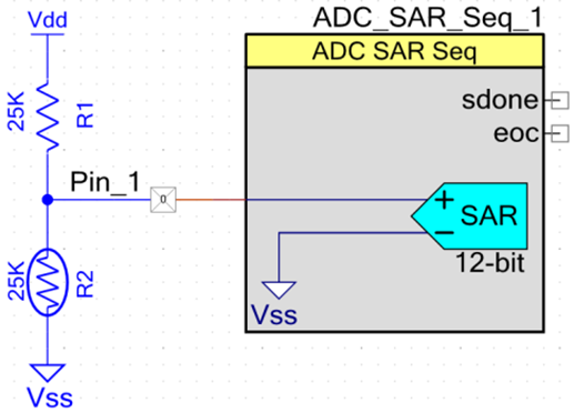
The ADC can be turned OFF when not in use, but external components still consume power because the current path through the resistor and thermistor remains. A simple solution with PSOC™ 4 MCU is to use a second pin as a switch to ground, as
Figure 3
shows.
Figure 3.
Using a GPIO as a ground switch
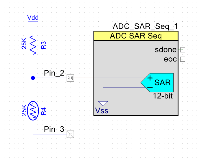
In this configuration, the current flow can be stopped by writing a ‘1’ to Pin_3, allowing the pin to float. This removes the current consumption by reducing the voltage differential across the two resistors to 0 V. Writing a ‘0’ resumes the current flow. The resource use of this power-saving feature is only one pin and a few lines of code.
Alternatively, when the measurement is not required, Pin_3 drive mode can be changed to High-Z analog so that there is no path for the current to flow. For the measurement, Pin_3 drive mode should be set to strong and logic 0 should be written at the pin.
Use DMA to move data
You can save power any time you offload a task from the CPU and either halt the CPU or let it do something else in parallel. The DMA engine can be used in both Active and Sleep modes to transfer data with no CPU use. The power saved is either the difference between CPU active and CPU Stop power modes if the CPU can be halted, or lower CPU active current if the CPU can be clocked at a slower frequency and still get the same work done.
The following devices support DMA: 4000DS, 4100 BLE, 4100M, 4100PS, 4100S plus, 4100S max, 4200 BLE, 4200DS, 4200L, 4200M, 4100S pus 256k, 4500S, and analog coprocessor.
Other low-power mode considerations
This section presents tips, tricks, and recommendations related to the use of PSOC™ low-power modes.
Clocks
In some cases, running the clocks faster can result in a lower average current consumption. For example, consider a PSOC™ MCU design that takes a reading from a sensor once every second, performs several calculations, and then transmits the results to another device.
You can use Sleep or Deep Sleep mode to reduce the power when the PSOC™ MCU device is idle, but the average current consumption is higher because of the time spent in Active mode.
Figure 4
is a representation of the current consumption of this example with the system clocks set at 3 MHz.
Figure 4.
Example current profile with 3-MHz clock
Depending on the tasks or calculations that are being performed when the PSOC™ 4 MCU device is awake, it may be possible to complete them sooner by running the system clocks faster. This can reduce the average current consumption because the PSOC™ 4 MCU device is in Active mode for less time.
Figure 5
is a representation of Active mode timing, broken up into tasks.
Figure 5.
Analysis of tasks in Active mode at 3 MHz
The time required for some tasks does not change even if the system clock frequency increases. Sensor reading and data transmitting fall into this category. Other tasks, however, require less time if the CPU operates at a faster frequency.
At some point, the benefit of a shorter active time is overcome by the energy required to drive the clocks at a higher rate. Assume that the optimal speed is 12 MHz, as
Figure 6
shows. With a 12 MHz clock, the time spent in Active mode is about half as long as with a 3 MHz clock.
Figure 7
shows that the peak current consumption is greater when the clocks are faster, but the overall average is lower.
Figure 6.
Analysis of tasks in Active mode at 12 MHz
Figure 7.
Example current profile with a 12-MHz clock
You may also be able to reduce the peak active current by applying other suggestions in this application note.
Project 3: Deep sleep ADC
is an example project that wakes once a second, takes a temperature reading with the ADC, transmits the data via a UART, and then goes back to deep sleep.
WDT
The WDT can operate in Active, Sleep, and Deep Sleep modes. The counters in the WDT can generate interrupts or resets, depending on the configuration and operating conditions. This allows the WDT to replace a traditional sleep timer in addition to guaranteeing reliable operation.
Increasing the WDT interval or disabling it entirely before entering low-power modes can reduce the time spent in Active mode and the overall power consumption. The WDT is not active in Hibernate or Sop modes.
More information on the operation of the WDT and the associated API is available in the
PSOC™ TRM
,
peripheral driver library (PDL)
, and the
PSOC™ Creator system reference guide
.
PIOs
GPIOs can continue to drive the external circuitry when the PSOC™ device is in a low-power mode. This is helpful when you need to hold external logic at a fixed level, but it can lead to wasted power if the pins needlessly source or sink current. The specific power savings of this technique depend on the circuit attached to the specific GPIO pin.
You should analyze your design and determine the best state for your GPIOs during low-power operation. If holding a digital output pin at logic 1 or 0 is best, then use the GPIO or Pin
_Write()
function to set it.
ModusToolbox™
software:
/* Set MyPin to ‘0’ for low power. */
Cy_GPIO_Write(MYPIN_0_PORT, MYPIN_0_NUM, 0u);
Configure all unused GPIOs to analog High-Z unless there is a specific reason to use a different drive mode. A port-wide drive mode may be set using the
_SetDriveMode()
function.
/* Set MyPin to Alg HI-Z for low power. */
Cy_GPIO_SetDriveMode(MYPIN_0_PORT, MYPIN_0_NUM, CY_GPIO_DM_HIGHZ);
PSOC™
Creator:
/* Set MyPin to ‘0’ for low power. */
MyPin_Write(0);
Configure all unused GPIOs to analog High-Z unless there is a specific reason to use a different drive mode. A port-wide drive mode may be set using the
_SetDriveMode()
function.
/* Set MyPin to Alg HI-Z for low power. */
MyPin_SetDriveMode(MyPin_DM_ALG_HIZ);
PSOC™ 4 MCU’s flexibility makes it easy to manage GPIO drive modes to prevent unwanted current leakage. See
AN86439 – PSOC™ 4 – Using GPIO pins
for more information on the GPIO pin configurations.
TCPWM
When using a counter, timer or PWM, you should configure the clock sourcing the channel as to have as low a frequency as possible while still meeting your frequency and accuracy requirements. For example, if you need to generate a 1-second interrupt with a timer, it is better to use a clock frequency of 1 kHz with the period equaling 1,000 counts than a clock frequency of 1 MHz with a period equal to 1,000,000 counts. The power savings from reducing the TCPWM clock is mostly linear based on clock frequency.
Figure 8
shows a comparison between the clock settings for the TCPWM block.
Figure 8.
TCPWM clock settings comparison
The TCPWM block has a clock prescaler feature. For minimum power consumption, maximize the peripheral clock divider Clk_Peri before using the TCPWM clock prescaler.
SAR ADC
If the full-rated accuracy of ADC results is not required, use a lower resolution and do not use averaging, which reduces the number of ADC clocks required for the same sample rate.
If the maximum sample rate is not required, consider using the single-shot mode instead of continuous mode. This avoids the SAR ADC operating all the time. In single shot mode, the ADC samples only when triggered by software or hardware.
Deep sleep and hibernate regulators
PSOC™ 4 MCU has two low-power regulators that are used to maintain logic states in deep sleep and hibernate:
The deep sleep regulator supplies the circuits that remain powered in Deep Sleep mode, such as the ILO and SCB. The deep sleep regulator is available in all power modes except the Hibernate mode. In active and sleep power modes, the main output of this regulator is connected to the output of the active digital regulator (VCCD). This regulator also has a separate replica output that provides a stable voltage for the ILO. This output is not connected to VCCD in Active and Sleep modes.
The hibernate regulator supplies the circuits that remain powered in Hibernate mode, such as the sleep controller, low-power comparator, and SRAM. The hibernate regulator is available in all power modes. In Active and Sleep modes, the output of this regulator is connected to the output of the digital regulator. In Deep Sleep mode, the output of this regulator is connected to the output of the deep sleep regulator.
Neither of these regulators powers the V
CCD
supply. Each regulator powers an internal power supply domain and is not brought out on a pin of the device.
Note:
The hibernate regulator is not available in PSOC™ 4000, 4000S, 4100S, 4100S plus, 4100S Plus 256k, 4100S max, 4200DS, 4500S, 4700S, 4100PS, and analog coprocessor product lines. These devices do not support Hibernate mode.
Debug interface
PSOC™ 4 MCU supports on-chip debugging. You may observe a higher current consumption than expected while in debug mode. This is normal because the programming and debug interface remains active in all low-power modes.
Power measurements may also be skewed if the debug pins are set to SWD mode and a MiniProg3 programmer/ debugger is attached, even if the PSOC™ 4 MCU device is not in debug mode.
PSOC Creator
Debug interface pins are set to GPIO mode on all chips from the factory, but a new PSOC™ Creator project sets them to SWD mode by default. The registers that control the debug interface can be changed only at programming time. Use the System tab in the
.cydwr
file of the PSOC™ Creator project to set the pins to GPIO mode, as
Figure 9
shows.
Figure 9.
Disable debug interface to reduce power

ModusToolbox software
Debug interface pins are set to GPIO mode on all chips from the factory, but a new ModusToolbox™ project sets them to SWD mode by default.
Do the following to change the debug interface pins to GPIO mode:
Go to .
In the device configurator, go to Pins and look for the pins labeled “CYBSP_SWDIO” and “CYBSP_SWDCK”, as Figure 10 shows.
Deselect these pins to set the device in GPIO mode.
Figure 10.
Change device mode to GPIO

When the debug interface is disabled by setting these pins to GPIO mode, a reset must occur to access the debug controller inside the PSOC™ MCU device. This means that the only thing you cannot do is attach the debugger to a running project. If the pins are in SWD mode, either of the following things should be done before entering a low-power mode to achieve minimum power: pull the pins up or down using external components or change the pin mode to High-Z.
It is recommended that you set the debug interface pins to GPIO mode for any released product. For more information about programming and debugging, see the device datasheets and TRMs.
Code examples
The following projects were designed to show the different aspects of low power modes in both ModusToolbox™ software and PSOC™ Creator.
ModusToolbox software code examples
The ModusToolbox™ software environment supports two projects: mtb-example-psoc4-power-modes and
mtb-example-psoc4-deep-sleep-adc
. These projects support all devices supported in ModusToolbox™ software (currently, 4000S, 4100S, 4100S plus, 4100S plus 256k, and 4500S).
To open these projects in ModusToolbox™ software select
New application
in the ModusToolbox™ software
quick panel
. A list of board support packages (BSP) are available to choose from. The BSP corresponds to the specific device that is being used. When a BSP is selected, a list of code examples that correspond with that BSP can be chosen, either mtb-example-psoc4-power-modes and mtb-example-psoc4-deep-sleep-adc can then be selected.
PSOC Creator projects
Three projects are included with this application note for all PSOC™ 4 MCU devices, and one project for PSOC™ 4100PS, to demonstrate several of the concepts discussed in this application note. All the source code for each example is included in its
main.c
file and is heavily commented. It is recommended that you take the time to walk through each example’s source code to learn the basic operation.
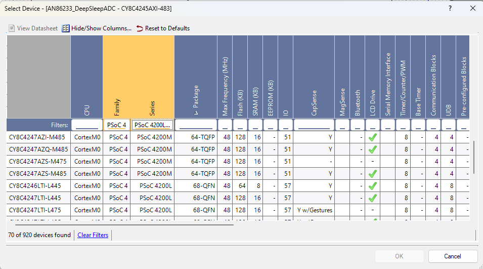
The default target device set for the PSOC™ Creator projects is the CY8C4245AXI-483 device, which is used in CY8CKIT-042 and CY8CKIT-049 kits. The projects can be easily adapted to kits that use other PSOC™ 4 MCU devices. You may need to change the pins connecting to external components and device selection. Review the specific kit documentation for connections and device type.
Do the following to configure the projects for another PSOC™ 4 MCU device:
PSOC 4 MCU code examples
Power modes code example
ModusToolbox™
software:
This code example is located on GitHub at mtb-example-psoc4-power-modes; you can easily compare all Sleep and Deep Sleep modes with Active mode.
To change the power mode the device is in, press the on-board button longer than two seconds to put the device into Deep Sleep. To switch the device into Sleep mode, press the button between 200 ms and two seconds. This allows the device to easily switch power modes so that they can be compared. See
Figure 13
to see how to switch modes.
Figure 13.
Switch power modes
You can measure the current in PSOC™ 4 development kits; see the kit guide for more information.
PSOC™ Creator:
The project (AN86233_Power Modes) is available in the zip file associated with this application note. With this project, you can easily compare all four low-power modes with Active mode. You can edit the code in one place to set the
PM_TO_DEMO
constant to the desired power mode constant. The following code snippet shows an example of the code in which the Deep Sleep mode is selected.
/* Power Modes Constants */
#define PM_SLEEP         1u
#define PM_DEEP_SLEEP    2u
#define PM_HIBERNATE     3u
#define PM_STOP          4u

/* Set PM_TO_DEMO to power mode */
#define PM_TO_DEMO  PM_DEEP_SLEEP
After this selection is made, build the project and program the device. The project starts in Active mode until the switch on the development board is pressed. The LED flashes quickly according to the number of times assigned to the power mode constant. In this example, the LED flashes twice for deep sleep.
The project stays in the low-power mode until the switch is pressed again. It then flashes slowly the same number of times to let you know that the project is back in Active mode. Using an ammeter, you can measure the current in each mode. To evaluate a different power mode, set
PM_TO_DEMO
to a different power mode constant, rebuild the project, and reprogram the PSOC™ 4 MCU device.
Note:
A separate project (AN86233_PSoC_4100PS) is available for devices without Hibernate and Stop modes; it is available in the zip file. The devices that do not support hibernate or stop modes are PSOC™ 4000, 4000S, 4100S, 4100S plus, 4100S plus 256k, 4100S max, 4200DS, 4500S, 4700S, 4100PS, and analog coprocessor product lines.
Project 2: Low power comp
The PSOC™ Creator project (AN86233_LPComp) is available in the zip file associated with this application note.
This project demonstrates how the low-power comparator (LPComp) can be used to wake the PSOC™ 4 MCU device from hibernate and return to Active mode. Two 1-MΩ external resistors and a potentiometer, or a voltage source must be added to the development kit to complete the project. The two resistors form a voltage divider to provide a reference voltage that is one-half of V
DDD
.
The potentiometer simulates an external changing voltage that triggers an exit from hibernate back to Active mode by causing an interrupt. An interrupt occurs when the potentiometer voltage makes a transition from higher than the reference to lower than the reference, or vice versa.
After a reset, the project is in Active mode. The LED is lit anytime the project is in Active mode and turned OFF in hibernate. Pressing the kit button puts the PSOC™ 4 MCU device in Hibernate mode until LPComp senses that the input voltage is changing from above to below the reference voltage (V
DDD
/2 in this case), or vice versa.
You can change the code so that instead of going into hibernate when the kit button is pressed, the device goes into sleep or deep sleep. The operation should be identical, but the power consumption differs among low-power modes.
Note:
Currently, this project is supported only in PSOC™ Creator.
Project 3: Deep sleep ADC
This project works for both ModusToolbox™ software and PSOC™ Creator.
ModusToolbox™
software:
The code example is located on GitHub at mtb-example-psoc4-deep-sleep-adc.
PSOC™ Creator:
The project (AN86233_DeepSleepADC) is available in the zip file associated with this application note.
This project is an example of how to periodically wake up, take a reading with the SAR ADC, do a transform on the data, send the data out the serial port (UART), and switch back to Deep Sleep mode. It performs this sequence about once a second but remains in deep sleep 99.9 percent of the time between samples to reduce power by almost three orders of magnitude.
The project uses the ILO and a WDT (WDT0) to wake from deep sleep once a second. The ILO is a low-power oscillator but is not very accurate, with a specification of 32 kHz –50 percent to +100 percent. The IMO, on the other hand, is much more accurate at ±2 percent, but it requires more power and does not operate during Deep Sleep. It always operates when the PSOC™ 4 MCU device is in Active mode. You can use the IMO to calibrate the ILO with the System ILO functions.
The ILO Trim is used to adjust the WDT0 counter period so that it is within ±10 percent. The large drift of the ILO is mainly a function of the voltage and temperature, so you do not have to adjust the trim that often. In the example, it is trimmed every 60th time the component wakes from deep sleep or once a minute. You can change that from a fixed 60-second update to whenever the measured die temperature or supply voltage changes by more than a set value. See
Figure 14
for the program flow of the example project.
Note:
The WDT interrupt vector number must be updated in the project depending on the target device, using the WDT_IRQN macro in the main.c file. To know the vector number (IRQx), see the “Interrupts” chapter of the architecture reference manual of the target device.
Figure 14.
AN86233_DeepSleepADC program flow
Average power
To determine the average power of this example, you need to measure both the time and current in each mode, assuming that the duty cycle between power modes is consistent. This period of the firmware is about 1 second. So, if you add up the time that the PSOC™ 4 MCU device stays in active and deep sleep modes in one period, it would be about 1 second.
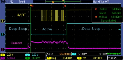
First, measure the current consumption and the time that the device stays in Active mode.
Figure 15
shows that the duration in Active mode is about 630 µs, and it consumes about 5000 µA (5.0 mA) during that time. You can also see the UART communication in
Figure 15
and notice that the PSOC™ 4 MCU device does not return to deep sleep until the UART has completed its transmission. The duration of the LED drive (active LOW) signal, along with the current measurement, is used to determine whether the device is in Active mode versus Deep Sleep mode. In Deep Sleep mode, the current is about 3.5 µA, and the signal duration is about 999.4 ms.
Figure 15.
Measuring project Active mode parameters
If you average the power for both Active and Deep Sleep modes, as shown in
Table 4
, it is easy to see that using the deep sleep low-power mode reduced the 5-mA current from Active mode to an average of 6.7 µA, almost by three orders of magnitude!
Deep sleep | Active | Total | Unit | |
|---|---|---|---|---|
Time (ms) | 999.4 | 0.63 | 1000 | ms |
Current (µA) | 3.5 | 5000 | µA | |
Time × I | 3498 | 3150 | 6648 | ms × µA |
Average current | 6.7 | µA | ||
To put all this into perspective, if this project were running on a 300-mAh battery without using the low-power mode, the battery life would be about 60 hours (300 mAh / 5 mA). With power mode cycling, the same 300-mAh battery would last almost 44,800 hours, or over 5 years!
Of course, the duty cycle time in both Active and Deep Sleep modes greatly affects the average power, but so does the power consumed in each of those modes. Cycling between two power modes does add some complexity to the design, but for battery-powered applications, it may be well worth it.
ModusToolbox hardware configuration
For ModusToolbox™ hardware configuration see the code example readme. The ModusToolbox™ code example readmes shows how to set up and configure all hardware.
PSOC Creator hardware configuration
Infineon provides different development kits for the PSOC™ MCU families, including CY8CKIT-042 for PSOC™ 4200, CY8CKIT-044 for PSOC™ 4200M, and CY8CKIT-046 for PSOC™ 4200L MCUs. Also available are low-cost kits with a small form factor (prototyping kits), such as CY8CKIT-049 for PSOC™ 4200, CY8CKIT-043 for PSOC™ 4200M, and CY8CKIT-147 for PSOC™ 4100PS MCUs.
These kits offer different features, but all include a user button and LED connected to the PSOC™ 4 MCU device. You must make the appropriate pin assignments for each kit for the projects to function properly.
Table 5
provides the pin mapping across the PSOC™ pioneer kits;
Table 6
provides the pin mapping across the PSOC™ 4 MCU prototyping kits.
Function | CY8CKIT-042 (PSOC™ 4200) | CY8CKIT-044 (PSOC™ 4200M) | CY8CKIT-046 (PSOC™ 4200L) |
|---|---|---|---|
Red LED (active LOW) | P1[6] | P0[6] | P5[2] |
Switch (active LOW) | P0[7] | P0[7] | P0[7] |
UART Tx 8 | P4[1] | P7[1] | P3[1] |
Function | CY8CKIT-049 (PSOC™ 4200) | CY8CKIT-043 (PSOC™ 4200M) | CY8CKIT-147 (PSOC™ 4100PS) |
|---|---|---|---|
Blue LED (active HIGH) | P1[6] | P1[6] | P0[2] |
Switch (active LOW) | P0[7] | P0[7] | P0[3] |
UART Tx 9 | P4[1] | P7[1] | P0[5] |
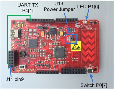
CY8CKIT-042 kit (PSOC 4200)
This kit includes a built-in debugger and connectors that are compatible with many common shield boards compatible with Arduino. The most important feature of this kit pertaining to this application note and measuring current is the power jumper, J13. To measure the current of the PSOC™ 4 MCU device, remove this jumper and place an ammeter across the pins. By doing so, you are measuring only the current of the PSOC™ 4 MCU device and not the rest of the board. This board also includes the LED and the button required to exercise these examples.
Another feature of the board is a USB-to-serial port adapter. By connecting a wire from PSOC™ 4 MCU P4[1] to J11 pin 9, as shown in
Figure 16
, you can use your favorite terminal emulator to monitor the serial output of the AN86233_DeepSleepADC project. The baud rate is 115.2 kbps, 8-bit data, and no parity. For more information on using the USB-to-serial port feature, see the
CY8CKIT-042 – PSOC™ 4 pioneer kit guide
.
Figure 16.
CY8CKIT-042 kit hardware
CY8CKIT-044 and CY8CKIT-046 are similar to CY8CKIT-042 and have similar connections for the switch, LED, and UART Tx lines. See the kit guides provided on the respective web pages for more information on these kits.
CY8CKIT-049-42xx kit (PSOC 4200)
These low-cost kits provide access to all PSOC™ 4 MCU pins, and include a user LED and switch that are compatible with CY8CKIT-042. Power can be provided from one of the “P4VDD” pins on the side or through the USB connector at the end.
Figure 17
shows the kit hardware.
Figure 17.
CY8CKIT-049-42xx kit hardware
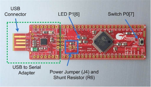
This kit does not have a built-in debugger, but it includes a USB-to-serial adapter that can be used to bootload the project. The projects must first be modified to include a bootloadable component to use this interface. If you have a MiniProg3 program and debug kit (CY8CKIT-002), you can connect it directly to a user-installed connector at the bottom-right corner of the board. For more information on how to use the USB-to-serial adapter for bootloading, download the kit documentation from the website.
To measure the project current with the kit when the kit is powered from the USB port, remove the zero-ohm resistor R6, and add pins or wires in J4 that can be connected to an ammeter or digital multimeter (DMM).
The USB-to-serial adapter provides a bootloader interface as well as a serial port adapter to display the output of the example project, AN86233_DeepSleepADC.
CY8CKIT-043 kit (PSOC 4200M)
This kit includes a built-in debugger and has a form factor similar to that of CY8CKIT-049. Power can be provided from one of the “P4VDD” pins on the side or through the USB connector at the end. To measure the project current with the kit when the kit is powered from the USB port, remove the zero-ohm resistor R22, and add pins or wires in J4 that can be connected to an ammeter or DMM.
Figure 18
shows the kit hardware.
Figure 18.
CY8CKIT-043 hardware
This board also contains the LED and switch required to exercise these examples. Another feature it includes is a USB-to-serial port adapter. You can use your favorite terminal emulator to monitor the serial output of the AN86233_DeepSleepADC project without making any special hardware connection. The baud rate is 115.2 kbps, 8-bit data, and no parity. For more information on using the USB-to-serial port feature, see the
KitProg user guide
.
8
Other compatible pins also can be used to connect to the UART Tx. On CY8CKIT-044 and CY8CKIT-046, the pins listed in the table are hardwired to the onboard KitProg USB-to-UART bridge.
9
Other compatible pins also can be used to connect to the UART Tx. On CY8CKIT-049 and CY8CKIT-043, the pins listed in the table are hardwired to the onboard USB-to-UART bridge.
Measuring current with a DMM
When using a DMM to measure the current, it is important to know the value of the shunt resistor in the DMM. DMMs have one or more (shunt) resistors between the current inputs. These resistors can range from less than an ohm to more than 10 kΩ. There is no standard value for the shunt resistor between brands or even models from the same vendor. It is important to review your meter’s manual and learn the value of the shunt resistor because there is always a voltage drop across this shunt. This means that the PSOC™ 4 MCU device does not see the same voltage as that which you are supplying.
If the shunt resistor in your meter is 1 Ω or less, you will see only a few millivolts of drop when measuring PSOC™ 4 MCU current, and you can ignore it. If the shunt resistor is 1 kΩ, which some vendors use for low-current measurements, a 1-mA current will result in a drop of 1 V. Also, when changing ranges, be careful that the DMM does not do a break-before-make, or the power will be cycled and your project will be reset.
For extremely low currents in Deep Sleep, Hibernate, and Stop modes, a good technique is to use a zero- or low-resistance shunt until the device enters low-power mode. After entering low-power mode, the code should keep the device in that mode and switch to a high-resistance shunt for current measurement.
As an alternative to relying on the DMM shunt, both kits include a place for a shunt resistor. CY8CKIT-049-42xx has a zero-ohm shunt (R6). This can be replaced by a small resistor and measurement of the voltage across the shunt with a voltmeter. You can then easily determine the current. A shunt between 1 Ω and 100 Ω should work well for most applications. CY8CKIT-042 also has place for a shunt resister (R6) next to J13.
Approximating the power consumption
The device datasheet and PSOC™ Creator component datasheets provide sufficient information to estimate the power consumption for a given project. To simplify this process, a spreadsheet has been provided that includes typical power requirements for a wide range of internal components. This spreadsheet,
PSoC4_Power_Estimator.xlsx
, is located on the
AN86233 page
. Because every project is different, the power calculation provided by this spreadsheet is only an estimate, but it should be close enough to provide good feedback before your design is complete. There are several tabs in the spreadsheet; make sure you read the “Instructions” tab before entering your data.
Reusing the examples
The code examples mentioned in the earlier section can be ported to various PSOC™ 4 MCU devices, kits, or both. Before porting any code examples, note the following:
PSOC™ 4 MCU devices do not share all the same blocks.
Pinouts change from kit to kit. Some pins may need to be moved. See the Pin layout tab in PSOC™ Creator.
To port the code to a new device, in PSOC™ Creator, select
selector and change to the target device. In some cases, a resource used by a code example (for example, an IP block) is not supported on another device. In that case the example will not work. If you build the code targeted at such a device, you will get errors. See the device datasheet for information on what a particular device supports.
Summary
Power consumption can make the difference between a good idea and a successful design. By taking advantage of the many power-saving features available in PSOC™ 4 MCU, you can optimize your design and ensure that it consumes the lowest amount of power.
Related application notes
These application notes give you more information relating to topics that are not fully discussed here:
Revision history
Revision | Date of release | Description of change |
|---|---|---|
** | 2013-04-18 | New application note |
*A | 2013-05-09 | Updated links Updated example project section |
*B | 2015-04-09 | Replaced example project with three other projects Added typical current and wakeup times Updated content on UnFreezeIo() and FreezeIo() APIs Updated low-power APIs Included power calculation spreadsheet Many minor changes Sunset update |
*C | 2015-06-19 | Clarified retention of UDBs when exiting deep sleep and hibernate in Table 2. Cleaned up several minor typos |
*D | 2015-08-24 | Updated the document for PSOC™ 4200L MCU Updated the power calculation spreadsheet |
*E | 2015-12-31 | Updated the projects to PSOC™ Creator 3.3 SP1 |
*F | 2016-03-22 | Updated the document for PSOC™ analog coprocessor Updated the power calculation spreadsheet |
*G | 2017-10-04 | Updated projects to PSOC™ Creator 4.1 update 1 Removed the ILO calibration component from AN86233_DeepSleepADC project Updated template |
*H | 2018-04-18 | Added support for PSOC™ 4100PS throughout the document Updated power estimator spreadsheet and PSOC™ Creator projects |
*I | 2021-11-04 | Added support for ModusToolbox™ software and the peripheral driver library Updated to Infineon template |
*J | 2025-03-27 | Template update, no content update |
Trademarks
PSOC™, formerly known as PSoC™, is a trademark of Infineon Technologies. Any references to PSoC™ in this document or others shall be deemed to refer to PSOC™.
1
Retention: The configuration and state of the peripheral are retained. The peripheral resumes its operation when the device enters Active mode.
2
The state of VDAC, as well as any UDB-based function, is preserved by calling a
_Sleep()
function before entering deep sleep, and restored by calling a
_WakeUP()
function after exiting Deep Sleep mode.
3
When exiting Hibernate mode, all UDB-based functions are reinitialized because the PSOC™ 4 MCU device goes through a reset.
4
Frozen: The configuration, mode, and state of all GPIOs are locked. Changing the GPIO state is not possible until the device enters Active mode and the GPIOs are unlocked.
5
The WDT can be configured to generate both interrupts and resets at different intervals. See the technical reference manual (TRM) for the applicable PSOC™ 4 MCU device family.
6
XRES triggers a full system reset. All states including frozen I/Os are lost. In this case, the cause of wakeup is not detectable after the device restarts.
7
ModusToolbox™ software environment does not support Hibernate or Stop modes.
8
Other compatible pins also can be used to connect to the UART Tx. On CY8CKIT-044 and CY8CKIT-046, the pins listed in the table are hardwired to the onboard KitProg USB-to-UART bridge.
9
Other compatible pins also can be used to connect to the UART Tx. On CY8CKIT-049 and CY8CKIT-043, the pins listed in the table are hardwired to the onboard USB-to-UART bridge.