AN79953 Getting started with PSOC™ 4 MCU
About this document
Scope and purpose
This application note introduces you to
PSOC™ 4
, an Arm® Cortex®-M0/M0+ based programmable system-on-chip. It helps you explore the
PSOC™ 4
architecture and development tools and explains you how to create your first project using PSOC™ Creator and ModusToolbox™, the development tools for
PSOC™ 4
; also guides you to more resources to accelerate in-depth learning about
PSOC™ 4
.
Intended audience
This application note is intended for engineers new to PSOC™ and ModusToolbox™, and those with experience in working with embedded microcontrollers.
Associated part family
All
PSOC™ 4
parts
Software version
4.4 SP2 or higher,
ModusToolbox™
3.2 or higher.
More code examples? We heard you.
To
access an ever-growing list of PSOC™ 4 code examples using ModusToolbox™, please visit the GitHub site
. You can also explore the
PSOC™
video library
.
Introduction
PSOC™ 4
is a true programmable embedded system-on-chip integrating custom analog and digital peripheral functions, memory, and an Arm® Cortex�®-M0 or Cortex®-M0+ microcontroller on a single chip. This type of system is different from most mixed-signal embedded systems, which use a combination of a microcontroller unit (MCU) and external analog and digital peripherals. These systems typically require many integrated circuits in addition to the MCU, such as opamps, ADCs, and Application-specific Integrated Circuit (ASICs).
PSOC™ 4
provides a low-cost alternative to the combination of MCU and external ICs. In addition to reducing overall system cost, the programmable analog and digital subsystems allow great flexibility, in-field tuning of the design, and speedy time to market.
The capacitive touch-sensing feature in
PSOC™ 4
, known as CAPSENSE™, offers unprecedented signal-to-noise ratio; best-in-class liquid tolerance and a wide variety of sensor types such as buttons, sliders, trackpads, and proximity sensors.
PSOC™ 4
offers a best-in-class current consumption of 150 nA while retaining SRAM, programmable logic, and the ability to wake up from an interrupt.
PSOC™ 4
consumes only 20 nA while maintaining wakeup capability in its non-retention power mode. The
PSOC™ 4
family of devices also contain
PSOC™ 4
Bluetooth® LE, which integrates a Bluetooth® Low Energy radio system. For more details on
PSOC™ 4
Bluetooth® LE, see
AN91267
.
Using this document
The next few pages describe
PSOC™ 4
and the advantages of designing with PSOC™, ModusToolbox™, and PSOC™ Creator. Or, you can jump right in and quickly build a simple design in ModusToolbox™ – go to
Getting started with PSOC 4000T design
. If you are using PSOC™ Creator – go to
My first
PSOC™ 4
design using PSOC™ Creator
.
Development ecosystem
PSOC resources
The wealth of information available on the
Infineon
webpage can help you select the right PSOC™ device and, additionally, integrate the device into your designs efficiently and effectively. The following is an abbreviated list for
PSOC™ 4
:
Overview: PSOC™ portfolio
Product selectors: PSOC™ 4. In addition, PSOC™ Creator includes a device selection tool.
Datasheets describe and provide electrical specifications for each family.
Application notes cover a broad range of topics, from basic to advanced level, and include the following:
AN88619: PSOC™ 4 hardware design considerations
AN73854: Introduction to bootloaders
AN89610: Arm® Cortex® code optimization
AN86233:PSOC™ 4 low-power modes and power reduction techniques
AN57821: Mixed-signal circuit board layout
AN89056:PSOC™ 4- IEC 60730 class B and IEC 61508 SIL Safety Software Library
AN64846: Getting started with CAPSENSE™
AN85951:PSOC™ 4 and PSOC™ 6 MCU CAPSENSE™ design guide
AN239751: Flyback inductive sensing (ISX) design guide
Code examples demonstrate product features and usage
Technical reference manuals(TRMs): Provide detailed descriptions of the architecture and registers in each PSOC™ 4 device family.
PSOC™ 4 programming specification provides the information necessary to program PSOC™ 4 nonvolatile memory.
CY8CKIT-040,CY8CKIT-042,CY8CKIT-044,CY8CKIT-046,CY8CKIT-042-BLE,CY8CKIT-045S, and CY8CKIT-041S-MAXPSOC™ 4 Pioneer kits are easy-to-use and inexpensive development platforms. These include connectors for Arduino-compatible shields and Digilent Pmod daughter cards.
CY8CKIT-043,CY8CKIT-145-40XX,CY8CKIT-147,CY8CKIT-149,CY8CPROTO-040T,CY8CPROTO-040T-MS, and CY8CPROTO-041TP are very low-cost prototyping platforms for sampling PSOC™ 4 devices.
CY8CKIT-040T is a low-cost evaluation kit showing the low power CAPSENSE™, low power wake on touch and liquid tolerant features of the PSOC™ 4000T device.
The MiniProg3 or MiniProg4 kit provides an interface for flash programming and debug.
Integrated Development Environment (IDE): There are two development platforms that can be used for application development with PSOC™ 4 – ModusToolbox™ and PSOC™ Creator.
PSOC™ 4 CAD libraries provide footprint and schematic support for common tools. IBIS models are also available.
Training videos are available in Infineon website on a wide range of topics including the PSOC™ 4101 series
Infineon community enables connection with fellow PSOC™ developers around the world, 24 hours a day, 7 days a week, and hosts a dedicated PSOC™ 4 MCU community.
Firmware/application development
There are two development platforms that you can use for application development with
PSOC™ 4000T
:
ModusToolbox™:
This software includes configuration tools, low-level drivers, middleware libraries, and other packages that enable you to create MCU and wireless applications. All tools run on Windows, macOS, and Linux. ModusToolbox™ includes an Eclipse IDE, which provides an integrated flow with all the ModusToolbox™ tools. Other IDEs such as Visual Studio Code, IAR Embedded Workbench and Arm® MDK (μVision) are also supported.
ModusToolbox™ software supports stand-alone device and middleware configurators. Use the configurators to set the configuration of different blocks in the device and generate code that can be used in firmware development.
ModusToolbox™ supports all PSOC™ 6 MCU and the latest
PSOC™ 4
MCU devices.
Table 1
lists the supported
PSOC™ 4
devices. Infineon recommends you to use ModusToolbox™ for all application development for supported
PSOC™ 4
devices. For more information, see ModusToolbox™ tools package user guide.
Table 1.List of PSOC™ 4 devices supported in ModusToolbox™ Devices
1
ModusToolbox™
PSOC™ Creator
PSOC™ 4000S, PSOC™ 4100S, PSOC™ 4100S Plus, PSOC™ 4100S Plus 256K
Yes
Yes
PSOC™ 4100S Max, PSOC™ 4000T, PSOC™ 4100T Plus
Yes
No
All other
PSOC™ 4
devices
No
Yes
The libraries and enablement software are available on
GitHub
.
ModusToolbox™ tools and resources can also be used in the command line. For more information, see the “ModusToolbox™ build system” section in the
ModusToolbox™ tools package user guide
.
PSOC™ Creator:PSOC™ Creator is a free Windows-based IDE. It enables concurrent hardware and firmware design of PSOC™ 3,PSOC™ 4, PSOC™ 5LP, and PSOC™ 6 MCU systems. Applications are created using schematic capture and over 150 pre-verified, production-ready peripheral Components.
Installing the ModusToolbox tools package
Choosing an IDE
helps you to choose an appropriate IDE.
Figure 1.
Choosing an IDE
ModusToolbox™ software, the latest-generation toolset, is supported across Windows, Linux, and macOS platforms. ModusToolbox™ software supports 3rd-party IDEs, including the Eclipse IDE, Visual Studio Code, Arm® MDK (μVision), and IAR Embedded Workbench. The tools package includes an implementation for all the supported IDEs. The tools support all
PSOC™ 4000T
s. The associated BSP and library configurators also work on all three host operating systems.
Figure 2.
ModusToolbox™ environment
Certain features of the
PSOC™ 4000T
, such as UDBs (Universal Digital Blocks) and USB are not supported in ModusToolbox™ version 2.x and earlier. Newer versions of ModusToolbox™ support the USB host feature and improve the user experience with true multi-core debug support.
It is recommended to use ModusToolbox™ if you want to build an IoT application using IoT devices or if you are using a
PSOC™ 4000T
not supported in PSOC™ Creator.
PSOC™ Creator is the long-standing proprietary tool that runs on Windows only. This mature IDE includes a graphical editor that supports schematic based design entry with the help of Components. PSOC™ Creator supports all
PSOC™
3,
PSOC™
4, and
PSOC™
5LP devices, and a subset of
PSOC™ 4000T
devices.
Choose PSOC™ Creator if you are using a graphical editor for design entry and code generation, and if the
PSOC™
MCU that you are planning to use is supported by the IDE.
ModusToolbox software
ModusToolbox™ software is a set of tools and software that enables an immersive development experience for creating converged MCU and wireless systems, and enables you to integrate our devices into your existing development methodology. These include configuration tools, low-level drivers, libraries, and operating system support, most of which are compatible with Linux-, macOS-, and Windows-hosted environments.
shows a high-level view of what is available as part of ModusToolbox™ software. For a more in-depth overview of the ModusToolbox™ software, see
ModusToolbox™ tools package user guide
.
Figure 3.
ModusToolbox™ software
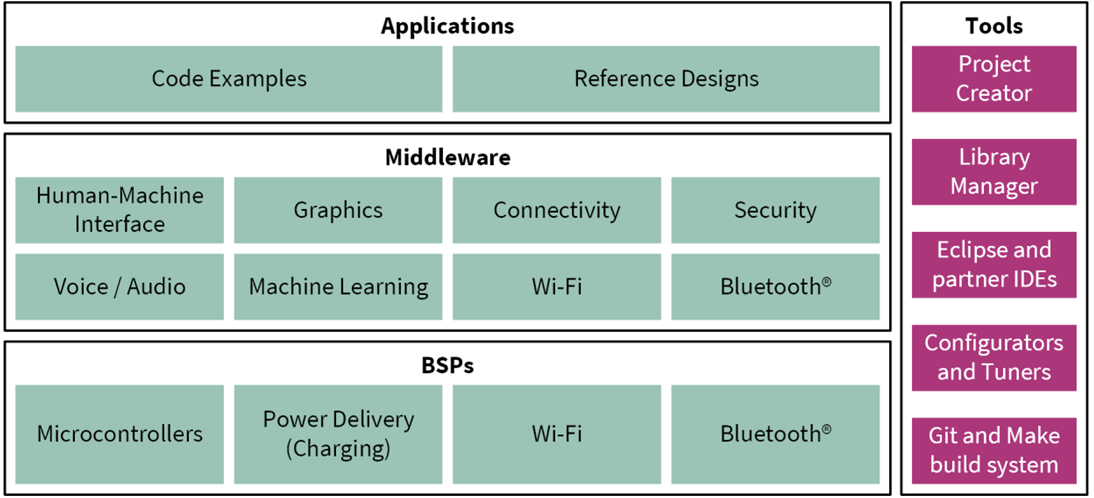
The ModusToolbox™ tools package installer includes the design configurators and tools, and the build system infrastructure.
The build system
infrastructure includes the new project creation wizard that can be run
independent of the Eclipse IDE, the make infrastructure, and other
tools.
This means you choose your compiler, IDE, RTOS, and ecosystem without compromising usability or access to our industry-leading CAPSENSE™ (Human-Machine Interface), AIROC™ Wi-Fi and Bluetooth®, security, and various other features.
One part of the ModusToolbox™ ecosystem is run-time software that helps you rapidly develop Wi-Fi and Bluetooth® applications using connectivity combo devices. See the
ModusToolbox™ run-time software reference guide
for details.
Design configurators are the tools that help you create the configurable code for your BSP/Middleware. Jump to
Configurators
to know more about it.
All the application-level development flows depend on the provided low-level resources. These include:
Board support packages (BSP) – A BSP is the layer of firmware containing board-specific drivers and other functions. The BSP is a set of libraries that provides APIs to initialize the board and access to board level peripherals. It includes low-level resources such as peripheral driver library (PDL) for PSOC™ 4000T and has macros for board peripherals. It uses the HAL to configure the board. Custom BSPs can be created to enable support for end-application boards. See BSP Assistant to create your BSP.
Hardware abstraction layer (HAL)– The hardware abstraction layer (HAL) provides a high-level interface to configure and use hardware blocks on MCUs. It is a generic interface that can be used across multiple product families. The focus on ease-of-use and portability means the HAL does not expose all the low-level peripheral functionality. The HAL wraps the lower level drivers (like PSOC™ 4000T PDL) and provides a high-level interface to the MCU. The interface is abstracted to work on any MCU. This helps you write application firmware independent of the target MCU.
The HAL can be combined with platform-specific libraries (such as PSOC™ 4000T PDL) within a single application. You can leverage the HAL's simpler and more generic interface for most of an application, even if one portion requires lower-level control.
PSOC™ 4000Tperipheral driver library (PDL)– The PDL integrates device header files, start-up code, and peripheral drivers into a single package. The PDL supports the PSOC™ 4000T family. The drivers abstract the hardware functions into a set of easy-to-use APIs. These are fully documented in the PDL API Reference.
The PDL reduces the need to understand register usage and bit structures, thus easing software development for the extensive set of peripherals in the PSOC™ 4000T series. You configure the driver for your application, and then use API calls to initialize and use the peripheral.
Middleware (MW) – Extensive middleware libraries that provide specific capabilities to an application. The available middleware spans across connectivity (OTA, Bluetooth®, AWS IoT, Bluetooth® LE, Secure Sockets) to PSOC™ 4000T-specific functionality (CAPSENSE™, USB, device firmware upgrade (DFU), emWin). All the middleware is delivered as libraries and via GitHub repositories.
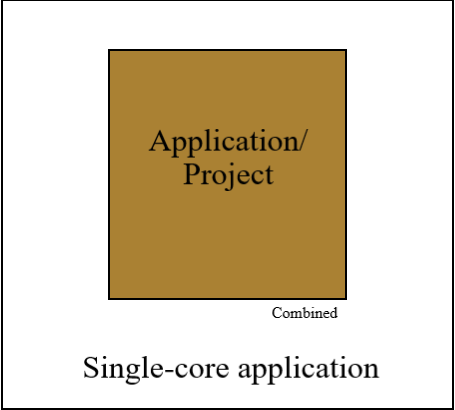
ModusToolbox applications
With the release of ModusToolbox™ v3.x, multi-core support is introduced, which has altered the folder structure slightly from the previous version of ModusToolbox™, but
PSOC™ 4
has single core only.
Figure 4.
Application type
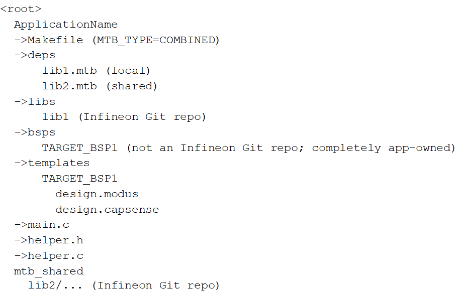
The following shows the new folder structure for an example single-core application:
Figure 5.
Folder structure for single-core applications
PSOC 4
software resources
The software for
PSOC™ 4000T
s includes configurators, drivers, libraries, middleware, as well as various utilities, makefiles, and scripts. It also includes relevant drivers, middleware, and examples for use with IoT devices and connectivity solutions. You can use any or all tools in any environment you prefer.
Configurators
ModusToolbox™ software provides graphical applications called configurators that make it easier to configure a hardware block. For example, instead of having to search through all the documentation to configure a serial communication block as a UART with a desired configuration, open the appropriate configurator and set the baud rate, parity, and stop bits. Upon saving the hardware configuration, the tool generates the "C" code to initialize the hardware with the desired configuration.
There are two types of configurators: BSP configurators that configure items that are specific to the MCU hardware and library configurators that configure options for middleware libraries.
Configurators are independent of each other, but they can be used together to provide flexible configuration options. They can be used stand alone, in conjunction with other tools, or within a complete IDE. Configurators are used for:
Setting options and generating code to configure drivers
Setting up connections such as pins and clocks for a peripheral
Setting options and generating code to configure middleware
For
PSOC™ 4
applications, the available Configurators include:
Device Configurator: Sets up the system (platform) functions and the basic peripherals (for example, UART, Timer, PWM).
CAPSENSE™ Configurator and Tuner: Configures CAPSENSE™ and generates the required code.
Smart I/O Configurator: Configures the Smart I/O.
Each of the above configurators create their own files (For example,
design.cycapsense
for CAPSENSE™). BSP configurator files (For example,
design.modus
or
design.cycapsense
) are provided as part of the BSP with default configurations while library configurators (e.g. design.cybt) are provided by the application. When an application is created based on Infineon BSP, the application makes use of BSP configurator files from the Infineon BSP repo. You can customize/create all the configurator files as per your application requirement using ModusToolbox™ software. See
BSP Assistant
to create your custom BSP. See
ModusToolbox™ help
for more details.
Library management for
PSOC 4000T
The application can have shared/local libraries for the projects. If needed, different projects can use different versions of the same library. The shared libraries are downloaded under the
mtb_shared
directory. The application should use the
deps
folder to add library dependencies. The
deps
folder contains files with the
.mtb
file extension, which is used by ModusToolbox™ to download its git repository. These libraries are direct dependencies of the ModusToolbox™ project.
The Library Manager helps to add/remove/update the libraries of your projects. It also identifies whether particular library has a direct dependency on any other library using the manifest repository available on GitHub, and fetches all its dependencies. These dependency libraries are indirect dependencies of the ModusToolbox™ project. These dependencies can be seen under the
libs
folder. For more information, see the
Library Manager user guide
located at
<install_dir> /ModusToolbox/tools_<version>/library-manager/docs/library-manager.pdf
.
Software development for
PSOC 4000T
The ModusToolbox™ ecosystem provides significant source code and tools to enable software development for
PSOC™ 4000T
s. You use tools to:
Specify how you want to configure the hardware.
Generate code for that purpose, which you use in your firmware.
Include various middleware libraries for additional functionality, like Bluetooth® LE connectivity or FreeRTOS.
This source code makes it easier to develop the firmware for supported devices. It helps you quickly customize and build firmware without the need to understand the register set.
In the ModusToolbox™ environment, you use configurators to configure either the device, or a middleware library, like the Bluetooth® LE stack or CAPSENSE™. The BSP configurator files are used to configure device peripherals, pins, and memory using peripheral driver library code. The middleware is delivered as separate libraries for each feature/function such that it can be used across multiple platforms. For example, abstractionrtos, lwip, usb, etc.
Firmware developers who wish to work at the register level should refer to the driver source code from the PDL. The PDL includes all the device-specific header files and startup code you need for your project. It also serves as a reference for each driver. Because the PDL is provided as source code, you can see how it accesses the hardware at the register level.
Some devices do not support particular peripherals. The PDL is a superset of all the drivers for any supported device. This superset design means:
All API elements needed to initialize, configure, and use a peripheral are available.
The PDL is useful across various PSOC™ 4000Ts, regardless of available peripherals.
The PDL includes error checking to ensure that the targeted peripheral is present on the selected device.
This enables the code to maintain compatibility across products of the
PSOC™ 4000T
family, as long as the peripherals are available. A device header file specifies the peripherals that are available for a device. If you write code that attempts to use an unsupported peripheral, you will get an error at compile time. Before writing code to use a peripheral, consult the datasheet for the particular device to confirm support for that peripheral.
As the following figure shows, with the ModusToolbox™ software, you can:
Choose a BSP (Project Creator).
Create a new application based on a list of starter applications, filtered by the BSPs that each application supports (Project Creator).
Add BSP or middleware libraries (Library Manager).
Develop your application firmware using
the HAL or
PDL for
PSOC™ 4000T
(IDE of choice or command line).
Figure 6.
ModusToolbox™ resources and middleware
ModusToolbox help
The ModusToolbox™ ecosystem provides documentation and training. One way to access it is launching the Eclipse IDE for ModusToolbox™ software and navigating to the following
Help
menu items:
Choose
:
ModusToolbox™ Documentation Index:
Provides brief descriptions and links to various types of documentation included as part the ModusToolbox™ software.
ModusToolbox™ Installation Guide:
Provides instructions for installing the ModusToolbox™ software.
ModusToolbox™ User Guide:
This guide primarily covers the ModusToolbox™ aspects of building, programming and debugging applications. It also covers various aspects of the tools installed along with the IDE.
ModusToolbox™ Training Material: Links to the training material available at https://github.com/Infineon/training-modustoolbox.
- Release Notes
For documentation on Eclipse IDE for ModusToolbox™, choose
:
User Guide:
Provides descriptions about creating applications as well as building, programming, and debugging them using Eclipse IDE
Eclipse IDE Survival Guide
Support for other IDEs
You can develop firmware for
PSOC™ 4000T
s using your preferred IDE such as Eclipse IDE,
IAR Embedded Workbench
,
Keil µVision 5
, or
Visual Studio Code
.
ModusToolbox™ Configurators are stand-alone tools that can be used to set up and configure
PSOC™ 4000T
resources and other middleware components without using the Eclipse IDE. The Device Configurator and middleware configurators use the
design.x
files within the application workspace. You can then point to the generated source code and continue developing firmware in your IDE.
If there is a change in the device configuration, edit the
design.x
files using the configurators and regenerate the code. It is recommended that you generate resource configurations using the configuration tools provided with ModusToolbox™ software.
See
ModusToolbox™ tools package user guide
for details.
PSOC Creator
is an IDE that enables concurrent hardware and firmware editing, compiling, and debugging of PSOC™ systems. Do the following to browse through PSOC™ Creator, as shown in
Figure 7
:
Drag and drop Components to build your hardware system design
Co-design your application firmware with the PSOC™ hardware
Configure Components with config tools
Explore the library of more than 100 Components
Review Component datasheets
Figure 7.
Features of PSOC™ Creator features
PSOC Creator help
Download the PSOC™ Creator’s latest version from the
PSOC™ Creator
home page, launch the PSOC™ Creator, and navigate to the following:
Quick Start Guide: Choose Help > Documentation > Quick Start Guide. This guide gives you the basics for developing PSOC™ Creator projects.
Simple Component example projects: Choose File > Open > Example projects. These example projects demonstrate how to configure and use PSOC™ Creator Components.
System Reference Guide: Choose Help > System Reference > System Reference Guide. This guide lists and describes the system functions provided by PSOC™ Creator.
Component datasheets: Right-click a Component and select Open Datasheet. Visit the PSOC™ 4 Component datasheets page for a list of all PSOC™ 4 Component datasheets.
PSOC™ Creator training videos: These videos provide step-by-step instructions on how to get started with PSOC™ Creator.
Document Manager: PSOC™ Creator provides a document manager to help you to find and review document resources easily. To open the document manager, choose the menu item Help > Document Manager.
Technical support
If you have any questions, our technical support team is happy to assist you. You can create a support request on the
Technical support
page. The support team monitors and responds to your questions, issues, and bug reports posted on the
GitHub
repositories.
PSOC 4 feature set
PSOC™ 4
has an extensive set of features, which include a CPU and memory subsystem, a digital subsystem, an analog subsystem, and system resources, as shown in
Figure 8
. The following sections describe each feature. For more information, see the
PSOC™ 4
family device datasheets, technical reference manuals (TRMs), and application notes listed in
PSOC™ resources
.
Figure 8.
PSOC™ 4000T architecture
The
PSOC™ 4
portfolio consists of several families of Arm® CM0 and CM0+ microcontrollers. Most devices in the portfolio have CAPSENSE™ technology for capacitive-sensing applications. Other key features of the
PSOC™ 4
portfolio include a customizable analog front end through programmable analog blocks and wired and wireless connectivity options such as USB, Controller Area Network (CAN), and Bluetooth® LE. These unique features make
PSOC™ 4
the industry’s most flexible and scalable low-power mixed-signal architecture. The
PSOC™ 4
devices are classified as different families, as shown in
Table 2
, based on different features.
Classification | Family | Features | Details |
|---|---|---|---|
Entry level | PSOC™ 4 000 family | CAPSENSE™ | |
Intelligent analog | PSOC™ 4 100 family | CAPSENSE™ + Programmable Analog | |
Programmable digital | PSOC™ 4 200 family | CAPSENSE™ + Programmable Analog + Programmable Digital Blocks | |
Application specific | PSOC™ 4 500 family | CAPSENSE™ + Motor Control | |
PSOC™ 4 700 family | CAPSENSE™ + Inductive Sensing | ||
Analog coprocessor 2 | PSOC™ 4 A00 family | CAPSENSE™ + Programmable Analog Blocks |
Note:
In
Table 3
and
Table 4
, the columns highlighted in green indicate that the device family is supported in ModusToolbox™.
Features | PSOC™ 4000 | PSOC™ 4000S | PSOC™ 4000T | ||
|---|---|---|---|---|---|
CPU | 16-MHz Cortex®-M0 | 48-MHz Cortex®-M0+ | 48-MHz Cortex®-M0+ | ||
Flash memory | 16 KB | 32 KB | 64 KB | ||
SRAM | 2 KB | 4 KB | 8 KB | ||
GPIOs | 20 | 36 | 21 | ||
CAPSENSE™ | Sense pins | 16 | 35 | 19 | |
Ultra-Low Power Wake on Touch (WoT) | No | No | Yes | ||
CAPSENSE™ IP Generation | Fourth-generation | Fifth-generation | Fifth-generation Low Power | ||
Single-slope ADC (10-bit 46-ksps) | None | 1 | None | ||
Comparators | 1 CSD comparator with a fixed threshold (1.2 V) | Two low-power comparators with wakeup feature | None | ||
IDACs 3 | One 7-bit and one 8-bit | Two 7-bits | None | ||
Smart I/O ports | None | 2 | None | ||
Power supply range | 1.71 V to 5.5 V | 1.71 V to 5.5 V | 1.71 V to 5.5 V | ||
Low-power modes | Deep Sleep at 2.5 µA | Deep Sleep at 2.5 µA | Deep Sleep at 2.5 µA | ||
Segment LCD drive | None | 4 COM segment LCD drive | None | ||
Serial communication | One I2C | Two SCBs with programmable I2C, SPI, or UART | 1 SCB with programmable I2C, SPI, or UART. 1 SCB having I 2 C only | ||
Timer Counter Pulse-Width Modulator (TCPWM) | 1 | 5 | 2 | ||
Clocks | Internal main oscillator (IMO) | 24 MHz/32 MHz | 24 MHz to 48 MHz | 24 MHz to 48 MHz | |
Internal low-speed oscillator (ILO) | 32-kHz internal ILO | 40 kHz | 40 kHz | ||
Watch crystal oscillator (WCO) | None | 32-kHZ | None | ||
Power supply monitoring | Power-on reset (POR)Brown-out detection (BOD) | POR, BOD | POR, BOD | ||
Supported kit | CY8CKIT-040T PSOC™
4000T CAPSENSE™ Evaluation
Kit , CY8CPROTO-040T PSOC™ 4000T CAPSENSE™ Prototyping Kit , and CY8CPROTO-040T-MS Multi-Sense Prototyping Kit | ||||
Supported IDE | , ModusToolbox™ | ||||
Features | PSOC™ 4100 | PSOC™ 4100S | PSOC™ 4100S Plus | PSOC™ 4100S Plus 256K | PSOC™ 4100PS | PSOC™ 4100M | PSOC™ 4100 BL 4 | PSOC™ 4100S Max | PSOC™ 4100T Plus | |
|---|---|---|---|---|---|---|---|---|---|---|
CPU | 24-MHz Cortex®-M0 | 48-MHz Cortex®-M0+ | 48-MHz Cortex®-M0+ | 48-MHz Cortex®-M0+ | 48-MHz Cortex®-M0+ | 24-MHz Cortex®-M0 | 24-MHz Cortex®-M0 | 48-MHz Cortex®-M0+ | 48-MHz Cortex®-M0+ | |
DMA | N/A | N/A | 8 channels | 8 channels | 8 channels | 8 channels | 8 channels | 16 channels | 8 channels | |
Flash memory | 32 KB | 64 KB | 128 KB | 256 KB | 32 KB | 128 KB | 256 KB | 384 KB | 128 KB | |
SRAM | 4 KB | 8 KB | 16 KB | 32 KB | 4 KB | 16 KB | 32 kB | 32 KB | 32 KB | |
GPIOs | 36 | 36 | 54 | 54 | 38 | 55 | 36 | 84 | 53 | |
CAPSENSE™ | 1 channel, 35 sensors | 1 channel, 35 sensors | 1 channel, 53 sensors | 1 channel, 53 sensors | 1 channel, 33 sensors | 2 channels, 54 sensors | 1 channel, 35 sensors | 2 channels, 80 sensors (32 control mux) | 1 channel, 32 sensors | |
12-bit SAR ADC with sequencer | 806-KSPS | 1-MSPS | 1-MSPS | 1-MSPS | 1-MSPS | 806-KSPS | 806-KSPS | 1-MSPS | 1-MSPS | |
Opamps (programmable) | 2 | 2 | 2 | 2 | 4/PGA | 4 | 2 | 2 | None | |
Programmable Voltage Reference (PVref) | None | None | None | None | Four channels | None | None | None | None | |
Voltage DAC (VDAC) | None | None | None | None | Two 13-bit VDAC | None | None | None | None | |
Comparators (low power with wakeup feature) | 2 | 2 | 2 | 2 | 2 | 2 | 2 | 2 | None | |
IDACs 5 | One 7-bit and one 8-bit | Two 7-bits | Two 7-bits | Two 7-bits | Two 7-bits | Two 7-bits and two 8-bits | One 7-bit and one 8-bit | None | None | |
Smart I/O ports | None | 2 | 3 | 2 | 1 | None | None | 3 | 1 | |
Power supply range | 1.71 V to 5.5 V | 1.71 V to 5.5 V | 1.71 V to 5.5 V | 1.71 V to 5.5 V | 1.71 V to 2.5 µA | 1.71 V to 5.5 V | 1.71 V to 5.5 V | 1.71 V to 5.5 V | 1.71 V to 5.5 V | |
Low-power modes | Deepsleep | 1.3 µA | 2.5 µA | 2.5 µA | 2.5 µA | 2.5 µA | 1.35 µA | 2.5 µA | 2.5 µA | 2.5 µA |
Hibernate | 150 nA | NA | NA | NA | NA | 150 nA | NA | NA | None | |
Stop | 20 nA | NA | NA | NA | NA | 35 nA | NA | NA | None | |
Segment LCD drive | 4 COM | 4 COM | 4 COM | 4 COM | 4 COM | 4 COM | 4 COM | 4 COM | None | |
SCBs with programmable I2C, SPI, or UART | 2 | 3 | 5 | 5 | 3 | 4 | 2 | 5 | 5 (2 SCB, 3 UART) | |
TCPWM | 4 | 5 | 8 | 8 | 8 | 8 | 4 | 8 | 6 | |
CAN | None | None | 1 | None | None | None | None | 1 | None | |
BLE | None | None | None | None | None | None | 4.1/4.2 | None | None | |
Clocks | IMO | 3 MHz to 24 MHz | 24 MHz to 48 MHz | 24 MHz to 48 MHz | 24 MHz to 48 MHz | 24 MHz to 48 MHz | 3 MHz to 48 MHz | 24 MHz to 48 MHz | 24 MHz to 48 MHz | 24 MHz to 48 MHz |
ILO | 32 kHz | 40 kHz | 40 kHz | 40 kHz | 40 kHz | 32 kHz | 40 kHz | 40 kHz | 40 kHz | |
WCO | Nil | 32 kHz | 32 kHz | 32 kHz | 32 kHz | 32 kHz | 32 kHz | 32 kHz | 32 kHz | |
Power supply monitoring | POR, BOD, Low-voltage detection (LVD) | POR, BOD | POR, BOD | POR, BOD | POR, BOD | POR, BOD, LVD | POR, BOD, LVD | POR, BOD | POR, BOD | |
Supported kit | PSOC™ 4100T Plus CAPSENSE™ prototyping kit | |||||||||
Supported IDE | , ModusToolbox™ | , ModusToolbox™ | , ModusToolbox™ | ModusToolbox™ | ||||||
Features | PSOC™ 4200 | PSOC™ 4200DS | PSOC™ 4200M | PSOC™ 4200L | PSOC™ 4200 BL 6 | |
|---|---|---|---|---|---|---|
CM0 CPU | 48 MHz Cortex®-M0 | 48 MHz Cortex®-M0 | 48 MHz Cortex®-M0 | 48 MHz Cortex®-M0 | 48 MHz Cortex®-M0 | |
DMA | None | 8 channels | 8 channels | 32 channels | None | |
Flash memory | 32 KB | 64 KB | 128 KB | 256 KB | 256 KB | |
SRAM | 4 KB | 8 KB | 16 KB | 32 KB | 32 KB | |
GPIOs | 36 | 21 | 55 | 96 | 36 | |
CAPSENSE™ | 1 channel, 35 sensors | None | 2 channels, 54 sensors | 2 channels, 94 sensors | 1 channel, 35 sensors | |
ADC (12-bit, 1-MSPS SAR ADC with sequencer) | 1 | None | 1 | 1 | 1 | |
Opamps (programmable) | 2 | None | 2 | 4 | 2 | |
Comparators (low power with wakeup feature) | 2 | 2 | 2 | 2 | 2 | |
IDACs 7 | One 7-bits and one 8-bit | None | Two 7-bits and two 8-bits | Two 7-bits and two 8-bits | One 7-bit and one 8-bit | |
Programmable logic blocks (UDBs) | 4 | 4 | 4 | 8 | 4 | |
Smart I/O ports | None | 1 | None | None | None | |
Power supply range | 1.71 V to 5.5 V | 1.71 V to 5.5 V | 1.71 V to 5.5 V | 1.71 V to 5.5 V | 1.71 V to 5.5 V | |
Low-power modes | Deep Sleep | 1.3 µA | 2 µA | 1.3 µA | 1.3 µA | 1.5 µA |
Hibernate | 150 nA | NA | 150 nA | 150 nA | 150 nA | |
Stop | 20 nA | NA | 20 nA | 20 nA | 20 nA | |
Segment LCD drive | 4 COM | None | 4 COM | 8 COM | 4 COM | |
SCBs with programmable I2C, SPI, or UART | 2 | 3 | 4 | 4 | 2 | |
TCPWM | 4 | 4 | 8 | 8 | 4 | |
CAN | None | None | 2 | 2 | None | |
BLE | None | None | None | None | 4.1/4.2 | |
USB Full Speed Device Controller (USB) | None | None | None | Yes | None | |
Clocks | IMO | 3 MHz to 48 MHz | 3 MHz to 48 MHz | 3 MHz to 48 MHz | 3 MHz to 48 MHz | 3 MHz to 48 MHz |
ILO | 32 kHz | 40 kHz | 32 kHz | 32 kHz | 32 kHz | |
WCO | None | None | 32 kHz | 32 kHz | 32 kHz | |
External crystal oscillator (ECO) | None | None | 4 MHz to 33 MHz | None | None | |
Power supply monitoring | POR, BOD, LVD | POR, BOD | POR, BOD, LVD | POR, BOD, LVD | POR, BOD, LVD | |
Supported kit | ||||||
Supported IDE | ||||||
Features | PSOC™ 4500S | PSOC™ 4700S | |
|---|---|---|---|
CM0+ CPU | 48 MHz Cortex®-M0+ | 48 MHz Cortex®-M0+ | |
DMA | 8 channels | None | |
Flash memory | 256 KB | 32 KB | |
SRAM | 32 KB | 4 KB | |
GPIOs | 53 | 36 | |
CAPSENSE™ | 1 channel, 52 sensors | 1 channel, 35 sensors | |
MagSense | None | 1 channel | |
ADC | Two 12-bits, 1-MSPS SAR ADCs with sequencer | 10-bit, 16.8-ksps Single slope ADC | |
Opamps (programmable) | 4 | None | |
Comparators (low power with wakeup feature) | 2 | 2 | |
IDACs 8 | Two 7-bits | Two 7-bits | |
Smart I/O ports | 2 | 2 | |
Power supply range | 1.71 V to 5.5 V | 1.71 V to 5.5 V | |
Low-power modes | Deep Sleep | 1.3 µA | 2.5 µA |
Hibernate | 150 nA | NA | |
Stop | 20 nA | NA | |
Segment LCD drive | 4 COM | 8 COM | |
SCBs with programmable I2C, SPI, or UART | 5 | 2 | |
TCPWM | 8 | 5 | |
Motor Control Acceleration (MCA) | 2 | None | |
Clocks | IMO | 24 MHz to 48 MHz | 24 MHz to 48 MHz |
ILO | 40 kHz | 40 kHz | |
WCO | 32 kHz | 32 kHz | |
ECO | 4 MHz to 33 MHz | None | |
Power supply monitoring | POR, BOD | POR, BOD | |
Supported kit | |||
Supported IDE | |||
3
IDACs are available only when CAPSENSE™ is not in use. See the respective PSOC™ 4 architecture TRM for more details.
5
IDACs are available only when CAPSENSE™ is not in use. See the respective PSOC™ 4 architecture TRM more details.
7
IDACs are available only when CAPSENSE™ is not in use. See the respective PSOC™ 4 architecture TRM for more details.
8
IDACs are available only when CAPSENSE™ is not in use. See the respective PSOC™ 4 architecture TRM for more details.
PSOC is more than an MCU
shows that a typical MCU contains a CPU (such as 8051 or an Arm® Cortex®) with a set of peripheral functions such as ADCs, DACs, UARTs, SPIs, and general I/O, all linked to the CPU’s register interface. Within the MCU, the CPU is the “heart” of the device – the CPU manages everything from setup to data movement to timing. Without the CPU, the MCU cannot function.
shows that PSOC™ is quite different. With PSOC™, the CPU, analog, digital, and I/O are equally important resources in a programmable system. It is the system’s interconnect and programmability that is the heart of PSOC™ – not the CPU. The peripheral analog and digital are interconnected with a highly configurable matrix of signal and data bus meshing that allows you to create custom designs that meet your application requirements. You can program PSOC™ to emulate an MCU, but you cannot program an MCU to emulate PSOC™.
Figure 9.
Typical MCU block diagram
Figure 10.
PSOC™ block diagram
A typical MCU requires CPU firmware to process state machines, use a timer for timing, and drive an output pin. Therefore, the functional path is always through the CPU. However, with PSOC™, asynchronous parallel processing is possible. You can configure a PSOC™ to have elements that operate independently from the CPU. The projects included with this application note demonstrate this concept. The PSOC™ is configured to make an LED blink without writing any code for the CPU as mentioned in section
Part 1: Create the design
.
The concept of PSOC Creator Components
One other important thing about PSOC™ is the availability of PSOC™ Creator IDE. In PSOC™ Creator, different PSOC™ resources are organized as graphical elements called Components, which can be dragged and dropped onto a schematic to quickly build designs. Every peripheral in PSOC™ is available as a pre-validated PSOC™ Creator Component – PWM Component, ADC Component, DAC Component, CAPSENSE™ Component, UART Component and so on. The availability of pre-validated Components in the PSOC™ Creator significantly reduces the development time. It also allows you to quickly make changes in the design using graphical options.
For example, configuring a PWM to blink an LED in a typical microcontroller involves the following:
Locate the registers corresponding to the PWM block.
Calculate the values to be written to the PWM registers based on the required PWM period and duty cycle.
Write many lines of code to configure the PWM registers, set the pin drive mode, and to connect the PWM output to the pin. Many MCUs do not offer alternate pins to connect to the internal blocks.
To implement the same functionality in PSOC™ is a trivial exercise, as you will find out later in this application note. Later, if you need to reconfigure the same PWM block to a Timer, you do not need anything more than a few mouse clicks in PSOC™ Creator.
The PSOC™ also has programmable digital blocks known as Universal Digital Blocks (UDBs). PSOC™ Creator also provides several Components made of UDBs such as UART, SPI, I2C, Timer, PWM, Counter, Digital Gates (AND, OR, NOT, XOR, and so on), and many more. You can even create your own custom state machines and digital logic using the UDBs in PSOC™ Creator. The method to create your own custom PSOC™ Creator Components is provided in the
PSOC™ Creator Component author guide
.
Getting started with PSOC 4000T design
This section
provides
the following:
Demonstrate how to build a simple PSOC™ 4000T-based design and program it on to the development kit
Makes it easy to learn PSOC™ 4000T design techniques and how to use the ModusToolbox™ software with different IDEs.
Note:
You can use any supported IDE, but this section uses the Eclipse IDE as an example.
Prerequisites
Before you get started, make sure that you have the appropriate development kit for your
PSOC™ 4000T
product line and have installed the required software. You also need internet to access the GitHub repositories during project creation.
Hardware
Testing this design requires one of the kits listed in
Table 7
, which has an integrated programmer.
Kit name | Kit type | Supported device family | Part number |
|---|---|---|---|
CY8CKIT-145 | Prototyping kit | PSOC™ 4 000S | CY8C4045AZI-S413 |
CY8CKIT-149 | Prototyping kit | PSOC™ 4 100S Plus | CY8C4147AZI-S475 |
CY8CKIT-041S-Max | Pioneer kit | PSOC™ 4 100S Max | CY8C4149AZI-S598 |
CY8CKIT-040T | Evaluation kit | PSOC™ 4000T | CY8C4046LQI-T452 |
CY8CPROTO-040T | Prototyping kit | PSOC™ 4 000T | CY8C4046LQI-T452 |
CY8CPROTO-041TP | Prototyping kit | PSOC™ 4100T Plus | CY8C4147AZQ-T495 |
CY8CPROTO-040T-MS | Prototyping kit | PSOC™ 4000T | CY8C4046LQI-T452 |
Software
ModusToolbox™ software 3.2 or above.
After installing the software, see the ModusToolbox™ tools package user guide to get an overview of the software.
Using these instructions
These instructions are grouped into several sections. Each section is dedicated to a phase of the application development workflow. The major sections are:
Create a BSP for your board
Create a new application
View and modify the design configuration
Write firmware
Build the application
Program the device
Test your design
If you are familiar with developing projects using ModusToolbox™, you can use one of the supported starter applications for your kit, such as
Hello World
or
Blinky
directly. This starter application is a complete project, which can run on supported kits without any additional code or configuration. This design is developed for the kits listed in
Table 7
. You can test this example by selecting the appropriate kit while creating the application. You can go through the instructions in the README.md file and observe how the steps are implemented in the code example.
Even if you are creating a different application from scratch following the instructions in this application note, you can use this code example as a reference.
About the design
This design uses the
PSOC™ 4
MCU to blink an LED. On kits that support UART, the “Hello World” message is printed to the serial port stream.
Create a BSP for your board
All ModusToolbox™ applications require a target BSP. Infineon provides BSPs for all of our kits (including the kits mentioned in
Table 7
) and for each chip architecture to use as a starting point. When working with your own hardware, you can modify an Infineon BSP to match the hardware. The BSP Assistant helps to simplify the process. If you are developing for your own hardware, create a custom BSP by following the steps given in
ModusToolbox™ BSP Assistant user guide
. Section
Opening the Device Configurator
describes how the configuration of the custom BSP can be edited.
Create a new application
This section takes you on a step-by-step guided tour of the new application process. It uses the
Empty App
Empty App
Empty PSOC4 App
starter application and manually adds the functionality from the
Hello World
starter application. The Eclipse IDE for ModusToolbox™ is used in the instructions, but you can use any IDE or the command line if you prefer.
If you are familiar with developing projects with ModusToolbox™ software, you can use the
Hello World
starter application directly. It is a complete design, with all the firmware written for the supported kits. You can walk through the instructions and observe how the steps are implemented in the code example.
If you start from scratch and follow all the instructions in this application note, you can use the
Hello World
code example as a reference while following the instructions.
Launch the
Dashboard 3.2
application to get started.
Note:
Dashboard 3.2
application needs access to the internet to successfully clone the starter application onto your machine.
The
Dashboard 3.2
application helps you get started using the various tools with easy access to documentation and training material, a simple path for creating applications and creating and editing BSPs.
Open the
Dashboard 3.2
application.
To open the
Dashboard 3.2
application, do one of these:
Windows: Navigate to [ModusToolbox installation path]/tools_3.2/dashboard/dashboard.exe [ModusToolbox installation path]/tools_3.3/dashboard/dashboard.exe or you can also select the "
dashboard
ModusToolbox™ Dashboard 3.3
" item from the Windows Start menu.
Linux:
[ModusToolbox installation path]/tools_3.2/dashboard and run the executable
[ModusToolbox installation path]/tools_3.3/dashboard and run the executable
macOS:
Run the "dashboard" app
On the
Dashboard 3.2
window, in the right pane, in the
Target IDE
drop-down list, select
Eclipse IDE for ModusToolbox™
, and click
Launch Eclipse IDE for ModusToolbox™
.
Figure 11.
Dashboard 3.2
application
Select a new workspace
.
At launch, Eclipse IDE for ModusToolbox™ displays a dialog to choose a directory for use as the workspace directory. The workspace directory is used to store workspace preferences and development artifacts. You can choose an existing empty directory by clicking the
Browse
button, as shown in the following figure. Alternatively, you can type in a directory name to be used as the workspace directory along with the complete path, and the IDE will create the directory for you.
Figure 12.
Select a directory as the workspace
Create a new ModusToolbox™ application
.
Click New Application in the Start group of the Quick Panel.
Alternatively, you can choose
, as shown in the following figure.
The Project Creator opens.
Figure 13.
Create a new ModusToolbox™ application
Select a target
PSOC™ 4000T
development kit
ModusToolbox™ speeds up the development process by providing BSPs that set various workspace/project options for the specified development kit in the new application dialog.
In the
Choose Board Support Package (BSP)
dialog, choose the
Kit Name
that you have. The steps that follow use
CY8CPROTO-040T
. See
Figure 14
for help with this step
Click
Next
Figure 14.
Choose target hardware
In the
Select Application
dialog, select
Empty App
starter application, as shown in the following figure.
In the
Name
field, type in a name for the application, such as
Hello_World
. You can choose to leave the default name if you prefer.
Note:
Try to use a short name without spaces in between.
Click
Create
to create the application, as shown in the following figure, wait for the Project Creator to automatically close once the project is successfully created.
Figure 15.
Choose starter application
You have successfully created a new ModusToolbox™ application for a
PSOC™ 4000T
.
The BSP uses
CY8C4046LQI-T452
as the default device that is mounted on the
PSOC™ 4 CY8CPROTO-040T Prototyping Kit
.
If you are using custom hardware based on
PSOC™ 4000T
, or a different
PSOC™ 4000T
part number, please refer to the
Create a BSP for your board
or the
BSP Assistant user guide
.
View and modify the design configuration
shows the ModusToolbox™ Project Explorer displaying the structure of the application project.
Figure 16.
Project explorer view
For understanding the files and folders in detail, see Section 2.4.2 in
ModusToolbox™ tools package user guide.
Opening the Device Configurator
You can modify the device configurations which is loaded by the selected BSP. For example, default kit BSPs do not have UART enabled. Below steps show how to enable UART peripheral for “Hello World” printing operation and how to enable User LED for
PSOC™ 4
kits.
As shown in
Figure 17
, click
Device configurator
in the
Quick Panel
under the
BSP Configurators
section. This opens the Device Configurator dialog(
Figure 18
). You can also open the other configurators and configure as required.
Figure 17.
Opening the Device Configurator
Figure 18.
Overview of design.modus
From the
Resource Categories Pane
of the
Device Configurator
dialog, you can choose different resources to configure, such as peripherals, pins, and clocks.
The
Peripherals
tab shows a list of available peripherals in the device. The configuration in the
Personality
column defines the behavior of the resource. For example, a
Serial Communication Block (SCB)
resource can have
EZI2C, I2C, SPI,
or
UART
as personalities. The
Name(s)
field is the user-defined name of the resource, which is used in firmware development. You can specify one or more names for each pin, as ModusToolbox™ provides the ability to assign different aliases to the pins, corresponding to different run-time configurations. Note that the listed names must be separated by commas with no space.
In the
Parameters
pane, you can enter the configuration parameters for each enabled resource and the selected personality. The
Code Preview
pane shows the configuration code generated for the selected configuration parameters. This code is populated in the
cycfg_
files in the
GeneratedSource
folder. Any errors, warnings, and information messages, caused by the configuration, are displayed in the
Notice List
pane.
Enable UART peripheral and configure the corresponding clocks as explained in the following steps:
Note:
For the CY8CKIT-040T kit skip these steps because UART is not supported on this kit.
Go to the
Peripherals
tab in
Resources Categories
pane and enable
Serial Communication Block (SCB) 0
, set personality as UART-1.0 and the name as "CYBSP_UART". In
Figure 19
, SCB instance
0
is selected based on Rx/Tx pin required for the kit. As shown in
Figure 20
, the drop-down of Rx and Tx configuration parameters shows pins supported by SCB
0
. See the
device datasheet
for the pins available for each SCB instance.
Figure 19.
Enabling SCB as UART
Set the required configuration parameters such as
Clock
,
Rx
, and
Tx
in the
Parameter
pane. Retain the default values for other parameters.
Figure 20.
Setting UART configuration parameter
Go to the
Peripheral-Clocks
tab in
Resource Categories
pane to configure the clock for UART peripheral.
Figure 21.
Configuring clock
Tip:
Go to the
Code Preview
pane to preview the generated code.
Figure 22.
Code preview pane
Go to the
Pins
tab in
Resource Categories
pane to configure the GPIO connected to the user LED on the kit. See
Table 8
if you are using a different
PSOC™ 4
kit. Configure the GPIO as shown in
Figure 23
.
Figure 23.
Configuring GPIO
Table 8.
Pin mapping table across PSOC™ 4 kits
Function
CY8CKIT-145
(
PSOC™ 4
000S)
CY8CKIT-149
(
PSOC™ 4
100S Plus)
CY8CKIT-041S-MAX
(
PSOC™ 4
100S Max)
CY8CKIT-040T
PSOC™ 4
000T
CAPSENSE™
Evaluation Kit
CY8CPROTO-040T
PSOC™ 4
000T CAPSENSE™ Prototyping Kit
CY8CPROTO-040T-MS
PSOC™ 4
000T
Multi-Sense
Prototyping Kit
CY8CPROTO-041TP
CAPSENSE™
Prototyping Kit
User LED
P2[5]
P3[4]
P7[3]
P4[0]
1[0], 3[0]
1[0], 3[0]
5[4], 5[5], 6[0], 6[2]
Disable (i.e., uncheck) any other peripherals and pins that may have been enabled by default for the kit.
Other resources like power, frequency and clock can be configured in the System tab of the Resource Categories Pane. Default Power settings are shown in
Figure 24
. For this design, no further changes are required.
Figure 24.
Configuring System Settings
Go to
or press
[Ctrl]+[S]
to save the configuration and to generate the source code in the
GeneratedSource
folder.
Write firmware
This design uses the CM0+ CPU of the
PSOC™ 4
to execute two tasks: UART communication and LED control. The CM0+ CPU uses the UART to print the “Hello World” message to the serial port stream and to make the user LED on the kit blink.
If you are using the
Empty
PSOC™ 4
starter application, you can copy the code snippet provided in this section, to the main.c file of the application project. If you are using the
Hello World
code example, the required files are already in the application.
Firmware flow
This section explains the code in the
main.c
file of the application.
In this example, the CM0+ CPU comes out of reset and performs resource initialization. It configures the system clocks, pins, clock to peripheral connections, and other platform resources.
The clocks and system resources are initialized by the BSP initialization function. PDL functions are used to configure and enable the UART peripheral. The UART prints “Hello World” message on the terminal emulator – the onboard KitProg3 acts as the USB-UART bridge to create the virtual COM port. An infinite FOR loop, with a software delay, is used to toggle the user LED periodically.
Note that the application code uses BSP/PDL functions to execute the intended functionality.
cybsp_init()
- This BSP function initializes the system resources of the device including but not limited to the system clocks and power regulators.
Cy_SCB_UART_Init()
- This PDL function initializes the SCB block for UART operation. A configuration structure,
CYBSP_UART_config
, is used as a parameter for this function to configure the UART. This structure is autogenerated by
design.modus
based on the applied configuration.
Cy_SCB_UART_Enable()
- This PDL function enables the SCB block for UART operation.
Cy_SCB_UART_PutString()
- This PDL function places a NULL terminated string in the UART TX FIFO.
Cy_GPIO_Inv()
- This PDL function sets a pin output logic state to the inverse of the current output logic state.
Cy_SysLib_Delay()
- This PDL function inserts a delay (specified in milliseconds).
Copy
Code Listing 1
or
Code Listing 2
, as applicable, to the
main.c
of your application project.
Code Listing 1 Code snippet with UART
communication (main.c) (Use for all kits other than CY8CKIT-040T)
/*******************************************************************************
* Include header files
******************************************************************************/
#include "cy_pdl.h"
#include "cybsp.h"

/*******************************************************************************
* Macros
*******************************************************************************/
#define LED_DELAY_MS              (500u)
#define CY_ASSERT_FAILED          (0u)
/*******************************************************************************
* Function Name: main
********************************************************************************
* Summary:
*  System entrance point. This function performs
*  - initial setup of device
*  - configure the SCB block as UART interface
*  - prints out "Hello World" via UART interface
*  - Blinks an LED under firmware control at 1 Hz
*
* Parameters:
*  none
*
* Return:
*  int
*
*******************************************************************************/
int main(void)
{
   cy_rslt_t result;

   cy_stc_scb_uart_context_t CYBSP_UART_context;


   /* Initialize the device and board peripherals */
   result = cybsp_init();

   /* Board init failed. Stop program execution */
   if (result != CY_RSLT_SUCCESS)
   {
       CY_ASSERT(CY_ASSERT_FAILED);
   }

   /* Configure and enable the UART peripheral */
   Cy_SCB_UART_Init(CYBSP_UART_HW, &CYBSP_UART_config, &CYBSP_UART_context);
   Cy_SCB_UART_Enable(CYBSP_UART_HW);

   /* Enable global interrupts */
   __enable_irq();

   /* Send a string over serial terminal */
   Cy_SCB_UART_PutString(CYBSP_UART_HW, "Hello world\r\n");

   for(;;)
   {
       /* Toggle the user LED state */
       Cy_GPIO_Inv(CYBSP_USER_LED1_PORT, CYBSP_USER_LED1_PIN);

       /* Wait for 0.5 seconds */
       Cy_SysLib_Delay(LED_DELAY_MS);
   }
}
Figure 25.
Firmware flowchart
Code Listing 2 Code snippet without UART
communication (main.c) (Use for any kit including CY8CKIT-040T)
/*******************************************************************************
* Include header files
******************************************************************************/
#include "cy_pdl.h"
#include "cybsp.h"

/*******************************************************************************
* Macros
*******************************************************************************/
#define LED_DELAY_MS              (500u)
#define CY_ASSERT_FAILED          (0u)

/*******************************************************************************
* Function Name: main
********************************************************************************
* Summary:
*  System entrance point. This function performs
*  - initial setup of device
*  - Blinks an LED under firmware control at 1 Hz
*
* Parameters:
*  none
*
* Return:
*  int
*
*******************************************************************************/
int main(void)
{
   cy_rslt_t result;

   /* Initialize the device and board peripherals */
   result = cybsp_init();

   /* Board init failed. Stop program execution */
   if (result != CY_RSLT_SUCCESS)
   {
       CY_ASSERT(CY_ASSERT_FAILED);
   }

   /* Enable global interrupts */
   __enable_irq();

   for(;;)
   {
       /* Toggle the user LED state */
       Cy_GPIO_Inv(CYBSP_USER_LED1_PORT, CYBSP_USER_LED1_PIN);

       /* Wait for 0.5 seconds */
       Cy_SysLib_Delay(LED_DELAY_MS);
   }
}
This summarizes how the firmware works in the code example. For details, explore the source files.
Build the application
This section explains how to build the application.
Select the application project in the Project Explorer window and click the Build <name> Application shortcut under the <name> group in the Quick Panel. It uses the selected build configuration and compiles/links all projects that constitute the application.
The Console view lists the results of the build operation.
Figure 26.
Build the application
If there are any errors, check the steps and make sure that you complete all required tasks.
Note:
You can also use the CLI to build the application. See the "3.5.3 Use command line" section in the
ModusToolbox™ user guide
. This document is located in the
/ide_3.2/docs/
folder in the ModusToolbox™ installation directory.
Program the device
This section explains how to program the
PSOC™ 4
device.
ModusToolbox™ uses the SWD protocol to program and debug applications on PSOC™ 4 devices. For ModusToolbox™ to identify the device on the kit, the kit must be running KitProg3. Some kits are shipped with KitProg2 firmware instead of KitProg3. ModusToolbox™ includes the fw-loader command-line tool to switch the KitProg firmware from KitProg2 to KitProg3. See section 5.1.10 KitProg Firmware Loader in the
ModusToolbox™ IDE user guide
for more details.
If you are developing hardware on your own, you may need a hardware programmer/debugger; for example,
CY8CKIT-005 MiniProg4
.
Connect the kit to the USB port of your computer
Select the application project and click the <application name> Program (KitProg3_MiniProg4) shortcut under the Launches group in the Quick Panel. The IDE will select and run the appropriate run configuration. Note that this step will also perform a build if any files have been modified since the last build.
Figure 27.
Programming an application to a device
The Console view lists the results of the programming operation.
Figure 28.
Console – programming results
Test your design
This section describes how to test your design.
Once the programming is done, reset the kit and observe the LED blinking.
For kits having UART enabled, follow these steps to observe the "Hello world" being printed. This application note uses Tera Term as the UART terminal emulator to view the results. You can use any terminal to view the output. Skip these steps for CY8CKIT-040T kit as UART is not supported for this kit.
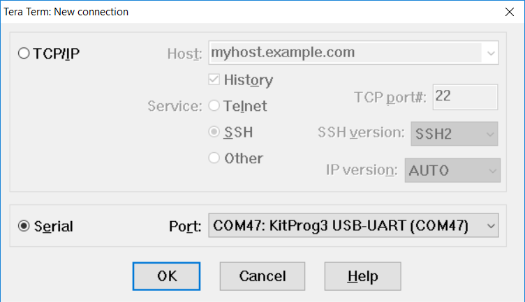
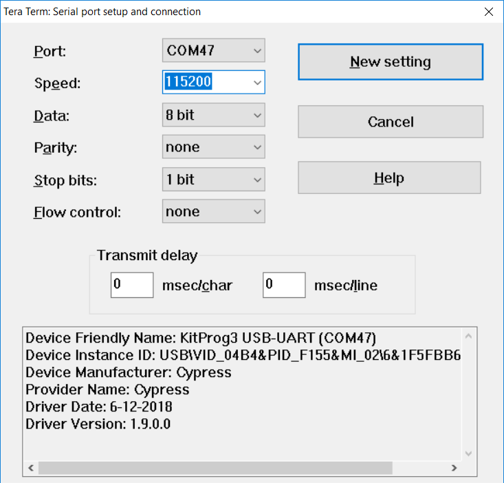
Select the serial port
Launch Tera Term and select the USB-UART COM port as shown in
Figure 29
. Note that your COM port number may be different.
Figure 29.
Selecting the KitProg3 COM port in Tera Term
Set the baud rate
Go to Setup > Serial port. Set the baud rate to 115200.
Figure 30.
Configuring the baud rate in Tera Term
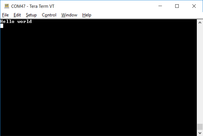
Reset the device
Press the reset switch on the (See
Table 9
)
PSOC™ 4
kit. A "Hello world" message appears on the terminal. The user LED on the kit will start blinking.
Table 9.
Pin mapping table across PSOC™ 4 kits for reset switch
Function
CY8CKIT-145(PSOC™ 4000S)
CY8CKIT-149(PSOC™ 4100S Plus)
CY8CKIT-041S-MAX(PSOC™ 4100S Max)
CY8CKIT-040T PSOC™ 4000T CAPSENSE™ Evaluation Kit
CY8CPROTO-040T
PSOC™ 4
000T CAPSENSE™ Prototyping Kit
CY8CPROTO-040T-MS
PSOC™ 4
000T Multi-Sense Prototyping Kit
CY8CPROTO-041TP CAPSENSE™ Prototyping Kit
RESET
SW1
SW2
SW1
SW1
SW1
SW1
SW1
Figure 31.
UART message printed from
PSOC™ 4
My first
PSOC 4 design using PSOC Creator
This section:
Demonstrates how PSOC™ can be programmed to do more than a traditional MCU
Shows how to build a simple PSOC™ design and install it in a development kit.
Provides detailed steps that make it easy to learn PSOC™ design techniques and how to use PSOC™ Creator.
Before you begin
Have you installed PSOC Creator?
Download and install PSOC™ Creator from the
PSOC™ Creator
home page. Note that the installation of the toolset may take a long time – see the PSOC™ Creator Release Notes for more information.
Do you have a development kit or prototyping kit?
Testing this design requires one of the kits listed in
Table 10
, which has an integrated programmer.
Kit name | Kit type | Supported device family | Part number |
|---|---|---|---|
Pioneer kit | PSOC™ 4000 | CY8C4014LQI-422 | |
CY8CKIT-042 | Pioneer kit | PSOC™ 4200 | CY8C4245AXI-483 |
Pioneer kit | PSOC™ 4200M | CY8C4247AZI-M485 | |
Pioneer kit | PSOC™ 4200L | CY8C4248BZI-L489 | |
Pioneer kit | PSOC™ 4200 Bluetooth® LE | CY8C4247LQI-BL483 | |
Pioneer kit | PSOC™ 4500S | CY8C4548AZI-S485 | |
Prototyping kit | PSOC™ 4200M | CY8C4247AZI-M485 | |
Prototyping kit | PSOC™ 4000S | CY8C4045AZI-S413 | |
Prototyping kit | PSOC™ 4100PS | CY8C4145LQI-PS433 | |
Prototyping kit | PSOC™ 4100S Plus | CY8C4147AZI-S475 |
Want to see the project in action?
About the design
This design simply blinks two LEDs using a TCPWM Component, as shown in
Figure 32
. The TCPWM is configured in PWM mode. The two complementary outputs of this PWM control the LEDs. The PWM operates at a very low frequency and 50 percent duty cycle so that the toggling of the LEDs is visible. If you use a dual-color LED instead of two separate LEDs, this project can toggle the color of the dual-color LED.
Figure 32.
My first
PSOC™ 4
design
Part 1: Create the design
This section takes you on a step-by-step guided tour of the design process. It starts with creating an empty project and guides you through hardware and firmware design entry.
Start PSOC™ Creator, and from the
File
menu choose
, as shown in
Figure 33
.
Figure 33.
Creating a new project
Select your development kit in the pop-up window. For example, if you have a CY8CKIT-149, select
Kit: CY8CKIT-149 (PSOC™ 4100S Plus)
and click
Next
. If you do not see your
PSOC™ 4
development kit listed in the menu, download and install the kit setup for your kit from the website.
Alternately, you can also select the target device radio button instead of the target hardware and select the appropriate device and click
Next
.
Figure 34.
Create a new empty
PSOC™ 4
project
Select the option
Empty Schematic
from the next window and click
Next
.
Figure 35.
Select empty schematic
Provide a project name (for example, "My_First_Project") and Workspace Name as shown in
Figure 36
. Choose an appropriate location for your new project, and click
Finish
.
Figure 36.
Selecting project name and location
Creating a new project generates a project folder with a baseline set of files shown in the
Workspace Explorer
(see
Figure 37
). To open the project schematic file, double-click
TopDesign.cysch
.
Figure 37.
Opening TopDesign schematic
Drag one PWM (TCPWM mode) Component from the Component Catalog onto the schematic, as shown in
Figure 38
.
Figure 38.
Location of the PWM Component
Double-click the PWM Component on the schematic to configure the Component properties, as shown in
Figure 39
. Click the
PWM
tab, and set the
Period
value to 254 and the
Compare
value to 127 to generate a PWM signal with a 50 percent duty cycle.
Set the
Prescaler
to 8x, to divide the input clock frequency by 8.
Figure 39.
Configuring the PWM Component
A PWM Component requires an input clock for its operation. Drag and drop a
Clock
Component onto the schematic, and configure the
Frequency
to 800 Hz by double-clicking on the Component, as shown in
Figure 40
and
Figure 41
. Because the Prescaler value set in PWM Component is 8, the effective input clock of the PWM is only 100 Hz. Therefore, the PWM period of 254 results in a PWM output time period of 2.54 seconds.
Figure 40.
Location of the clock Component
Figure 41.
Configuring the clock Component
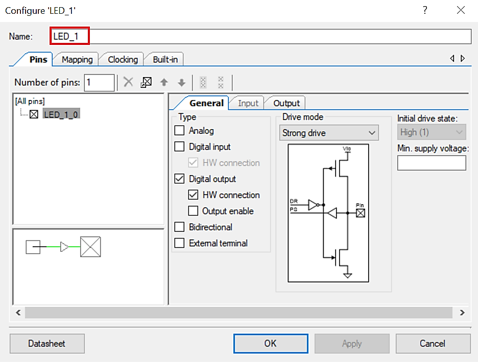
Drag and drop a
Digital Output Pin
Component. Change the name to LED_1 as shown in
Figure 42
and
Figure 43
. Add another Digital Output Pin Component and change its name to LED_2.
Figure 42.
Location of the digital output pin Component
Figure 43.
Renaming a pin Component
In the schematic window, select the wire tool as shown in
Figure 44
, or press
W
.
Figure 44.
Selecting the wire tool

Wire the Components together, as shown in
Figure 45
.
Figure 45.
Wiring the schematic
Most Components are disabled at device reset (the major exception being the Clock Component, which is automatically started as a default), and you must add code to the project to enable them. Open main.c from Workspace Explorer and add code to the main() function, as provided in Code Listing 3.
Code Listing 3 Enabling the PWM Component
 int main(void)
{
  /* Enable and start the PWM */
  PWM_1_Start();

  for(;;)
  {

  }
}
Select Build My_First_Project from the Build menu. Note that PSOC™ Creator automatically generates source code files in the Workspace Explorer window for the PWM, Clock, and Digital Output Pin Components, as shown in
Figure 46
.
Figure 46.
Generated source files
Open the file
My_First_Project.cydwr
(Design-Wide Resource file) from
Workspace Explorer
and click the
Pins
tab. You can use this tab to select the device pins for the outputs LED_1 and LED_2.
shows the pin configuration to connect the LED_1 and LED_2 pins to the LEDs in the
CY8CKIT-149 PSOC™ 4 prototyping kit
. See
Table 11
if you are using a different
PSOC™ 4
pioneer kit, or
Table 12
if you are using a
PSOC™ 4
prototyping kit.
Figure 47.
Pin selection
Table 11.
Pin mapping table across pioneer kits
Function
CY8CKIT-040 (
PSOC™ 4
CY8CKIT-041(
PSOC™ 4
100S)
CY8CKIT-042(
PSOC™ 4
CY8CKIT-042-BLE(
PSOC™ 4
200 BLE)
CY8CKIT-044(
PSOC™ 4
200M)
CY8CKIT-046(
PSOC™ 4
200L)
CY8CKIT-045S(
PSOC™ 4
500S)
Green LED (Active LOW)
P1[1]
P2[6]
P0[2]
P3[6]
P2[6]
P5[3]
P0[0]
Red LED (Active LOW)
P3[2]
9
P3[4]
10
P1[6]
P2[6]
P0[6]
P5[2]
P1[6]
Table 12.
Pin mapping table across prototyping kits
Function
CY8CKIT-145 (
PSOC™ 4
000S)
CY8CKIT-149 (
PSOC™ 4
100S Plus)
Green LED - LED 1 (Active LOW)
P3[4]
P1[6]
Green LED - LED 2 (Active LOW)
P3[5]
P5[7]
Finally, rebuild the project as explained in
Step 13
.
9
PSOC™ 4000 parts have fixed pins for complementary PWM outputs – P1[1] and P1[6]. You cannot use any other pins for PWM outputs. See the device datasheet for more details. If you are using the
CY8CKIT-040
, you can use the green LED connected to P1[1], as LED1. To use the red LED as LED2, connect P3[2] from header J4 to P1[6] from header J3, using a wire. Alternately, you can connect an external LED to P1[6] as LED2.
10
Similar to the note above, if you are using the
CY8CKIT-041
, you can use the green LED connected to P2[6], as LED1 and the complementary PWM output P2[7] for LED2. To use the red LED as LED2, connect P3[4] from header J2 to P2[7] from header J3, using a wire. Alternately, you can connect an external LED to P2[7] as LED2.
Part 2: Program the device
This section explains how to program the device. Connect the kit board to your computer using the USB cable.
Select the PSOC™ Creator menu item
, as shown in
Figure 48
.
Figure 48.
Selecting debug target
In the
Select Debug Target
dialog box, click
Port Acquire
, and then click
Connect
, as shown in
Figure 49
. Click
OK
to close the dialog box.
Figure 49.
Connecting to a device
Choose the menu item
to program the device with the project, as shown in
Figure 50
.
Figure 50.
Programming the device
You can view the programming status on the status bar (lower-left corner of the window), as shown in
Figure 51
.
Figure 51.
Programming status
After the device is programmed, ensure that the LEDs toggle, and confirm the working operation of the project.
9
PSOC™ 4000 parts have fixed pins for complementary PWM outputs – P1[1] and P1[6]. You cannot use any other pins for PWM outputs. See the device datasheet for more details. If you are using the
CY8CKIT-040
, you can use the green LED connected to P1[1], as LED1. To use the red LED as LED2, connect P3[2] from header J4 to P1[6] from header J3, using a wire. Alternately, you can connect an external LED to P1[6] as LED2.
10
Similar to the note above, if you are using the
CY8CKIT-041
, you can use the green LED connected to P2[6], as LED1 and the complementary PWM output P2[7] for LED2. To use the red LED as LED2, connect P3[4] from header J2 to P2[7] from header J3, using a wire. Alternately, you can connect an external LED to P2[7] as LED2.
Summary
This application note explored the
PSOC™ 4
architecture and development tools.
PSOC™ 4
is a truly programmable embedded system-on-chip, integrating configurable analog and digital peripheral functions, memory, and an Arm® Cortex®-M0/M0+ microcontroller on a single chip. Because of the integrated features and low-leakage power modes,
PSOC™ 4
is an ideal choice for low-power and cost-effective embedded systems.
This application note also guided you to a comprehensive collection of resources to accelerate in-depth learning about
PSOC™ 4
.
References
Infineon Technologies AG:
001-54181: Getting started with PSOC™ 3
;
Available online
Infineon Technologies AG:
001-77759: Getting started with PSOC™ 5LP
;
Available online
Revision history
Document revision | Date | Description of changes |
|---|---|---|
** | 2013-01-24 | New Application Note |
*A | 2013-04-11 | Demo project changed to leverage Pioneer kit. Added architecture introduction. |
*B | 2013-05-09 | Reformatted graphics. Updated links. |
*C | 2013-12-19 | Updated attached Associated Project files. Updated content across the entire document. Updated in new template. |
*G | 2014-04-10 | Updated the projects and the respective section in the AN to support PSOC™ Creator 3.0 SP1 and PSOC™ 4000 device. |
*H | 2014-09-25 | Added Code Examples section. Minor edits and format changes throughout the document. |
*I | 2015-03-17 | Added More Information section. Removed detailed feature descriptions. Updated for PSOC™ 4200M family of devices. |
*J | 2015-09-10 | Added the following sections: Convert Project to Bootloadable for CY8CKIT-049, Bootload Your CY8CKIT-049, and More PSOC™ 4 Code Examples. Updated Figure 8 . |
*K | 2015-09-16 | Updated for PSOC™ 4200L. Updated the example projects to PSOC™ Creator 3.3. |
*L | 2015-12-30 | Updated the example projects to PSOC™ Creator 3.3 SP1. |
*M | 2016-02-05 | Updated for PSOC™ 4000S and PSOC™ 4100S. Updated the example projects to PSOC™ Creator 3.3 SP2. Updated Table 10 , Table 11 to add PSOC™ 4200 BLE. |
*N | 2017-04-19 | Updated logo and copyright |
*O | 2017-10-06 | Added references to PSOC™ 4100S Plus throughout the document. Updated Table 1 to add PSOC™ 4100S Plus. |
*P | 2017-11-03 | Updated the example projects to PSOC™ Creator 4.2 Updated Table 1 to add supported kit Updated Table 10 to add CY8CKIT-49, CY8CKIT-145 and CY8CKIT-149 Added Table 11 to include CY8CKIT-145 and CY8CKIT-149 pin mapping Updated Figure 7. Added example project of CY8CKIT-145 and CY8CKIT-149 as a part of the AN79953.zip file in this application note landing page. |
*Q | 2018-03-06 | Updated template Updated for PSOC™ 4100PS Minor edits and format changes throughout the document Added example project of CY8CKIT-147 as a part of the AN79953.zip file |
*R | 2018-05-04 | Updated template Corrected the link to PSOC™ 4100S Plus in PSOC™ resources |
*S | 2019-09-06 | Updated Table 1 to add PSOC™ 4500 and update the specifications of PSOC™ 4100S Plus device family. Added Motor Control Accelerator feature. |
*T | 2020-11-09 | Updated for ModusToolbox™ support for some of the PSOC™ 4 devices. PSOC™ 4 families are recategorized in Local sales office locations PSOC™ 4 feature set Added new section My first PSOC™ 4 design using ModusToolbox™ Removed sections : Convert Project to Bootloadable for CY8CKIT-049, Bootload Your CY8CKIT-049, and More PSOC™ 4 Code Examples |
*U | 2021-07-08 | Updated to Infineon template Updated Figure 2, Figure 3, Figure 4, and Figure 5 to the latest MTB 2.3 version Updated document with PSOC™ 4100S Max device Changed the default device to PSOC™ 4100S Max and updated Figure 8 Updated Modify the design section |
*V | 2022-06-15 | Updated document with PSOC™ 4000T device Updated with the latest release version of ModusToolbox™ (version-3.0) |
*W | 2023-02-13 | Updated Folder structure with the latest release version of ModusToolbox™(VERSION-3.0) |
*X | 2023-07-21 | Updated the pin changes for PSOC™ 4000T device Updated content with the latest release of ModusToolbox™ 3.1 |
*Y | 2024-02-05 | Fixed broken links |
*Z | 2024-02-26 | Updated content with the latest release of ModusToolbox™ 3.2 |
AA | 2024-09-18 | Changed the default device to CY8CPROTO-040T kit |
AB | 2025-01-13 | Updated the document with CY8CPROTO-040T-MS PSOC™ 4000T Multi-Sense Prototyping Kit |
AC | 2025-03-27 | Updated document with PSOC™ 4100T Plus device |
Trademarks
The Bluetooth® word mark and logos are registered trademarks owned by Bluetooth SIG, Inc., and any use of such marks by Infineon is under license.
PSOC™, formerly known as PSoC™, is a trademark of Infineon Technologies. Any references to PSoC™ in this document or others shall be deemed to refer to PSOC™.
3
IDACs are available only when CAPSENSE™ is not in use. See the respective PSOC™ 4 architecture TRM for more details.
5
IDACs are available only when CAPSENSE™ is not in use. See the respective PSOC™ 4 architecture TRM more details.
7
IDACs are available only when CAPSENSE™ is not in use. See the respective PSOC™ 4 architecture TRM for more details.
8
IDACs are available only when CAPSENSE™ is not in use. See the respective PSOC™ 4 architecture TRM for more details.
9
PSOC™ 4000 parts have fixed pins for complementary PWM outputs – P1[1] and P1[6]. You cannot use any other pins for PWM outputs. See the device datasheet for more details. If you are using the
CY8CKIT-040
, you can use the green LED connected to P1[1], as LED1. To use the red LED as LED2, connect P3[2] from header J4 to P1[6] from header J3, using a wire. Alternately, you can connect an external LED to P1[6] as LED2.
10
Similar to the note above, if you are using the
CY8CKIT-041
, you can use the green LED connected to P2[6], as LED1 and the complementary PWM output P2[7] for LED2. To use the red LED as LED2, connect P3[4] from header J2 to P2[7] from header J3, using a wire. Alternately, you can connect an external LED to P2[7] as LED2.