AN92239 Proximity sensing with CAPSENSE
About this document
Scope and purpose
This document provides a comprehensive technical guide for designing and implementing proximity-sensing solutions using the CAPSENSE™ technology from Infineon.
Intended audience
The intended audience for this document is primarily developers, engineers, and designers who are interested in implementing proximity sensing solutions using Infineon’s CAPSENSE™ technology.
Note:
The document assumes a basic understanding of Infineon’s CAPSENSE™ technology, electronics, and electrical engineering principles as well as software development and programming experience. If you are new to CAPSENSE™ and PSOC™ architecture offered by Infineon, see the
References
section to get familiar with these offerings.
Abbreviations
Abbreviation | Description |
|---|---|
ADC | Analog-to-Digital Converter |
CMOD | Modulator Capacitor |
CP | Parasitic Capacitance |
CSD | Self-Capacitance Sensing |
CSH | Shield Tank Capacitor |
CSX | Mutual-Capacitance Sensing |
EMC | Electromagnetic Compatibility |
ESD | Electrostatic Discharge |
GND | Ground |
GPIO | General-Purpose Input/Output |
HID | Human Interface Device |
HMI | Human machine interface |
IDAC | Current-Output Digital-to-Analog Converter |
IDE | Integrated Development Environment |
IIR | Infinite Impulse Response (filter) |
MCU | Micro Controller Unit |
MSCLP | Multi Scan Converter version 3 – Low Power |
PSOC™ | Programmable System on Chip controllers offered by Infineon |
SNR | Signal-to-Noise Ratio |
VREF | Programmable reference voltage blocks available inside PSOC™ used for CAPSENSE™ and ADC operation |
Introduction
Proximity sensors allow users to interact with electronic devices and enable devices to detect the presence of nearby objects without physical contact, which makes them ideal for applications such as touchless controls, gesture control, object detection, and proximity switches.
Proximity sensing can be implemented using various technologies, such as capacitive, inductive, magnetic, Hall effect, optical, ultrasonic sensors, and radar, each of which has its own advantages and disadvantages.
Capacitive proximity sensing is widely adopted as it enables robust designs with low cost, high reliability, low power, sleek aesthetics, and seamless integration with existing user interfaces. Infineon’s CAPSENSE™ devices provide robust proximity-sensing capabilities based on self-capacitance capable of a 30 cm proximity-sensing distance.
This application note describes:
Technology behind capacitive proximity sensing
Design of proximity sensor using Infineon’s CAPSENSE™ devices
Sensor layout guidelines for robust and reliable proximity sensing solution
Firmware libraries and resources offered by Infineon to implement proximity-sensing solutions.
Tuning guidelines of hardware and firmware parameters to achieve large proximity-sensing distances and liquid tolerance.
Guidelines for implementation of proximity-based gesture detection
Troubleshooting tips and techniques
Proximity presence detection
Proximity sensing is the process of detecting the presence of a nearby object without any physical contact. Capacitive proximity sensing technique based on CAPSENSE™ detects the presence of an (electrically conductive) object by measuring the change in the capacitance of the sensor, which typically is in the range of a few femtofarads (fF). The sensor could be a length of wire or a copper pad on PCB, the design is explained in detail in subsequent sections of this document.
Gesture detection
Gesture detection is the technique of interpreting (human body) movements and providing gesture-type information to the device. Gesture-based user interfaces provide an intuitive way to interact with the system. This improves the user experience in applications such as 3D control of global maps on a computer screen. Proximity sensors can also detect gestures, such as left-to-right or right-to-left swipes without any contact. Proximity sensors based on CAPSENSE™ can be used to detect gestures without any physical contact between the user and the device.
Applications
CAPSENSE™ is one of the popular human-machine interface technologies, CAPSENSE™-based capacitive proximity sensing is widely used in a variety of applications such as:
Wake-on-approach feature in battery-powered applications:
Smart locks
Wireless mouse, computer keyboards
Gesture detection in a human-machine interface (HMI):
3D control computer interface
Toys
Musical Instruments (e.g., Theremin)
Presence and approach detection:
Hearables, wearables such as smart watches, AR/VR glasses, headsets
Specific absorption rate (SAR) regulation in tablets and mobile phones
Smart home
Smart speaker, door locks, wall switches, smart lights, home decor, rangehood, cooktops, backlight control in control panels
Climate and convenience
Faucets, garbage bins, toilet, smart compost, thermostat (gesture control), toothbrush (turn on light on approach), soap dispenser, towel dispensers, automatic door openers, etc.
Introduction to CAPSENSE
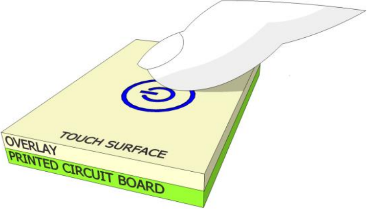
Infineon’s CAPSENSE™ controllers use capacitive sensing where changes in capacitance because of the presence of a finger on or near a sensor surface, are detected. Typically, capacitive sensors are circular metal-fill areas itched on a PCB.
Figure 1
illustrates an example of the capacitive sensor button. The sensing functionality is achieved using a combination of hardware and firmware.
Figure 1.
Illustration of a capacitive sensor
A capacitive sensor can be designed using two different techniques: self-capacitance or mutual capacitance as shown in
Figure 2
.
Figure 2.
Self and mutual capacitance-based touch sensing working principle
PSOC™ devices use sensing methods known as capacitive sigma-delta (CSD) for self-capacitance sensing and CAPSENSE™ Crosspoint (CSX) for mutual-capacitance sensing. The CSD and CSX touch sensing methods provide the industry’s best-in-class Signal-to-Noise ratio (SNR).
Self-capacitance
Self-capacitance uses a single pin and measures the capacitance between the pin and nearby ground. In a CAPSENSE™ self-capacitance system, the sensor capacitance measured by the controller is called C
S
.
When a finger is not near the sensor:
Sensor capacitance (C S ) = Parasitic capacitance (C P ) of the
system
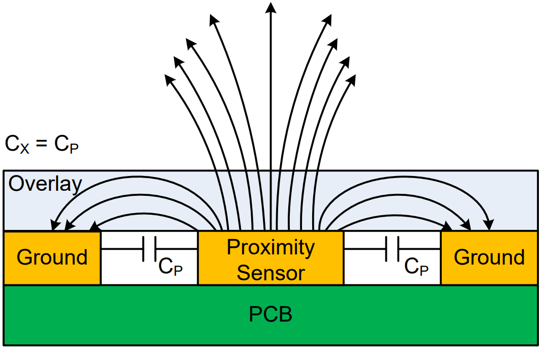
The parasitic capacitance, CP is a simplification of the distributed capacitance that includes the effects of the sensor pad, the overlay, the trace between the CAPSENSE™ controller pin and the sensor pad, the vias through the circuit board, and the pin capacitance of the CAPSENSE™ controller. CP is related to the electric field around the sensor pad. Although
Figure 3
shows field lines only around the sensor pad, the actual electric field is more complicated.
Figure 3.
Illustration of sensor parasitic capacitance and electric field
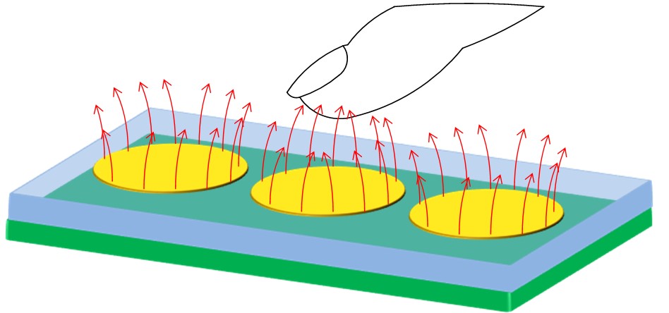
When an object, such as a finger approaches the sensor, some of the electric field lines couples to the target object and add a small amount of finger capacitance (C
F
) to the existing C
P
, as shown in
Figure 4
. This change in capacitance is measured by the CAPSENSE™ circuitry to detect the proximity of the target object.
Figure 4.
Illustration of electric field lines coupling to finger
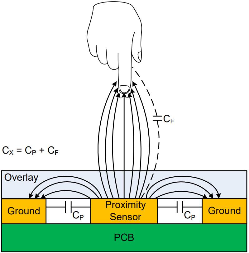
When a finger is near the sensor:
Sensor capacitance (C S ) = Parasitic capacitance (C P ) + Finger
capacitance (C F )
The change in total sensor capacitance (C
S
) due to addition of finger capacitance (C
F
) is measured to determine user interaction with the system.
CAPSENSE system
Infineon’s PSOC™ devices use CAPSENSE™ system for self-capacitance sensing as shown in
Figure 5
. It operates by charging the sensor capacitance connected to a PSOC™ pin and measuring the capacitance. A capacitance-to-digital converter then converts it into a digital value that is proportional to the self-capacitance between the electrodes, known as “raw count”.
Figure 5.
Simplified CSD modulator
Raw count and sensor capacitance relationship in CAPSENSE™ is:
Raw count = G C C S
where,
G
C
is the capacitance to digital conversion gain
C
S
is the self-capacitance of the electrode
shows a plot of raw count over time. When a finger approaches the sensor, the Sensor Capacitance (C
S
) increases from C
P
to C P+ CF, and the raw count increases. By comparing the change in the raw count to a predetermined threshold, firmware logic decides whether the sensor is active (target object is present).
Figure 6.
Raw count vs. time

Mutual capacitance
Mutual-capacitance sensing measures the capacitance created by electrical coupling between two nearby electrodes, one of which is called the transmit (Tx) electrode, and another electrode is called the receive (Rx) electrode. In a mutual-capacitance measurement system, a digital voltage (signal switching between V
DD
and GND) is applied to the Tx pin, and the amount of charge received on the Rx electrode is measured. The amount of charge received on the Rx electrode is directly proportional to the mutual capacitance (C
M
) between the two electrodes.
When a finger is placed between the Tx and Rx electrodes, the mutual capacitance (C
M
) decreases because of the obstruction of the field by the finger, and the grounding effect of the finger as shown in
Figure 2
. The CAPSENSE™ system measures the change in charge received on the Rx electrode to detect the touch/no touch condition.
This application note aims to describe the design of a proximity-sensing solution using the self-capacitance technique, therefore, the details of mutual capacitance provided here are limited. See
AN85951 – PSOC™ 4 and PSOC™ 6 MCU CAPSENSE™ design guide
for more information on mutual capacitance-based touch sensing solutions.
Designing a CAPSENSE proximity-sensing solutions
Similar to any other product, certain requirement specifications need to be defined to design a proximity-sensing solution. The specifications for proximity-sensing design can be listed as follows:
Maximum sensing distance required
Behavior in the presence of liquid
Operation in extreme operational environmental conditions
Operation in areas with high EMI noise
illustrates the typical flow of a CAPSENSE™ solution design. This flow is similar to any other electronic product design flow except that CAPSENSE™ designs involve an additional step called “Tuning”.
Figure 7.
Recommended CAPSENSE™ design flow
Terminology
defines CAPSENSE™ related terms that are used throughout the document:
Terms | Description |
|---|---|
Detection distance | Detection distance is the distance where the added capacitance exceeds some threshold values. The detection distance depends on the sensor’s electrical field propagation (electrical field strength). A longer propagation distance provides a longer detection range. |
Target object | Object of which presence or movement is to be detected by proximity sensing design, e.g., Human hand/finger, conductive objects. |
Widget | CAPSENSE™ widgets are a combination of one or more CAPSENSE™ sensors, which as a unit represent a certain type of user interface, such as sliders or trackpads. Widgets are broadly classified into four categories:
|
Channel | Each instance of the CAPSENSE™ peripheral in the PSOC™ MCU device is considered as a channel and multiple instances imply multiple channels. |
Raw count | As mentioned earlier, sensor capacitance is converted into a count value by the CAPSENSE™ hardware. The converted digital count value is referred to as the raw count. Processing of the raw count results in ON/OFF states for the sensor. |
Baseline | A value resulting from a firmware algorithm that estimates a trend in the raw count when there is no conductive object/human finger present on the sensor. The baseline is less sensitive to sudden changes in the raw count and provides a reference point for computing the difference count. |
Baseline reset | Event at which the baseline (raw count) value is set to a new value. Baseline is the value recalculated based on the current raw count when the raw count is within noise thresholds. |
Difference count or signal | Subtracting the baseline level from the raw count produces the difference count that is used in the decision process. The thresholds are offset by a constant amount from the baseline level. |
LP-AoS mode | Low Power-Always-on-Sensing mode of the devices with fifth-generation CAPSENSE™. Devices in LP-AoS mode are capable of scanning and processing a widget while in Deep Sleep mode. This feature wakes up the device on a touch detection or on a timeout. |
Parasitic capacitance, CP | The parasitic capacitance, CP is a simplification of the distributed capacitance that includes the effects of the sensor pad, the overlay, the trace between the CAPSENSE™ controller pin and the sensor pad, the vias through the circuit board, and the pin capacitance of the CAPSENSE™ controller. |
Scan slot | A scan slot represents a group of sensors scanned together. In single-channel mode, one sensor is scanned per scanning slot. |
Signal-to-noise ratio (SNR) | As the name suggests it is the measure of the quality of the information in a signal to noise present in the signal. In a capacitive proximity sensing system, SNR implies reliable and accurate detection. |
Shield (shield electrode) | When any of the copper areas on the PCB, like hatch fill around the sensor (as shown in Figure 14) is connected to the driven shield signal, it is referred to as a shield electrode. |
Challenges
While designing robust and reliable real-world applications of capacitive proximity sensing, several challenges need to be considered. This application note attempts to address most of the significant challenges as follows:
Low power
Low-power embedded design is motivated by the need to run battery-powered applications for as long as possible while consuming minimum power and not requiring frequent battery charging. Furthermore, low power implies a lower cost of operation and a smaller battery size.
This section describes a few of the recommended techniques that can be used to reduce power consumption in CAPSENSE™ proximity sensing design:
Use of low-power MCU
The simplest way to reduce power consumption is to use a device that consumes very low power while operating.
See the
CAPSENSE™ controllers
page on the Infineon website to select a device that meets the design requirements with the least possible operating current.
Infineon’s PSOC™ 4000T with fifth-generation CAPSENSE™ MSCLP is the lowest power MCU featuring always-on capacitive sensing in Deep Sleep mode. Up to a 10x reduction in power consumption in low-power mode and 5x reduction in power consumption in active mode, PSOC™ 4000T is recommended for low-power designs.
Use of Low Power modes with wake-on-approach
One of the ways to reduce power consumption is to implement Low Power modes on the MCU and operate in normal/active mode only when required, such as Wake-on-Approach. This technique can be implemented using
Low-power widgets
offered by fifth-generation CAPSENSE™ MSCLP devices. See the
Wake-on-approach
section for more details.
Reducing scan times when MCU is active, reduces the total time device spends keeping the CPU active, therefore, reducing power consumption. Scan time can be reduced with the following techniques:
Increasing (CAPSENSE™) modulator clock frequency
Reducing scan resolution
See the
Tuning the proximity-sensing design
section for more details on how to tune these parameters for lowering power consumption.
Another technique to save power is Implementing the Wake-on-Approach using Sensor Ganging, which refers to scanning all the capacitive sensors as a single proximity sensor. See the
Sensor ganging
section for more details.
Turning off part of the circuit
One of the techniques to reduce the power consumption in a product is to turn off part of the circuit when not required. Note that such a technique requires the circuit to be designed in such a way that part of the circuit can be disabled by the firmware.
Relevant resources
Refer to the following resources for more information on reducing power consumption in CAPSENSE™-based design solutions:
Application notes:
AN234231
- Achieving lowest-power capacitive sensing with PSOC™ 4000T
AN85951
- PSOC™ 4 MCU low-power modes and power reduction techniques
Code examples:
Large proximity-sensing distance
Achieving a large proximity-sensing distance in an end system is a challenge because the proximity-sensing distance depends on multiple and interdependent factors.
describes hardware, software, and system parameters that affect proximity-sensing distance.
Parameter | Effect | How to improve/Best Practices |
|---|---|---|
Type and size of the sensor | Proximity-sensing distance is directly proportional to the area of the sensor. However, the increase in the surface area of the sensor also increases CP which has an adverse effect on sensing distance. | Use loop (or ring) sensors of the maximum size possible instead of solid fill patterns. See the Layout guidelines section for more details. |
Parasitic capacitance (CP) of the sensor | Proximity-sensing distance increases with an increase in the CF/CP ratio. | Design the sensor such that CP can be minimized while keeping the large sensing area. See the Layout guidelines section for more details. |
Nearby floating or grounded conductive objects | Conductive objects can absorb a part of the electrical field and decrease the propagation distance, and therefore, the detection range. |
|
Scan resolution of the sensor | Higher the resolution, the higher the sensitivity and therefore, the sensing distance. | Set Number of sub conversions (N SUB ) to change the resolution of scans, higher the N SUB , higher the power consumption. See the Tuning guidelines for details. |
Nearby electrical noise sources | Electrical noise interfering with the proximity sensor electric field results in reduced SNR and therefore, reduced proximity-sensing distance. |
|
Devices with CAPSENSE™ MSCLP are recommended for new designs requiring large proximity sensing distances. It provides improved sensitivity based on the all-new ratio-metric analog architecture and advanced hardware filtering.
Liquid tolerance
Proximity sensors are used in applications such as faucets and soap dispensers. These applications require a robust operation even in the presence of water droplets and other liquids which can cause false triggers.
Making the design liquid-tolerant requires various considerations at every stage of the design i.e., layout, firmware, and tuning. Recommended strategies to make the CAPSENSE™ design liquid-tolerant are:
Effective use of shield electrode
Use of guard sensor
Tuning for liquid tolerance
See the
Layout guidelines for liquid tolerance
,
Firmware guidelines for liquid tolerance
, and
Tuning for liquid tolerance
for more details.
Relevant resources
Following code examples demonstrate how to achieve Liquid Tolerance in CAPSENSE™ based design:
High sensing reliability/noise tolerance
Proximity sensors are susceptible to noise because of their large sensor area and high sensitivity setting. High noise makes it difficult to achieve a good signal-to-noise ratio (SNR) (typically greater than 5:1), which is required for reliable proximity sensing.
lists the common sources that contribute to noise in proximity sensing and respective recommended mitigation techniques.
Noise source | Examples | Recommended noise mitigation technique |
|---|---|---|
PWM driven devices | LEDs, motors | Design to keep these sources as far as possible from the sensor. Add a ground hatch between these devices and sensors. |
Switching power converter | AC-DC, DC-DC, DC-AC | |
High-speed communication interfaces | USB, Ethernet | Use shielded twisted pair wires, design to keep these sources as far as possible from the sensor. Add a ground hatch between these devices and sensors. |
AC supply lines | Relays and switches | Use shielded twisted pair wires when power lines are passing near the sensors. |
Use of filters
The most effective method of reducing noise in CAPSENSE™-based design is to use filters. Filters help to reduce the noise in raw count significantly and improve the SNR, and sensing accuracy. Various filters offered by the CAPSENSE™ ecosystem are explained in the Filters section.
and PSOC™ 4100T Plus devices with fifth-generation CAPSENSE™ provide improved SNR based on the all-new ratio-metric analog architecture and advanced hardware filtering to enable reliable and robust capacitive proximity sensing.
Directionality
A proximity sensor can detect objects from all directions within a certain range. Implementing directional proximity sensing in an end system poses a significant challenge as it relies on multiple factors such as overall enclosure design, hardware components, and PCB layout.
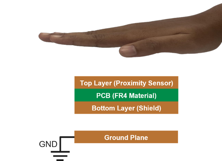
To achieve directional sensitivity in proximity sensors, place a ground plane at the bottom of the sensor as shown in
Figure 8
. If the ground plane is too close to the sensor, sensitivity will be very low as it absorbs most of the electric field lines generated by the sensor. This is because the ground plane provides a path for the electric field lines to terminate, reducing the strength of the field that interacts with the object being sensed. As a result, the sensor's ability to detect objects is impaired. To avoid this, the ground plane must be placed with some separation from the shield. This will allow the electric field lines to interact with the object, while the ground plane's absorption effect is minimized. As distance between ground plane and bottom layer (shield) increases, signal strength from top side increases. The optimal distance depends on various system factors and requires testing on the actual system to determine the best distance. As a rule of thumb, keep the separation between ground plane and bottom layer (shield) at least 30% of the required sensing distance.
Figure 8.
Ground plane placement for proximity directionality
Note:
Using a solid ground plane with a slight overhang from the sensor size can help achieve excellent directionality. However, it is important to note that a solid ground plane also increases the parasitic capacitance (C
p
), which varies with the distance of the ground plane, which results in lower sensitivity.
Resource to get started on CAPSENSE proximity-sensing
This section describes the resource offered by Infineon to get started on designing CAPSENSE™ proximity-sensing solutions.
Online resources
Getting started kits
CY8CKIT-040T PSOC™ 4000T CAPSENSE™ Evaluation Kit
Figure 9.
CY8CKIT-040T PSOC™ 4000T CAPSENSE™ Evaluation Kit
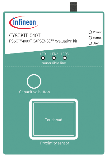
CY8CKIT-040T PSOC™ 4000T CAPSENSE™ Evaluation Kit
demonstrates the following key capabilities of the fifth-generation CAPSENSE™ technology available in the PSOC™ 4000T series MCU :
Superior touch and proximity-sensing performance
Ultra-low-power capability based on “Always-On” sensing
Superior liquid tolerance
CAPSENSE™ proximity shield
Figure 10.
CY8CKIT-024 with CAPSENSE™ proximity shield
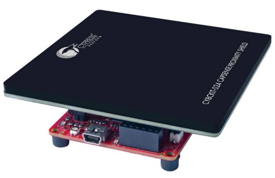
This Arduino-compatible
CY8CKIT-024 with CAPSENSE™ proximity shield
demonstrates the proximity-sensing capabilities of the CAPSENSE™ technology in PSOC™ products. It can be used with the PSOC™ Pioneer Kits such as
CY8CKIT-042 PSOC™ 4 Pioneer Kit
or the
CY8CKIT-040 PSOC™ 4000 Pioneer Kit
.
Code examples
This code example demonstrates an implementation of a low-power proximity sensing application using CY8CKIT-040T PSOC™ 4000T CAPSENSE™ Evaluation Kit to detect a target object (a hand) at large distance.
It includes recommended power states, transitions, adjustments for tuning parameters, and the method of tuning. This example uses a MSCLP low-power widget to demonstrate different considerations to implement a low-power design.
This code example also explains how to manually tune the low-power widget for optimum performance and largest distance with respect to parameters such as power consumption and response time using the CSD-RM sensing technique and CAPSENSE™ Tuner.
This code example demonstrates an implementation of a low-power proximity sensing with liquid tolerance using CY8CKIT-040T PSOC™ 4000T CAPSENSE™ Evaluation Kit.
Layout guidelines
The sensor layout plays a crucial role in achieving the required proximity-sensing distance and reliability of the detection. A capacitive proximity sensor can be constructed in various shapes, sizes, and using different materials depending on the application requirement. The basic objective during sensor layout design is to:
Achieve high sensitivity
Reliable detection
Maximum proximity-sensing distance
Minimum CP
Though the fundamental principle of detection remains the same, the working of (proximity) gesture detection is different from proximity presence detection. Except for the up-down gesture (e.g., moving the hand near and far to the sensor), gesture detection requires more than one sensor. Therefore, the layout design of the sensor for proximity presence detection and gesture detection will differ and are explained in this section.
Presence detection
As described earlier, proximity presence sensing is the process of detecting the presence of nearby objects without any physical contact.
Table 5
shows the possible types of capacitive proximity sensor designs and their respective use cases:
Sensor type | Recommended use case | Sensor C P | Estimated sensing range |
|---|---|---|---|
Button sensor | When required proximity-sensing distance or area available for the sensor is very small. | High | ~Equal to the diameter of the sensor |
Ganged sensor | When no dedicated sensor pin or area is available on the PCB for implementing a proximity sensor, but capacitive touch sensors are available. | Highest | Sensing range depends on the types and number of sensors being ganged together |
PCB trace | When the required proximity-sensing distance is very large. | Optimal | ~Equal to the diameter/diagonal of the sensor 1 |
Wire-loop | When the required proximity-sensing distance is very large and not enough area is available on PCB / other design constraints preventing PCB trace type sensor. | Optimal | ~Equal to the diameter/diagonal of the sensor 1 |
Button sensor
When the sole purpose of the design is proximity sensing, button sensors are not recommended. Generally, the reason for using button sensors is design constraints where existing touch sensors are repurposed for proximity sensing.
Because of the way, the button sensor is constructed (with solid) surface area, it exhibits high C
P
, which results in lower sensing resolution and effective sensing range. Also, because the diameter of a button sensor typically ranges from 5 mm to 15 mm, the proximity-sensing distance achieved with a button sensor is limited when compared to other sensor implementation methods.
Figure 11.
Proximity sensing with button sensor
In applications that need larger distance proximity sensing than what can be achieved with a simple button sensor, a ring around the button working as a separate proximity sensor is recommended. Along with other range improvement methods, like placing a
Shield electrode
at the bottom of the sensor electrode, can provide improved sensing range.
Ganged sensor
Sensor ganging refers to connecting multiple sensors (buttons, proximity trace, proximity loop etc.) to the CAPSENSE™ circuitry and scanning them as a single sensor, generally used for the wake-on-approach technique. It is explained in detail in the
Sensor ganging
section.
PCB trace sensor
A long PCB trace on an FR4 or a Flexible Printed Circuit (FPC) board can form a proximity sensor. The trace can be a straight line (
Figure 12
(a)), or it can surround the perimeter of a system’s user interface, as shown in
Figure 12
(b). Implementing a proximity sensor with a PCB trace has the following advantages when compared to other sensor implementation methods:
Low CP
High proximity-sensing distance in case of loop sensor, as more electric field lines couple to the hand/conductive object
Suitable for mass production
Figure 12.
CAPSENSE™-based proximity sensing with PCB trace
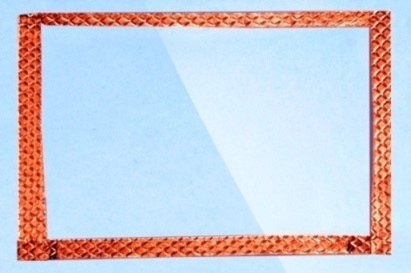
Wire sensor
A single length of wire looped back as shown in
Figure 13
, works well as a proximity sensor. Implementing a proximity sensor with a wire loop has the following advantages when compared to other sensor implementation methods:
Provides greater flexibility of where the sensor can be placed in the product, e.g., a wire loop can be mounted underneath the product casing/enclosure wall
Because of the flexibility of implementation in size, a larger proximity distance can be achieved
However, using a wire sensor is not an optimal solution for mass production because of manufacturing cost and complexity. Therefore, it is not recommended.
Figure 13.
Proximity sensor prototype using copper tape as wire loop
1
The actual sensing distance is affected by multiple factors which are discussed in Section
Large proximity-sensing distance
earlier, the sensing distance mentioned here is based on estimation.
General layout guidelines
This section describes the guidelines that apply to the construction of all types of capacitive proximity sensors. These guidelines are recommended to improve the performance of the capacitive proximity-sensing design.
Size of the sensor vs. proximity sensing distance
A larger sensor area results in more electric field lines coupling with the target object, increasing the sensor signal. Therefore, the size of the sensors increases with the required proximity-sensing distance in the design. However, a large sensor area results in a high sensor CP and potentially higher noise levels. This can adversely affects the proximity-sensing distance. Using a loop sensor of equivalent diameter/diagonal (
Figure 12
(b)) instead of solid-fill sensor results in a lower sensor CP, lower noise, and improved proximity-sensing distance.
Because of the intrinsic high sensitivity of the proximity sensors, nearby noise sources and floating or grounded conductive objects reduce the SNR and therefore, proximity-sensing distance.
As a thumb rule, it is recommended to start with a minimum loop diameter (for a circular loop) or diagonal (for a square loop) equal to the required proximity-sensing distance. If the required proximity-sensing distance cannot be achieved with a loop diameter or diagonal equal to the required proximity-sensing distance, increase the sensor size till the required proximity-sensing distance is achieved.
Parasitic capacitance of the sensor
As the C
F
indicates the change in capacitance in the presence of the target object, the proximity-sensing distance depends on the ratio of the C
F
to the C
P
because of its effect on measurement resolution. The proximity-sensing distance increases with an increase in the C
F
/C
P
ratio. For a given sensor size, the value of C
F
depends on the distance between the sensor and the target object, and the size of the target object. Though CF is not completely controllable by the design, to maximize C
F
/C
P
ratio, decreasing C
P
while keeping the sensing area covered equivalent, is the easiest approach (e.g., loop sensor).
The C
P
of the sensor can be minimized by:
Selecting an optimum sensor type
Reducing the sensor trace length
Minimizing the coupling of sensor electric field lines to the nearby ground or metal objects
To minimize the sensor trace length and, thereby, the sensor C
P
, place the CAPSENSE™ MCU device as close to the sensor as possible.
To reduce the coupling of sensor electric field lines to the ground, implement a hatch fill surrounding the sensor in the top layer and bottom layer of the PCB as explained in the following section.
Shield electrode
When the hatch fill as shown in
Figure 14
is implemented around the sensor and is driven with a signal (same as that of the sensor), it is referred to as a shield electrode. Shield electrode with hatch fill of 0.17 mm (7 mil) trace and 1.143 mm (45 mil) grid, on the top layer and the bottom layer surrounding the sensor can be used for the following purposes:
To reduce the sensor CP
Improve water tolerance
To reduce the effect of floating/grounded conductive objects on the proximity-sensing distance
To make the proximity sensing unidirectional
illustrates an example of shield design to reduce sensor CP.
Figure 14. Example of shield electrode pattern and placement
External capacitors
CAPSENSE™ devices require an external capacitor for self-capacitance sensing. These external capacitors are connected between a dedicated GPIO pin and the ground. Table 6 lists the recommended values of the external capacitors for the respective CAPSENSE™ generation.
Type | CAPSENSE™ generation | Recommended values |
|---|---|---|
C MOD | 3 rd and 4 th | 2.2 nF |
C MOD1 and C MOD2 | 5 th | 2.2 nF |
C SH_TANK | 3 rd and 4 th | 10 nF if shield electrode is implemented, NA otherwise |
For more information, see the “Schematic rule checklist” section of the
AN85951 - PSOC™ 4 and PSOC™ 6 MCU CAPSENSE™ design guide
.
Pin assignment
An effective method to reduce the interaction between proximity sensor traces and communication or non-sensor traces is to isolate each by port (pin) assignment.
Figure 15
shows a basic version of this isolation for a 32-pin QFN package. Because each function is isolated, the CAPSENSE™ controller is oriented such that there is no crossing of communication, LED, and sensing traces.
Figure 15.
Recommended: Port isolation for communication, CAPSENSE™, and LEDs
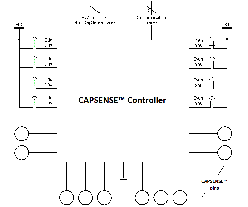
The CAPSENSE™ controller architecture imposes a restriction on the current budget for even and odd port pins. For a CAPSENSE™ controller, if the current budget of an odd port pin is 100 mA, the total current is drawn though all odd port pins must not exceed 100 mA. In addition to the total current budget limitation, there is also a maximum current limitation for each port pin. See the datasheet of the CAPSENSE™ controller used in the application for the details.
All CAPSENSE™ controllers provide high current sink and source capable port pins. When using the high current sink or source from port pins, select the ports that are closest to the device ground pin to minimize the noise.
Note:
While the CAPSENSE™ is scanning the sensor, limit the total source/sink current through GPIOs to 40 mA. Sinking/sourcing more than 40 mA during the sensor scan may result in excessive noise in the sensor raw count.
ModusToolbox™ CAPSENSE™ configurator can be used for the pin assignment in the CAPSENSE™ design as shown in
Figure 16
.
Figure 16.
PSOC™ pin assignment with ModusToolbox™ CAPSENSE™ configurator
External capacitors pin selection
lists the recommended pins for CMOD and CSH_TANK capacitors for a CAPSENSE™-based design.
Device | C MOD (or C MOD1 for fifth-generation CAPSENSE™) | C SH_TANK (or C MOD2 for fifth-generation CAPSENSE™) |
|---|---|---|
PSOC™ 4000 | P0[4] | P0[2] |
PSOC™ 4000T | P4[2] | P4[3] |
PSOC™ 4100/PSOC™ 4200 | P4[2] | P4[3] |
PSOC™ 4100T Plus | P1[0] | P1[1] |
PSOC™ 4200M/PSOC™ 4200L | CSD0: P4[2] | CSD0: P4[3] |
CSD1: P5[0] | CSD1: P5[1] | |
PSOC™ 4 Bluetooth® LE | P4[0] | P4[1] |
PSOC™ 6 MCU | P7[1] | P7[2] |
PSOC™ 4S-series, PSOC™ 4100S Plus | P4[2] | P4[3] |
PSOC™ 4100PS | P5[2] | P5[3] |
PSOC™ 4100S Max | Channel0: P4[0] | Channel0: P4[1] |
Channel1: P7[0] | Channel1: P7[1] |
To know more about pins that support external capacitors in PSOC™ devices, see the respective device datasheets.
Detection with nearby conductive object/metal
The proximity-sensing distance reduces drastically in presence of a floating or grounded conductive object nearby. Following factors cause the proximity-sensing distance to reduce drastically when conductive objects are placed close to the proximity sensor:
As mentioned earlier in the Terminology section, detection distance is based on the electric field propagation, a metal surface can absorb a part of the electrical field and decrease the propagation distance, and therefore, the detection range
Coupling of sensor field lines to conductive/ground objects increases the sensor CP. Larger sensor CP reduces the CF/CP ratio and often requires reducing the sensor switching frequency, causing the proximity-sensing distance to decrease (when the scan time cannot be increased)
Figure 17.
Electrical field propagation with and without a metal object
The influence of a metal object on a sensor can greatly be reduced by placing a shield electrode between the proximity sensor and the metal object as shown in
Figure 18
. A separate, sensor-dedicated PCB construction is recommended for this implementation.
Figure 18.
Using a shield electrode to decrease the metal object’s influence
Because of design constraints, if a separate dedicated proximity sensor on a PCB is not possible and the sensor is required to be implemented on the same PCB where other components are installed, following recommendations can be implemented to improve the proximity sensing distance:
Place the sensing electrode on the board perimeter
The shield electrode must be located under the sensor at the bottom of the PCB layer
Do not use the large ground fill area inside the proximity sensor which can cause sensitivity degradation
If a multilayer PCB is used, fill the top layer with 20% to 25% hatched shield electrode copper pour; the internal layers can be used for ground and signals routing
If the device has a plastic case, glue the wire sensor with a shield electrode on the internal plastic case side to maximize the detection distance. The recommended wire length is 10 cm to 20 cm
The distance between the shield and the metal should be 10 mm to 20 mm
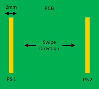
Layout guidelines for gesture detection
For detecting gestures, proximity sensor design and placement depend on the type of gesture that is to be detected. For example, to detect gestures such as horizontal swipes (along the X-axis), two parallel proximity sensors, PS1 and PS2, placed perpendicular to the horizontal hand movement, can be used as
Figure 19
shows.
The width of the sensors must not be less than 2 mm as a thumb rule; however, the length and width depend on the required sensing distance as mentioned in the Section
Size of the sensor vs. proximity sensing distance
.
Figure 19.
Layout for detecting single-axis swipe using two proximity sensors
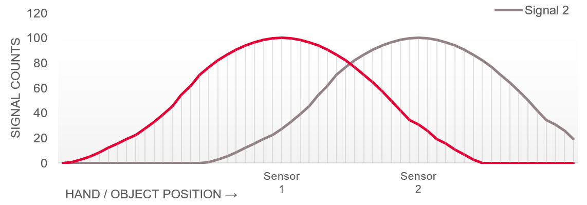
The sensor arrangement as shown in
Figure 19
results in signals as shown in
Figure 20
.
Figure 20.
Signal counts for object position over the gesture sensors
Similarly, to detect horizontal as well as vertical swipes (along both the X and Y-axis), 4 sensors can be used as shown in
Figure 21
. The two parallel proximity sensors, PS1 and PS2 are used to detect horizontal swipes (along the X-axis), and PS3 and PS4, are used to detect horizontal swipes (along the Y-axis).
Figure 21.
Proximity sensor design and placement for 2D gesture detection

Apart from being designed with multiple sensors, other aspects of the sensor design remain the same as those of a single-sensor design. All the layout guidelines are recommended to be followed for each of the sensors during the design of the gesture detection sensor.
lists the parameters and respective recommended values to be considered during the design of the gesture detection sensor layout.
Parameter | Effect on design | Recommended values |
|---|---|---|
Trace/sensor width | CP, sensitivity, and sensing distance | 2 mm |
Trace length | 5 cm | |
Distance between traces | Type of Gesture that can be detected | 5 cm for swipe-type gesture |
Layout guidelines for liquid tolerance
Making the CAPSENSE™ design liquid-tolerant requires consideration of various approaches during layout design along with the relevant firmware configuration and tuning. The two most helpful recommended layout techniques for liquid-tolerant CAPSENSE™ proximity-sensing solutions are:
Shield electrode
Guard sensor
Design of shield electrode for liquid-tolerant proximity-sensing
Adding a carefully designed shield electrode can significantly reduce the interference of liquid droplets on the sensing surface. As described in the
Shield electrode
section, design the shield electrode in and around the entire proximity sensor, preferably with the hatch pattern. Maintain a minimum distance of 2 mm between the sensor and shield electrodes.
Design of guard sensor for liquid-tolerant proximity-sensing
When a continuous liquid stream or a large amount of liquid is splashed on the sensor surface, it adds a large capacitance to the CAPSENSE™ circuitry. This capacitance might be several times larger than CF. Because of this, the effect of the shield electrode is completely masked, increasing the sensor raw count potentially higher than a target object in proximity. In such situations, the guard sensor can prevent false detections.
A guard sensor is a copper trace that surrounds all the sensors on the PCB, as
Figure 22
shows. A guard sensor is similar to a touch sensor and is used to detect the presence of a liquid stream. Multiple guard sensors can be used in combination as shown in
Figure 22
for effective sensing of the presence of a liquid.
Configure the guard sensor as a CSX sensor in combination with the proximity sensor, where the guard sensor acts as Rx and the proximity sensor acts as Tx (the proximity sensor works as the CSD sensor for target object detection and Tx for liquid detection alternatively). When a guard sensor is triggered, the firmware can disable the scanning of all other sensors in the system to prevent false detection. The firmware aspect of this technique is explained in more detail in the
Firmware guidelines for liquid tolerance
section.
Figure 22.
PCB layout with shield electrode and guard sensor
Design the guard sensor layout such that:
The guard sensor should be rectangular in shape with curved edges and surround all the sensors.
The recommended thickness for a guard sensor is 2 mm.
The recommended minimum gap between the guard sensor and the shield electrode is 2 mm.
It should be the first sensor to turn ON when there is a liquid present on the sensor surface. To accomplish this, the guard sensor surrounds all the sensors in a CAPSENSE™ system as
Figure 22
shows.
It should not be triggered when the target object is in proximity (using high threshold values). Otherwise, the proximity scanning will be disabled and the CAPSENSE™ system become non-operational until the guard sensor turns OFF.
If there is no space on the PCB for implementing a dedicated guard sensor and the design has more than one touch sensor, the guard sensor functionality can be implemented in the firmware. For example, when there is a liquid present, more than one sensor will be active at a time and the ON/OFF status of different sensors can be used to detect liquid presence.
Layout simulation
Contact
Infineon technical support
for more information on the simulation of a proposed CAPSENSE™ system layout.
1
The actual sensing distance is affected by multiple factors which are discussed in Section
Large proximity-sensing distance
earlier, the sensing distance mentioned here is based on estimation.
Firmware design guidelines
After when the proximity sensor layout is ready, the next step is to implement the firmware. This section describes the guidelines for the firmware and configuration of the CAPSENSE™ system parameters.
To learn more about using the ModusToolbox™ to create a CAPSENSE™ project, see the
PSOC™ 4: MSCLP CAPSENSE™ low-power proximity tuning
code example.
Configuring type of widgets
PSOC™ devices with fifth-generation CAPSENSE™ offer two types of widgets configurations: active and low-power widgets.
Active widgets
Active widgets are the regular widgets scanned during the active mode of the CPU and cannot be scanned during the sleep mode. All the widget types available in CAPSENSE™ configurator are by default active widget types, except the low-power widgets offered by the fifth-generation CAPSENSE™ devices.
Low-power widgets
PSOC™ devices offer multiple power modes such as Active, Sleep, Deep Sleep, etc. Devices with fifth-generation CAPSENSE™ offer the capability to keep the CAPSENSE™ peripheral active even in deep sleep mode. This capability can be implemented using a widget type called “Low-Power widget”. These widgets are scanned and processed without any CPU intervention in deep sleep mode; they can act as a wakeup source for the device.
Widgets such as buttons, ganged sensors, and proximity sensors can be configured as low-power widgets (see
Figure 23
) to enable wake-on-touch/wake-on-approach functionality.
Note:
If a widget is configured as a low-power widget for normal operation in active mode, then they need to be additionally configured as an active widget as well.
Figure 23.
Adding a low-power widget using CAPSENSE™ configurator in ModusToolbox™
Scan configuration
Scan configuration defines the distribution of the sensors among the CAPSENSE™ channels, make ganged connection, pin assignments, and scan slots assignments for each sensor channel.
Channel
A channel represents an instance of the CAPSENSE™ convertor. Infineon offers PSOC™ fifth-generation CAPSENSE™ devices with more than one channel. See the
CAPSENSE™ Controllers
page on the Infineon website to know more. Multiple channels can scan multiple sensors simultaneously, each channel scanning one sensor at a time. However, in most proximity sensing applications, the single channel should suffice.
Slot
A slot represents a time slice of complete scan cycle of (fifth-generation) CAPSENSE™. When a scan of all sensors is triggered (in fifth-generation CAPSENSE™), sensors are scanned in order of slots assigned. In multi-channel mode, a scan slot represents a group of sensors scanned together (one sensor scanned by each channel). In Single-channel mode, one sensor is scanned per scanning slot.
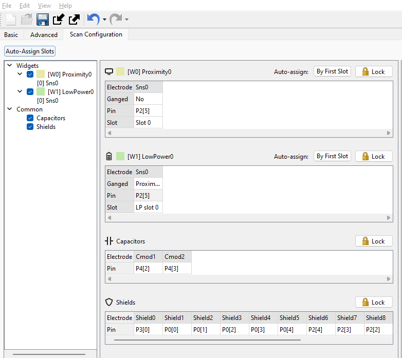
Configuring Channel and Slots
Channel and slots for the sensors can be assigned using the Scan Configuration tab in CAPSENSE™ configurator. See the
CAPSENSE™ configurator user guide
for more details.
Shield configuration
As mentioned earlier, any of the copper areas on the PCB, like hatch fill around the sensor is connected to a signal (same as that of the sensor signal) referred to as a shield electrode.
Shield electrodes can be used for the following purposes:
To implement liquid-tolerant CAPSENSE™ designs
To improve proximity sensing distance in the presence of floating or grounded conductive objects
To reduce the parasitic capacitance of the sensor
The fifth-generation CAPSENSE™ architecture supports two shield modes:
Active shield (driven shield)
Passive shield
Shield configuration can be set with CAPSENSE™ configurator in ModusToolbox™ as shown in
Figure 24
:
Figure 24.
Shield Configuration in CAPSENSE™ configurator in ModusToolbox™
Active shield
In active shielding mode, the shield circuit drives the shield electrode with a replica of the sensor signal using a buffer as shown in
Figure 25
. This nullifies the potential difference between the sensors and the shield electrode.
Figure 25.
Driven shield signal
Note:
For the shield to be effective, the clock frequency driving the shield (sense clock) must be sufficiently low so that the capacitance of the shield can charge and discharge completely.
Passive shield
In passive shielding mode, there is no buffer used instead shield is switched between VDDA and GND as shown in
Figure 26
. The switching is controlled such that the net charge between the sensor and shield is nullified every two sense clocks.
Figure 26.
Passive shield signal
Configuring shield for proximity-sensing
lists the configurable shield parameters for proximity-sensing along with their recommended values.
Parameter | Description | Recommended values |
|---|---|---|
Inactive sensor connection | Connection to the unused sensors in the system which can be set to shield or ground. | Set this parameter to value “Shield” to reduce CP and achieve liquid tolerance. |
Shield mode (5th Gen CAPSENSE™) | It defines how the shield is driven, as explained earlier – active or passive mode. | Active shield mode is recommended unless the design is required to have low power consumption in which case, Passive mode can be used. |
Total shield count | Selects the number of sensors/connections which can be connected to the shield. Inactive sensors (if set to ‘Shield’) are also counted as separate shields. | Most designs work with one dedicated shield connection but, some designs require multiple dedicated shield electrodes to ease the PCB layout routing or to reduce drive current. |
Sense clock divider | Divider to the system clock (IMO Clock Frequency); the resulting clock is used to drive the sensor and shield. | 32, if IMO clock frequency = ~46 MHz. Higher the better for the shield drive, but also increases sensor scan time |
Wake-on-approach
Wake-on-approach (WoA) refers to a scheme where the MCU device is active only when required and enters low-power modes such as sleep or deep sleep when waiting for inputs. It is a technique to reduce system power consumption significantly while keeping the system responsive to a user.
Typical applications use one of the following methods to implement WoA:
Stay in deep sleep and wake-up to a periodic interrupt source. One such source could be a watchdog timer.
Stay in deep sleep and wake-up to an external event such as a GPIO interrupt trigger.
Stay in deep sleep and wake-up to either of the above two.
PSOC™ devices with fifth-generation CAPSENSE™ offer the capability to keep CAPSENSE™ peripheral active and scan sensors in deep sleep mode, called low power always on sensing (LP-AoS). LP-AoS mode can be effectively used to implement wake-on-approach, where the approach of an object is detected by a low-power proximity sensor waking the device up and allowing for normal operation with the CPU.
In applications where touch-based sensing is the primary interface, users may not frequently operate the panel; all the touch sensors in the system can be ganged and scanned as a single proximity sensor at a very low scanning frequency. When proximity is detected, the device can stop scanning the ganged sensor and scan each sensor individually at a higher scanning frequency and detect finger touches. In such use cases, the
Sensor ganging
of the existing button sensors can be effectively used to implement the wake-on-approach technique.
Figure 27.
Example of implementation of wake-on-approach in application
A wireless computer mouse is an example where wake-on-approach using CAPSENSE™ proximity-sensing could be a perfect solution to provide always on feel while saving power. The mouse could be set to deep sleep mode when not in use and can be set to active mode as soon as the hand approaches it. As the approach of the hand itself wakes the system, the first touch will be considered for the normal operation providing always on feel.
Sensor ganging
Sensor ganging refers to simultaneously connecting multiple touch sensors to the CAPSENSE™ circuitry and scanning them as a single proximity sensor, as shown in
Figure 28
.
Figure 28.
Proximity-sensing with sensor ganging
A proximity sensor can be implemented by ganging multiple button sensors or proximity sensors. Ganging multiple sensors increases the effective sensor area and results in a large proximity-sensing distance. The CAPSENSE™ configurator in ModusToolbox™ provides an easy method to implement sensor ganging.
Consider a CAPSENSE™ system that has three button sensors. To gang these sensors, follow these steps:
Assuming the 3 button widgets are already present in the configuration as shown in
Figure 29
, add a proximity widget in the
Basic
tab in the CAPSENSE™ configurator and set the number of Sensing Element(s) to 3.
Figure 29.
Adding proximity widget in CAPSENSE™ configurator
Go to
Scan Configuration
tab and select
Ganged
option, a dropdown list will appear. Select the 3 button sensors that are already configured as shown in
Figure 30
. The dropdown list allows specifying which sensors in the system should be ganged and scanned as a single proximity sensor.
This widget now can be configured and scanned as a proximity sensor.
Figure 30.
Ganging sensors as on proximity widget in CAPSENSE™ configurator
There are advantages and disadvantages when using a dedicated proximity sensor instead of ganging the sensors together and scanning.
Parameter | Ganged proximity sensor | Dedicated proximity sensor |
|---|---|---|
Parasitic capacitance CP | High CP, requires higher resolution, higher scan time, and higher power | Lower CP |
Tuning | Difficult to tune for reliable performance because of higher CP | Easy and reliable |
Sensing range | Depends on sensors ganged together, typically much lower than the equivalent dedicated proximity sensor | 1–1.5 times the diameter/diagonal of the proximity loop |
Resources | No extra MCU pin, dedicated sensor, or dedicated space (e.g., area on PCB) required | Uses a dedicated MCU pin and dedicated space |
Apart from detecting an object in proximity, another use case of sensor ganging is to reduce the power consumption of the MCU by implementing
Wake-on-approach
.
Gesture detection firmware guidelines
Gesture detection in firmware needs to be designed at the application level. The simplest gesture detected using two sensors is a swipe, implemented similarly to the CAPSENSE™ touch slider.
The sensor arrangement as shown in
Figure 31
results in signals as shown in
Figure 32
, when a hand is swiped across them.
Figure 31.
Single-axis swipe using two proximity sensors

Figure 32.
Signal counts for object position over the gesture sensors
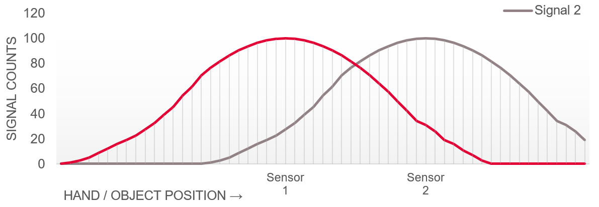
A variety of gestures can be detected using these signals. Simple horizontal X-axis swipes can be detected using an algorithm that tracks if these signals cross a threshold one after the other within the defined time limit. For example, when a left-to-right swipe is performed on the X-axis, hand position can be determined by splitting the difference counts of both the sensor into three different regions as follows:
Region A: Sensor PS1 is ON and PS2 is OFF. The hand is close to sensor PS1 and farther from sensor PS2.
Region B: Both PS1 and PS2 are ON. The hand is between PS1 and PS2
Region C: PS2 is ON and PS1 is OFF
The hand is close to PS2 and farther from PS1. When a left-to-right swipe is performed, PS1 will be triggered first, followed by PS2. This trigger pattern can be checked to interpret the gesture.
In the proximity gesture detection system, the direction of the gesture can be measured using the following attributes:
Time
Distance of the object (being detected) from all the available sensors
Number of sensors triggered
Filters
Proximity sensors are susceptible to noise because of their large sensor area and high sensitivity setting. Filters help to greatly reduce the noise in the raw count, therefore, improving the SNR and the response time. A higher SNR implies a large proximity-sensing distance and reliable sensing.
The CAPSENSE™ ecosystem features the following types of filters:
Hardware filters
Software filters
Based on what these filters are applied for, they are further classified as:
Raw count filters
Baseline filters
Because baseline is used as a reference for calculating the signal, it needs to be more stable than raw count. Therefore, a separate filter needs to be applied for the baseline than that of the raw count.
Additionally, as the CAPSENSE™ widgets can be configured as active or low power, the ecosystem offers separate filters for these types of widgets.
shows an overview of the filters offered by the CAPSENSE™ ecosystem.
Implementation | Filter application | Filter type | Active widget | Low-power widget |
|---|---|---|---|---|
Hardware | Raw count filter | CIC2 | ✓ | ✓ |
HW-IIR | ✓ | ✓ | ||
Software | Raw count filter | SW-IIR | ✓ | |
Average | ✓ | |||
Median | ✓ | |||
Baseline filter | SW-IIR | ✓ | ||
SW-IIR fast | ✓ | |||
SW-IIR slow | ✓ |
The following sections describe how to use and configure these filters effectively for proximity-sensing applications.
Hardware filters
The PSOC™ devices with fifth-generation CAPSENSE™ architecture feature two types of hardware raw count filters:
The cascaded integrator-comb 2 (CIC2) filter
First-order hardware IIR filter
This section describes these filters and their configuration in more detail.
The cascaded integrator-comb 2 (CIC2) filter
It is a second-order digital low-pass (decimation) filter for delta-sigma converters. It provides a higher resolution and thereby the SNR for a given scan period.
The CIC2 filter receives the output of the CAPSENSE™ analog front-end, which is a delta-sigma convertor. This filter as shown in
Figure 33
is a combination of a moving average low-pass filter and a down-sampler, also known as a decimator. It provides significant improvement in SNR when used along with an IIR filter.
Figure 33.
CIC2 filter block diagram
Enabling CIC2 filter
shows how the CIC2 filter can be enabled in the Advanced tab of CAPSENSE™-configurator in ModusToolbox™.
Figure 34.
Enabling CIC2 filter in Advanced tab of CAPSENSE™ configurator in ModusToolbox™
Tuning CIC2 filter
The objective of tuning the CIC2 filter is to improve conversion resolution while keeping the response time optimal. The increased resolution obtained will be in terms of increased raw count. For constant sensor capacitance (Cs), higher raw count implies higher effective resolution.
shows the maximum CIC2 output raw count that can be achieved:
Figure 35.
Maximum CIC2 output raw count equation
RawCount
max
= Decimation rate
2
A minimum of two valid samples are required for effective CIC2 filtering. Considering two valid samples, the optimum decimation rate shall be calculated using
Equation 2
as:
Figure 36.
CIC2 recommended decimation rate equation
As seen from
Equation 1
, the higher the decimation rate, the higher the maximum raw count that can be achieved and consequently, the higher the resolution (number of bits) of the signal. To achieve optimum resolution, the decimation rate must be in accordance with
Equation 2
.
Parameters to be tuned
describes the parameter that can be tuned for CIC2 filter.
Parameter | Description | Effect on raw count resolution | Dependency/trade-off |
|---|---|---|---|
Sense clock divider | Divider to the system clock (IMO); the resulting clock is used to drive the sensor signal. | Directly proportional | Sense clock divider calculations are highly dependent on sensor CP. Higher CP requires lower frequency, therefore, a higher clock divider value. Note that, lower Sense Clock will result in longer scanning time and therefore higher power consumption. |
N SUB | Number of sub conversions See the Tuning the proximity-sensing design section for more details. | Directly proportional | Increasing N SUB will increase the scan time |
See the
AN85951 - PSOC™ 4 and PSOC™ 6 MCU CAPSENSE™ design guide
for more details on the calculation of the Sense Clock Divider and NSUB.
shows CIC2 filter parameters that can be configured in the
Widget Details
tab of the CAPSENSE™ configurator in ModusToolbox™. Also, it is recommended to set the decimation rate mode parameter as ‘Auto.’
Figure 37.
Tuning CIC2 filter in Widget Details of CAPSENSE™ configurator in ModusToolbox™
First-order hardware IIR filter
This filter is used to filter raw counts of sensors (both
Active widgets
and
Low-power widgets
). Input to this filter is:
Output of CIC2 filter when CIC2 is enabled
Output of the CAPSENSE™ analog front end when CIC2 filter is disabled
represents the instantaneous output raw count of the filter:
Figure 38.
Hardware IIR filter raw count equation
where,
iirRCcoef– IIR filter raw count coefficient. The valid range is 1 to 8; a low coefficient means lower filtering, but a faster response time
Enabling hardware IIR filter
shows how the hardware IIR filter can be enabled in the
Advanced
tab of CAPSENSE™-configurator in ModusToolbox™.
Figure 39. Enabling the hardware IIR filter in the Advanced tab of CAPSENSE™-configurator in ModusToolbox™
Software filters
The CAPSENSE™ ecosystem’s middleware library offers the following types of software filters:
Raw count filters
Average
First-order IIR
Median
Baseline filters
First-order IIR for active widgets
Slow baseline IIR filter for Low power widgets
Fast baseline IIR filter for Low power widgets
For more information on the details of software filters, see the “Software filtering” section of the
Getting started with CAPSENSE™
design guide.
Software IIR filter
All the software IIR filters offered by CAPSENSE™ middleware are implemented with following equation:
Figure 40.
Software IIR filter equation
Adding software filter(s) to the project
Required software filters can be added to the ModusToolbox™ project from the Advanced tab of CAPSENSE™ configurator as shown in
Figure 41
.
Figure 41.
Adding software filter(s) to the project
Software raw count filters
Three types of raw count filters are offered by CAPSENSE™ middleware which can be configured using the CAPSENSE™ configurator tool.
Table 13
describes these filters, their applications, and respective tunable parameters.
Type | Description | Application | Tuning Parameter |
|---|---|---|---|
Average | Simple moving average filter of 4 samples length, as shown in Figure 41 . | Periodic noise from power supplies | None |
IIR | Similar to a simple RC filter, a software IIR filter with tunable IIR co-efficient, as shown in Figure 41 . | High-frequency white noise (1/f noise) | IIR co-efficient – Lower the co-efficient, higher filtering effect; The valid range: 1-128 |
Median | Similar to a moving average filter, a nonlinear filter that computes the median input value from a buffer of size 3 | Noise spikes from motors and switching power supplies | None |
Software baseline filters
Because the baseline is used as a reference for calculating the signal, it needs to be more stable than the raw count. Therefore, separate filters are offered in CAPSENSE™ middleware, which can be configured using the CAPSENSE™ configurator tool.
Type | Description | Application | Tuning Parameter |
|---|---|---|---|
First-order IIR for active widgets | A software IIR filter with tunable IIR co-efficient | High-frequency noise | IIR co-efficient – Lower the co-efficient, higher filtering effect: The valid range: 1-255 |
Slow baseline filter (5 th Gen CAPSENSE™) | IIR filter coefficient for slow changing baseline (Low power widget only) | High-frequency white noise | IIR co-efficient – Lower the co-efficient, higher filtering effect; The valid range: 1-15 |
Fast baseline filter (5 th Gen CAPSENSE™) | IIR filter coefficient for fast changing baseline (Low power widget only) | High-frequency white noise |
Firmware guidelines for liquid tolerance
This section describes guidelines for liquid tolerant firmware design.
Using self-capacitance
A simple way to make CAPSENSE™ design liquid tolerance (splash proof) is to set the detection threshold thrice that of the raw count received when a splash of liquid is present on the sensing surface. Additionally, implementation of the shield as mentioned in the Layout guidelines for liquid tolerance section is recommended to minimize the signal due to liquid presence.
See the
Tuning for liquid tolerance
section for more details on tuning the CAPSENSE™ CSD design for liquid tolerance.
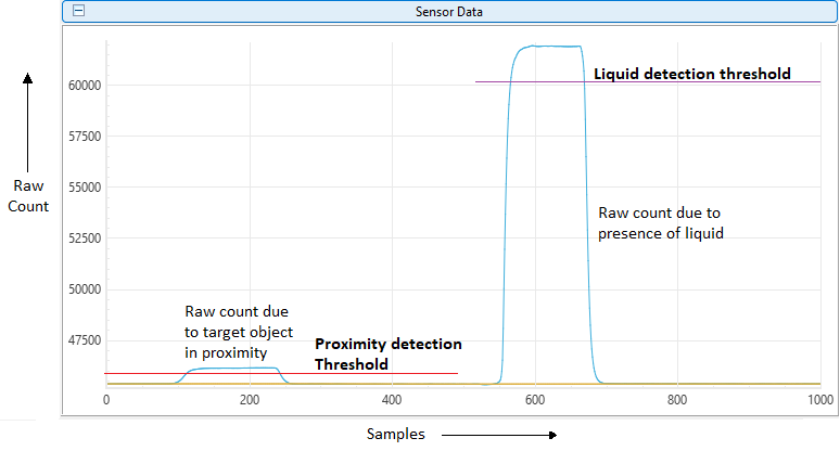
If the design comprises only of proximity sensor and does not need touch detection, a maximum limit threshold can be used for detection of a large amount of liquid as shown in
Figure 42
. Presence of a large amount of liquid (or dipping the sensor in the liquid) results in a significantly high raw count than that of the target object in proximity. The threshold to detect the presence of liquid must be higher than the maximum raw count that can be achieved when the target object being detected in proximity is closest to the sensor. Note that this technique needs to be implemented in the application.
Figure 42.
Threshold for liquid detection compared to a proximity detection signal
Using CSX guard sensors
One of the recommended techniques for liquid tolerance in CAPSENSE™-based proximity sensing is using mutual capacitive (CSX) guard sensors as mentioned in Layout guidelines for liquid tolerance.
This technique relies on the fact that the presence of liquid on the CSX-based sensor increases the mutual capacitance between Tx and Rx electrodes, as explained in the
Introduction
section. However, the presence of the human hand (or grounded object) will decrease the mutual capacitance (CM).
Figure 43.
PCB layout of guard sensor
Consider the scenario with presence of liquid on sensor setup as shown in
Figure 43
. The configuration and algorithm as shown in
Figure 44
can implemented in the application to achieve liquid tolerance.
Figure 44.
Configuration and algorithm for CSX guard sensor
Note that this technique needs to be implemented in the application with the help of middleware APIs. See the algorithm implemented in
PSOC™ 4: CAPSENSE™ MSCLP Liquid tolerant proximity sensing
code example for more information.
The methods described in this section can be used in combination to implement robust liquid tolerance.
Middleware library and APIs
Infineon provides a middleware library for CAPSENSE™ products and solutions which can be used to implement the features mentioned in this Section (
Firmware design guidelines
).
See the CAPSENSE™ middleware library help document available in the ModusToolbox™ Quick panel as shown in
Figure 45
.
Figure 45.
CAPSENSE™ middleware library help document in the ModusToolbox™
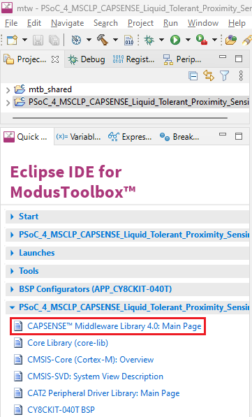
PSOC™ 4: MSCLP CAPSENSE™ low-power proximity
tuning
code example available on GitHub can serve as an excellent starting point to learn how to use Infineon’s CAPSENSE™ middleware library and respective APIs.
Tuning guidelines
After the proximity sensor layout and firmware are ready, the next step is to tune the CAPSENSE™ CSD parameters for the proximity sensor to achieve optimum performance.
The capacitance added by a target object at a distance from the proximity sensor is in tens of femtofarads, unlike touching a button sensor, where the capacitance added is in hundreds of femtofarads. To detect such a small change in capacitance, the CAPSENSE™ circuitry must be tuned for high sensitivity, and the threshold parameters should be set to the optimum values. The process of setting CAPSENSE™ CSD parameters for an optimum sensor performance is called “tuning”. This section describes how to tune the CAPSENSE™ parameters in the ModusToolbox™ for a proximity sensor to achieve optimum performance.
Signal-to-noise ratio (SNR)
Before tuning the capacitive sensor for optimal sensing, it is important to understand the concept of SNR in the context of proximity sensing and how to calculate it.
As a thumb rule, an SNR of ≥ 5:1 is required for reliable sensing. Higher the SNR, the higher the sensitivity can be achieved and consequently higher the sensing distance.
How to calculate SNR
The first step in measuring SNR is to monitor the raw count for each sensor with OFF and ON scenarios. OFF scenario is where the target object is not present in the proximity of the sensor. ON scenario is where the target object is present and is detected by the sensor. At least 3000 samples each are recommended to be logged to measure the SNR.
Another factor to consider is how the signal is produced. The worst-case ON and OFF scenarios should be used when measuring SNR. If the system is designed to sense the presence of a human hand in proximity, then measure SNR with the presence of the hand at the farthest required distance from the sensor.
Figure 46.
CAPSENSE™ signal
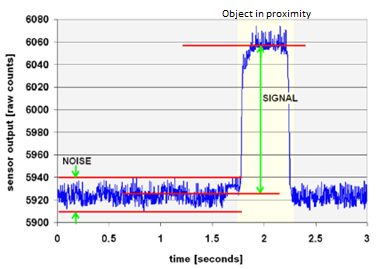
As an example of measuring SNR, consider the raw count waveform in
Figure 46
, with the calculations mentioned in
Table 15
:
Parameters | Value |
|---|---|
Minimum raw count without a hand in the proximity | 5910 counts |
Maximum raw count without a hand in the proximity | 5940 counts |
Average raw count without a hand in the proximity (baseline) | 5925 counts |
Average raw count with a hand in the proximity | 6055 counts |
Diff Count (Signal) | 6055 – 5925 = 130 counts |
Noise count | 5940 – 5910 = 30 counts |
SNR | 130:30 = 4.3 : 1 |
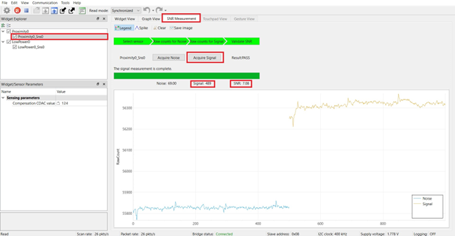
Using ModusToolbox™ to measure SNR
To make it easier, ModusToolbox™ provides a simple SNR measurement wizard for CAPSENSE™ designs as shown in
Figure 47
. However, this method supports only I2C communication with the MCU to read the sensor data and requires an application to run a specific set of APIs in the firmware. See the “Tuner GUI Interface” section in the
PSOC™ 4 CAPSENSE™ Component datasheet
.
Figure 47.
SNR measurement using CAPSENSE™ Tuner in ModusToolbox™
Note:
SNR should be measured in the noise environment where CAPSENSE™ is intended to be used. In other words, measure the system SNR under worst-case noise conditions.
Follow these steps to calculate the SNR with the help of CAPSENSE™ Tuner:
Connect the hardware to the system running ModusToolbox™
Open CAPSENSE™ Tuner and switch to the SNR Measurement tab
Select the proximity sensor in the Widget Explorer window and click Acquire Noise
After the noise is acquired, bring the target object in the proximity range of the sensor, and then click Acquire Signal. Ensure that the target object remains above the proximity loop as long as the signal acquisition is in progress.
The calculated SNR for the selected sensor will be displayed in the window.
See the
PSOC™ 4: MSCLP CAPSENSE™ low-power proximity tuning
code example for more details on measuring SNR using the CAPSENSE™ Tuner.
Table 16 describes the most relevant CAPSENSE™ parameters to maximize the SNR.
Parameter | Relation to SNR | Trade-off |
|---|---|---|
Sense clock divider | Sense clock divider is directly proportional to max raw count (when CIC2 filter is enabled) and thus the resolution of the scan, higher resolution improves SNR. | Higher sense clock divider results in a higher scan time. |
Number of sub conversions (N SUB ) | Increasing the number of sub-conversions (N SUB ) increases the signal resolution and SNR. | Higher N SUB results in Higher scan time. |
Shield mode | Shield set to active mode will be driven by the sensor signal and will help improve SNR. | Active and passive shield modes will increase power consumption. |
Raw count filter co-efficient | Higher the filter raw count co-efficient, the higher the SNR. | Higher co-efficient will lead to a slower response, higher power consumption, and longer processing times for the scan results. |
Revisiting filter configurations
The filters help to significantly improve the SNR in a CAPSENSE™ design. While trying to improve SNR, if tuning all the parameters mentioned above do not improve SNR, it is recommended to revisit filter co-efficient configurations as mentioned in the
Filters
section. Increasing the filter co-efficient will help in increasing SNR, however, will also increase the processing time and power consumption.
Tuning the proximity-sensing design
Tuning a proximity sensor shall focus on following major objectives:
Ensuring SNR ≥ 5:1
Meeting required scan and response time
Low power
Liquid tolerance (if required)
The tuning procedure for the CAPSENSE™ proximity design can be explained in following stages:
Set initial hardware parameters
Set sense clock frequency
Fine-tune for required SNR, power, and refresh rate
Tune threshold parameters
Fine tune threshold parameters for liquid tolerance if required
shows the high-level steps for tuning a proximity sensor.
Figure 48.
High-level steps for tuning a proximity sensor
Parameters to be tuned
CAPSENSE™ ecosystem provides great flexibility to support various types of CAPSENSE™ touch and proximity sensing applications.
Table 17
lists parameters along with their recommended values, available in ModusToolbox™ which are important for proximity sensing.
Parameter | Description | Recommended values |
|---|---|---|
IMO clock frequency | Frequency of clock used as source for the CAPSENSE™ peripheral | Keep it default i.e., 46 MHz (5th Gen CAPSENSE™) |
Modulator clock divider | Divider value used to divide system clock; the resulting clock then used as clock for sigma-delta modulation | 1 |
Sense clock divider | Divider to the system clock (IMO clock frequency); the resulting clock is used to drive the sensor and shields. (Value must be multiple of 4). | Set the divider such that the resulting sense clock frequency ensures proper charging and discharging of the sensor/shield electrodes. |
Clock source | Source of the clock to be used for CAPSENSE™. There are three source available:
| Keep it default i.e., Direct. |
Number of sub conversions (NSUB) | The number of sub-conversions decides the sensitivity of the sensor and sensor scan time. For a fixed modulator clock and sense clock, increasing the number of sub-conversions (NSUB) increases the signal resolution and SNR. However, increasing the number of sub-conversions also increases the scan time of the sensor according to the following equation: | Maximize this parameter till the point where SNR is >= 5:1, diff count is at least 50 and response time does not feel delayed. Minimize NSUB to reduce power consumption. |
Decimation rate (CIC2) (5th Gen CAPSENSE™) | Decimation rate or down sampling rate of CIC logic is calculated by the following equation: | Auto |
CIC2 accumulator shift (5th Gen CAPSENSE™) | Represents CIC2 hardware divider used to divide output raw count. Refer “CIC2 filter” section of AN234231 - Achieving lowest-power capacitive sensing with PSOC™ 4000T | Auto |
Proximity threshold | Raw count above which algorithm returns positive result for object detected in proximity | 80 percent of signal at maximum required distance from the sensor |
Touch threshold | Raw count above which algorithm returns positive result for touch detected on sensor | 80 percent of signal when sensor is touched |
Noise threshold | Raw count limit above which the baseline is not updated, as shown in Figure 48 . In other words, the baseline remains constant as long as the raw count is > baseline + noise threshold | 40 percent of signal. Because most of the proximity solutions, speed of human hand movement is slower to control algorithm, keep this threshold as low as possible, except when liquid tolerance is required. |
Negative noise threshold | Raw count limit below which the baseline is not updated for the number of samples specified by the low baseline reset parameter. | 40 percent of signal |
Low baseline reset | Maximum number of samples above which baseline is reset to the current raw count, if the raw count of all these samples is abnormally below the negative noise threshold. | Keep it default, i.e., 30 |
Hysteresis | Value used in addition to thresholds as mentioned below, to prevent the sensor status output from toggling due to system noise. Sensor state is reported:
| 10 percent of signal |
ON debounce | This parameter indicates the number of consecutive CAPSENSE™ scans during which a sensor must be active to generate an ON state from the system. Debounce ensures that high-frequency, high-amplitude noise does not cause false detection. | 3 |
Multi-frequency scan | Enabling multi-frequency scan, the CAPSENSE™ component performs a sensor scan with three different sense clock frequencies and obtains corresponding difference count. The median of the sensor difference-count is selected for further processing. | Use this feature for robust operation in the presence of external noise at a certain sensor scan frequency. See the code example - CE237687 - PSOC™ 4: CAPSENSE™ multi frequency scan |
CDAC auto calibration | This feature enables the firmware to automatically calibrate the CDAC (at initialization) to achieve the required calibration target of 70%. | CDAC auto-calibration is recommended to be always enabled. |
Enabling compensation CDAC | The compensation capacitor is used to compensate excess parasitic capacitance from the sensor to increase the sensitivity. Enabling this results in increased signal. | Compensation CDAC is recommended to be enabled unless the CP is too low. |
Compensation CDAC divider | Divider to ‘Sense clock divider’, which decides the number of times the compensation capacitor is switched ( K comp) in a single sense clock. Auto calibrated when ‘CDAC auto calibration’ is enabled. | Recommended to set to “Auto-calibrated”. |
Enable CDAC dither | As the input capacitance is swept, the raw count should increase linearly with capacitance. There are regions where the raw count does not change linearly with input capacitance these are called flat-spots, see section Flat-spots for more details. Dithering helps to reduce flat-spots using a dither CDAC. The dither CDAC adds white noise that moves the conversion point around the flat region | Auto |
Scan resolution (4th Gen CAPSENSE™) | Scan resolution is resolution of the sigma delta converter of CAPSENSE™. Scan resolution defines scan time and sensitivity. Increase in sensitivity increases effective proximity sensing distance. It is configurable from 6-bit to 16-bit in 4th Gen CAPSENSE™. For 5th Gen CAPSENSE™, Scan resolution is auto calculated based on multiple factors such as Modulator clock, NSUB, sense clock and use of CIC2 filter. | Maximum available (16). |
Raw count calibration level (%) | – | 85%, If the sensor raw count saturates (equals max raw count) reduce the raw count calibration level (%). This will prevent raw count saturation. |
CAPSENSE™ design tuning parameters can be tuned from CAPSENSE™ configurator in ModusToolbox™. See the
AN85951-PSOC™ 4 and PSOC™ 6 MCU CAPSENSE™ design guide
to learn more about the CAPSENSE™ parameters.
Tuning for liquid tolerance
As described in the
Firmware guidelines for liquid tolerance
section, there are two recommended techniques to implement liquid tolerance in CAPSENSE™ design. This section describes the tuning of CAPSENSE™ parameters to improve liquid tolerance.
Tuning for liquid tolerance with CSD technique
Water droplets or other liquids may create false triggers when they fall on the proximity sensor. When droplets of a liquid falls on the proximity sensor (implemented using CSD), it adds a capacitance equivalent to or more than the capacitance added when a hand is placed over the proximity sensor, which could result in false triggers. To eliminate false triggers because of liquid droplets, it is recommended to tune the CAPSENSE™ CSD parameters in such a way that when a hand is placed over the proximity sensor (at the required proximity sensing distance), the signal is at least three times greater than the signal because of liquid droplets. This ensures that the sensor will operate reliably in all conditions.
Figure 49.
Signal because of the target object in proximity vs. signal because of liquid droplets
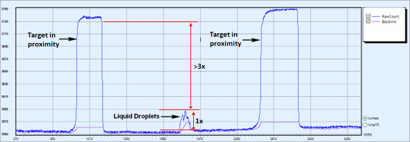
Follow these steps to tune the proximity sensing design for liquid tolerance as shown in
Figure 50
.
Figure 50.
Flow chart for tuning proximity sensor for liquid tolerance
shows the tuning parameters for the liquid tolerance technique based on CSD.
Parameters | Effect | Trade-off | Recommended value |
|---|---|---|---|
Shield mode | Active shield mode reduces the effect of sensor field line coupling to the nearby ground because of the presence of liquid, reducing the raw count measured because of the presence of liquid. | Power consumption | “Active” |
Sense clock divider | Higher value will reduce the sense clock frequency; the sense clock frequency should be low enough to allow shield capacitance to charge and discharge properly. | Scan time | Start with 28 and increase in multiple of 4 if the shield capacitance is not able to charge properly. |
Tuning for CSX guard-based liquid tolerance technique
If the CSX guard sensor technique is used for the detection of the presence of liquid, set the parameters as described in
Table 19
.
Parameters | Description and effect on CSX sensing | Recommended value |
|---|---|---|
Raw count calibration level % | Raw count calibration level indicates what the current baseline count is the percentage of maximum capacitance that can be sensed | 50% |
Number of sub conversions (NSUB) | Higher the NSUB, the higher the resolution, and therefore, the higher the sensitivity of the guard sensor | Keep it the same as the value of the proximity sensor setting |
Finger threshold | Because the presence of liquid droplets will reduce the raw count below the baseline, the positive raw count (above baseline) is not of interest, and the finger threshold can be ignored | – |
Noise threshold | Because only raw count values below baseline are used, the positive noise threshold value is to ensure the baseline is updated in accordance with noise present in the system | 40% of the signal raw count |
Negative noise threshold | Higher noise threshold will have lower sensitivity towards the small amount of liquid present. Since, baseline will be updated in case the signal due to the liquid is under the value of noise threshold. | 40% of the signal raw count is measured below the baseline when liquid is present on the surface |
Low baseline reset | Since this widget is configured as a guard, the raw count value lower than the baseline will be used to detect liquid presence. Set this value such that the baseline does not reset at all when there is a dip in the raw count because of the presence of liquid | 65535 |
Hysteresis | Hysteresis value helps avoid toggling because of variations in the raw count | Keep it the same as the value of the proximity sensor setting |
ON debounce | This parameter indicates the number of consecutive positive results required to confirm the presence of liquid; the higher the better, but will increase response time | Keep it the same as the value of the proximity sensor setting |
Liquid active threshold | This is the value against which negative difference count (= raw count – baseline) is compared to detect the presence of liquid | This value depends on the signal count measured when liquid is present on the sensor surface. This value needs to be implemented in application |
Built in self-test (BIST)
CAPSENSE™ middleware library offers BIST which allows the following features to help in designing, tuning, and debugging the CAPSENSE™ proximity sensing solutions.
Hardware tests
Sensor pins integrity check
External capacitors and sensors’ capacitance measurement
VDDA measurement
Firmware tests
Global and widget-specific configuration verification
Sensor baseline integrity check
Sensor raw count and baseline are in the specified range
See the CAPSENSE™ middleware library help as shown in
Figure 51
in the ModusToolbox™ for more details on how to implement and use the BIST.
Figure 51.
CAPSENSE™ middleware library help in ModusToolbox™
Troubleshooting tips and techniques
See the “Tuning debug FAQs” section of the AN85951 - PSOC™ 4 and PSOC™ 6 MCU CAPSENSE™ design guide for troubleshooting and debugging.
References
Revision history
Document revision | Date | Description of changes |
|---|---|---|
** | 2014-07-22 | New Application Note |
*A | 2015-09-04 |
|
*B | 2016-01-20 | Added Glossary |
*C | 2023-07-26 |
|
*D | 2023-09-12 |
|
*E | 2024-02-26 |
|
*F | 2024-03-21 | |
*G | 2025-04-02 |
Trademarks
The Bluetooth® word mark and logos are registered trademarks owned by Bluetooth SIG, Inc., and any use of such marks by Infineon is under license.
PSOC™, formerly known as PSoC™, is a trademark of Infineon Technologies. Any references to PSoC™ in this document or others shall be deemed to refer to PSOC™.
1
The actual sensing distance is affected by multiple factors which are discussed in Section
Large proximity-sensing distance
earlier, the sensing distance mentioned here is based on estimation.