Configure CM0+ project
Go to
Project > Options for Target <target_name>
, switch to the
Debug
tab, select the applicable debug probe (CMSIS-DAP or J-Link) as shown:
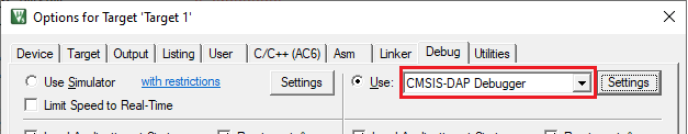
If using ULINK2, select the
CMSIS-DAP Debugger
option as the debug probe, because the ULINK2 driver does not support multi-core debugging
Click the
Settings
button to configure the target driver.
If you select the J-Link probe, a pop-up window might display reporting that the device is unknown to J-Link software.
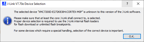
If so, click
OK
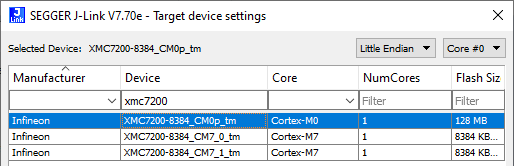
and select the device manually in the opened Target device settings dialog. For XMC7200 devices, there will be three aliases, each dedicated to a separate core.
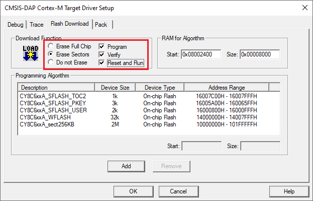
Switch to the
Flash Download
tab, select the
Erase Sectors
radio button, and select the
Program
,
Verify
, and
Reset and Run
check boxes.
Click
OK
to close the Target Driver Setup dialog.
Next, configure the project so that it also programs other image(s) from the CM4/CM7 project(s). Do this using the *.
ini
file.
Create a new empty file named load_cmx.ini and save it inside the CM0+ project directory.
Add a
LOAD
command with a path to the CM4/CM7 images. For example:
LOAD "..\proj_cm4\proj_cm4_Objects\proj_cm4.axf"
Add as many
LOAD
commands for all the CM4/CM7 projects as you have.
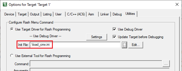
Go to
Project > Options for Target <target_name>
, select the
Utilities
tab, and specify the created
load_cmx.ini
file in the
Init File
edit field.
Switch to the
Debug
tab, and click the
Settings
button.
The configuration settings are different for CMSIS-DAP/ULINK2 and J-Link. Refer to the following sections for the applicable options:
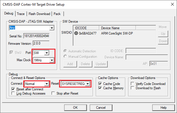
CMSIS-DAP/ULINK2 Target Driver Setup
Use the following options:
Port
: SW
Max Clock
: 1 MHz
Connect
: Normal
Reset
: SYSRESETREQ
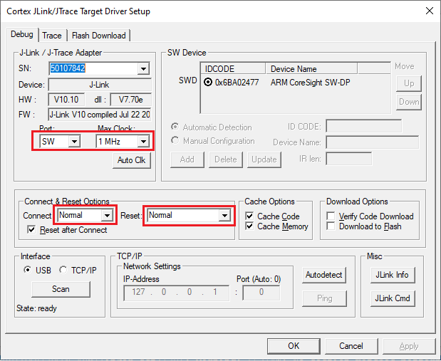
J-Link Target Driver Setup
Use the following options:
Port
: SW
Max clock
: 1 MHz
Connect
: Normal
Reset
: Normal
That completes configuring the CM0+ project. The next step is to configure CM4/CM7 project(s).