Advanced tab [all gen]
The Advanced tab provides advanced configuration parameters. In SMARTSENSE mode, most of the advanced parameters are tuned automatically. Select Manual tuning to control and configure the CAPSENSE™ middleware parameters.
The parameters in the Advanced tab are systematically arranged in the following subtabs:
-
General subtab [various gen] 1 – Contains the parameters common for all widgets irrespective of the sensing method used for the widgets.
-
CSD Settings subtab [various gen] – Contains the parameters common for widgets that use the CSD sensing method. Relevant if at least one widget uses the CSD sensing method.
-
CSX Settings subtab [various gen] – Contains the parameters common for widgets that use the CSX sensing method. Relevant if at least one widget uses the CSX sensing method.
-
ISX Settings subtab [5th gen LP] – Contains the parameters common for widgets that use the ISX sensing method. Relevant if at least one widget uses the ISX sensing method.
-
Widget Details subtab [various gen] – Contains the parameters specific to a widget and/or sensor.
Also, see the Widget Sensing Method [all gen] section.
Hover over the parameter value to display its description.
General subtab [various gen]
The General subtab contains the parameters common for all widgets irrespective of Widget Sensing Method [all gen] used for a widget.
5th generation LP CAPSENSE
5th generation CAPSENSE
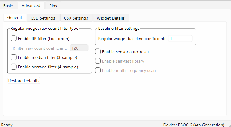
4th generation CAPSENSE
The General subtab description contains the following sections:
- Scan settings [5th gen LP], [5th gen]
- Wake-on-Touch settings [5th gen LP]
- Miscellaneous [various gen]
- Regular (non-proximity) widget – raw count filter parameters [various gen]
- Proximity widget – raw count filter parameters [various gen]
- Low Power widget – raw count filter parameters [5th gen LP]
- Baseline filter settings / Active widget baseline filter settings [various gen]
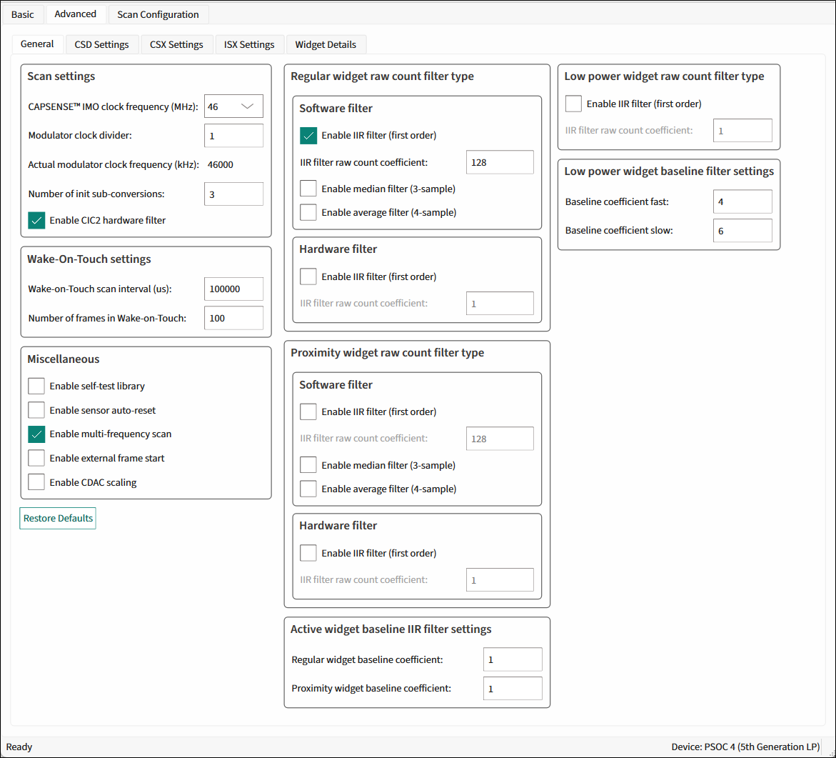
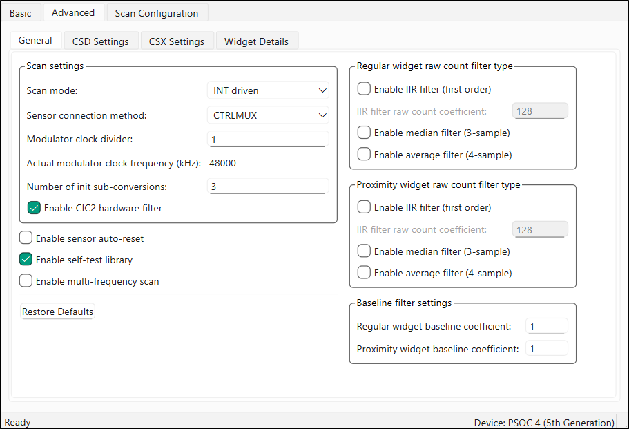
Scan settings [5th gen LP], [5th gen]
| Parameter/Group name | Description | CAPSENSE™ generation | |
|---|---|---|---|
| 5th LP | 5th | ||
| Scan mode | Selects a sensor sequencing method. INT driven (default) – In Interrupt driven mode, the CPU extracts the results and programs the MSC HW for the next scan in the scope of the End of Scan interrupt servicing routine. CS-DMA – In Chained Scan DMA mode, the DMA functionality extracts the results and programs the MSC HW for the next scan. The CPU does not need to intervene between scans | √ | |
| Sensor connection method | Selects the method how to connect a sensor to the CAPSENSE™ HW block. AMUXBUS – In this mode, the CSD sensors, shield electrodes, and Rx electrodes are connected to the MSC HW using the analog bus and can be assigned to any GPIO which supports a connection with the analog bus for the particular device. **CTRLMUX **(default)– In this mode, the CSD sensors, shield electrodes, and Rx electrodes are connected to the MSC HW using the direct connection and can be assigned to the dedicated pads only. | √ | |
| CAPSENSE™ IMO clock frequency (MHz) | The frequency of the CAPSENSE™ IMO clock. | √ | |
| Modulator clock divider | Selects the Modulator clock divider used for the CSD, CSX, and ISX sensing methods (Widget Sensing Method [all gen]). This divider defines the operating frequency of the MSC block. | √ | √ |
| Actual modulator clock frequency (kHz) | This field shows the real ModClk, which depends on the PeriClk and selected Modulator clock divider. | √ | √ |
| Number of init sub-conversions | Selects the number of initialization sub-conversions at the start of the scan. This part of scan is intended to ensure proper initialization of CAPSENSE™ hardware and does not perform the raw count measurement. | √ | √ |
| Enable CIC2 hardware filter | The cascaded integrator-comb 2 (CIC2) filter is a second-order digital low-pass (decimation) filter for delta-sigma converters. It provides a higher resolution result for the equivalent scan time. MSCLP has a built-in CIC2, which improves the effective resolution and thereby the SNR for a given scan period. | √ | √ |
Wake-on-Touch settings [5th gen LP]
| Parameter/Group name | Description |
|---|---|
| Wake-on-Touch scan interval (us) | The desired scan interval in Wake-on-Touch mode. The real interval depends on ILO frequency which have a big tolerance (above +/- 50%), see device datasheets. |
| Number of frames in Wake-on-Touch | The maximum number of frames in Wake-on-Touch mode under no touch. The valid range is [1..65535]. |
Miscellaneous [various gen]
The miscellaneous settings are applicable to the whole CAPSENSE™ middleware behavior.
| Parameter/Group name | Description | CAPSENSE™ generation | ||
|---|---|---|---|---|
| 5th LP | 5th | 4th | ||
| Enable sensor auto-reset | When enabled, the baseline is always updated and when disabled, the baseline is updated only when the difference between the baseline and raw count is less than the noise threshold. When enabled, the feature prevents the sensors from permanently turning on when the raw count accidentally rises due to a large power supply voltage fluctuation or other spurious conditions. | √ | √ | √ |
| Enable self-test library | The CAPSENSE™ middleware provides the Built-In Self-Test (BIST) library to support the design compliant with the safety-integrity level of Class B (IEC-60730) white goods and automotive, and design for manufacturing testing. The library includes a set of tests for board validation, middleware configuration, and operation. The feature includes safety functions to reduce the risk, validate boards at manufacturing, and verify the middleware operation at run-time. The BIST tests are classified into two categories: Hardware tests – To confirm the CAPSENSE™ HW block and sensor hardware (external to chip) function correctly: - Chip analog-routing verification - Pin faults checking - PCB-trace opens/shorts checking - Integration capacitors and sensors capacitance measurement - VDDA measurement FW tests – To confirm the integrity of data used for decision-making on the sensor status: - Global and widget specific configuration verification - Sensor baseline duplication - Sensor raw count and baseline are in the specified range - The application layer is responsible for running BIST tests. | √ | √ | √ |
| Enable multi-frequency scan | The MFS provides superior immunity against external noises and is suitable for applications subjected to harsh environments. MFS implementation for the 4th generation CAPSENSE™ When the MFS is enabled, each sensor is scanned three times with three different sensor frequencies. The base frequency F0 (zero channel) is the nominal sensor frequency. The second F1 and the third F2 frequencies are obtained by increasing the sense clock-divider by 1 and by 2 correspondingly. SMARTSENSE and the multi-frequency features are mutually exclusive. If SMARTSENSE is enabled, MFS cannot be enabled. Note: Enabling the MFS increases RAM usage by three times approximately. Enabling the MFS increases the sensor scan duration by three times.MFS implementation for the 5th generation and 5th generation LP CAPSENSE™ When MFS is enabled for a particular widget, the Configurator creates two supplementary widgets with the same properties but different CSD Sense clock divider or CSX Tx clock divider. The supplementary widgets have “_F1” and “_F2” suffixes in their names. Their sensors are ganged with the main widget sensors. The slot assignment should be performed manually on the Scan Configuration tab[5th gen LP], [5th gen]. The Enable multi-frequency scan check box displays as checked when the MFS is enabled for all widgets, and partially checked when the MFS is enabled only for some widgets. You can enable or disable the MFS for a particular widget on the Widget Details subtab [various gen]. SMARTSENSE * and the multi-frequency features are mutually exclusive. If the SMARTSENSE is enabled, MFS cannot be enabled for CSD widgets. Note: * 5th generation LP allows you to combine MFS with SMARTSENSE – HW parameters mode. | √ | √ | √ |
| Enable external frame start | Enables the external frame scan only under the rising edge of the signal on the dedicated pin (see Scan Configuration tab[5th gen LP], [5th gen]). The constraints for the external frame signal are as follows: - A period between the two subsequent EFS pulses is larger than the full scan duration including processing. An EFS signal that arises during the scan will be stored and the next scan will start immediately even if the processing has not completed yet. - The minimal pulse width is longer than 2 ILO cycles. - The maximal pulse width is shorter than frame duration. | √ | ||
| Enable CDAC Scaling | Applicable only for the devices having factory programmed CDAC trim code in SFLASH (Example: PSOC™ 4100-TP). | √ | ||
Regular (non-proximity) widget – raw count filter parameters [various gen]
The regular widget raw count filter applies to raw counts of sensors belonging to non-proximity widgets. These parameters can be enabled only when one or more non-proximity widgets are added to the Basic tab [all gen]. The filter algorithm is executed when any processing function is called by the application layer. When enabled, each filter consumes RAM to store a previous raw count (filter history). If multiple filters are enabled, the total filter history correspondingly increases so that the size of the total filter history is equal to a sum of all enabled filter histories.
Software filter [all gen]
| Parameter/Group name | Description |
|---|---|
| Enable IIR filter (First order) | Enables the IIR filter (See equation below) with a step response similar to an RC low-pass filter, thereby passing the low-frequency signals (finger touch responses). Output = (N) / (K) × input + ((K-N)) / (K) × previousOutput where: K is always 256. N is the IIR filter raw count coefficient selectable from 1 to 128 in the Configurator. A lower N (set in the IIR filter raw count coefficient parameter) results in lower noise, but slows down the response. This filter eliminates high-frequency noise. Consumes 2 bytes of RAM per each sensor to store a previous raw count (filter history). |
| IIR filter raw count coefficient | The coefficient (N) of IIR filter for raw counts is explained in the Enable IIR filter (First order) parameter. The range of valid values: 1-128. |
| Enable median filter (3-sample) | Enables a non-linear filter that takes three of most recent samples and computes the median value. This filter eliminates spike noise typically caused by motors and switching power supplies. Consumes 4 bytes of RAM per each sensor to store a previous raw count (filter history). |
| Enable average filter (4-sample) | The finite-impulse response filter (no feedback) with equally weighted coefficients. It takes four of most recent samples and computes their average. Eliminates periodic noise (e.g. noise from AC mains). Consumes 6 bytes of RAM per each sensor to store a previous raw count (filter history). |
| Note: If multiple filters are enabled, the execution order is as follows: 1. Median filter 2. IIR filter 3. Average filter |
Hardware filter [5th gen LP]
| Parameter/Group name | Description |
|---|---|
| Enable IIR filter (First order) | Enables the hardware IIR filter for Low Power widgets. The design of these parameters is different from the regular widget raw count filter parameters. These dedicated parameters allow for setting Low Power filter configuration and behavior differently compared to the other widgets. RawCount = (1) / (2^iirRCcoef)RawCount_New + (1-(1) / (2^iirRCcoef))RawCount_Previous where, iirRCcoef – IIR filter raw count coefficient; valid range: 1 to 8. A low coefficient means lower filtering; a higher coefficient means a higher response time. Note: There is no filtering for coefficient value “0”. |
| IIR filter raw count coefficient |
Proximity widget – raw count filter parameters [various gen]
The Proximity widget raw count filter applies to raw counts of sensors belonging to the proximity widgets. These parameters can be enabled only when one or more proximity widgets are added on the Basic tab [all gen].
Software filter [all gen]
| Parameter/Group name | Description |
|---|---|
| Enable IIR filter (First order) | The design of these parameters is the same as the Regular (non-proximity) widget – raw count filter parameters [various gen]. The Proximity sensors require high-noise reduction. These dedicated parameters allow for setting the proximity filter configuration and behavior differently compared to other widgets. |
| IIR filter raw count coefficient | |
| Enable median filter (3-sample) | |
| Enable average filter (4-sample) |
Hardware filter [5th gen LP]
| Parameter/Group name | Description |
|---|---|
| Enable IIR filter (First order) | Enables the hardware IIR filter for Proximity widgets. The equation is the same as for hardware IIR filter for regular widgets. |
| IIR filter raw count coefficient |
Low Power widget – raw count filter parameters [5th gen LP]
The Low Power widget raw count filter applies to raw counts of sensors belonging to Low Power widgets, these parameters can be enabled only when one or more Low Power widgets are added on the Basic tab [all gen].
| Parameter/Group name | Description |
|---|---|
| Enable IIR filter (First order) | Enables the hardware IIR filter for Low Power widgets. The design of these parameters is different from theRegular (non-proximity) widget – raw count filter parameters [various gen]. These dedicated parameters allow for setting Low Power filter configuration and behavior differently compared to the other widgets. RawCount = (1) / (2^iirRCcoef)RawCount_New + (1-(1) / (2^iirRCcoef))RawCount_Previous where, *iirRCcoef – *IIR filter raw count coefficient; the valid range: 1 to 8. A low coefficient means lower filtering, a higher coefficient – a higher response time. |
| IIR filter raw count coefficient | |
| Baseline coefficient (fast) | Baseline IIR filter coefficient (fast) selection for sensors in Low Power widgets only. The range of valid values: 1-15. When the raw count starts increasing, the baseline value is updated quickly to attempt to track the raw count using iirBLcoeffast. |
| Baseline coefficient (slow) | Baseline IIR filter coefficient (slow) selection for sensors in Low Power widgets only. The range of valid values: 1-15. Once the noise threshold is exceeded, the baseline is updated slowly (using iirBLcoefslow) under raw count increase due to a touch or signal event. |
Baseline filter settings / Active widget baseline filter settings [various gen]
The baseline filter settings are applied to all sensor baselines. But, filter coefficients for the Proximity, regular, and Low Power widgets can be controlled independently from each other.
The design baseline IIR filter is the same as the Enable IIR filter (First order) parameter. But, filter coefficients can be separate for both baseline and raw count filters to produce a different roll-off. The baseline filter is applied to a filtered raw count (if the widget raw count filters are enabled).
| Parameter/Group name | Description | CAPSENSE™ generation | ||
|---|---|---|---|---|
| 5th LP | 5th | 4th | ||
| Regular widget baseline coefficient | Select the Baseline IIR filter coefficient for sensors in non-proximity widgets. The range of valid values: 1-255. | √ | √ | √ |
| Proximity widget baseline coefficient | The design of these parameters is the same as the Regular widget baseline coefficient, but with a dedicated parameter allows controlling the baseline update-rate of the proximity sensors differently compared to other widgets. | √ | √ | √ |
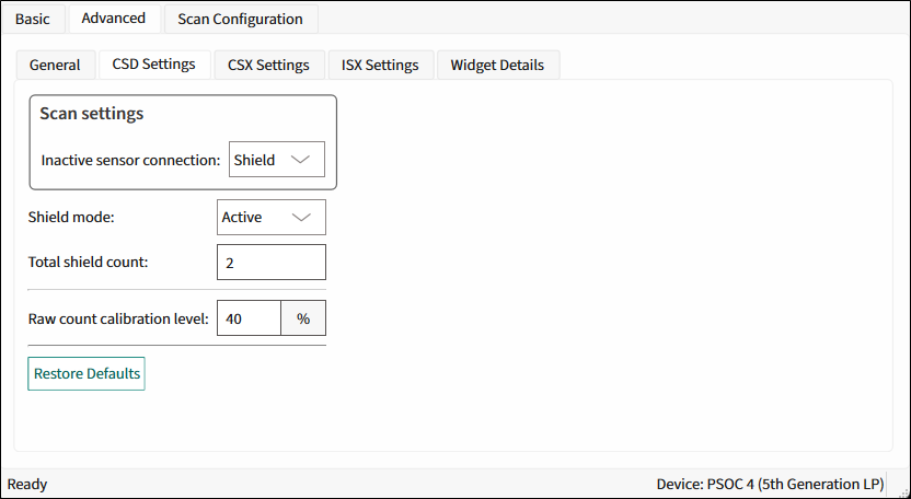
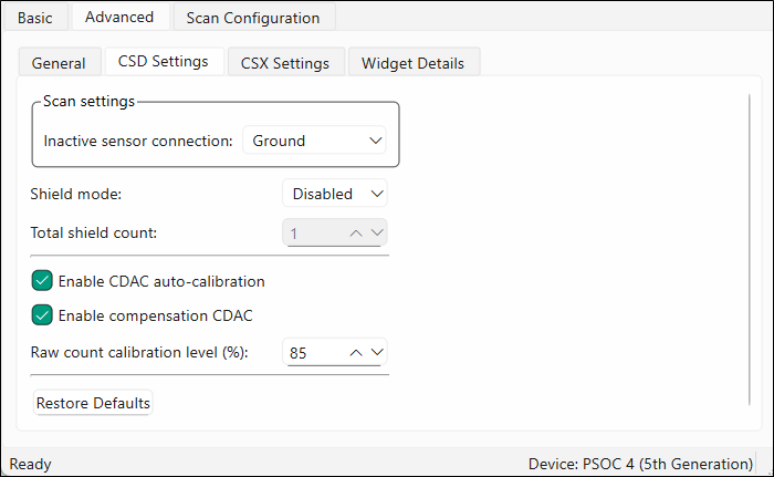
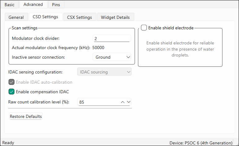
CSD Settings subtab [various gen]
Contains the parameters common for widgets that use the CSD sensing method (see Widget Sensing Method [all gen]). This subtab is relevant only if at least one widget uses the CSD sensing method.
5th generation LP CAPSENSE
5th generation CAPSENSE
4th generation CAPSENSE
CSD Settings subtab parameters [various gen]
The CSD Settings subtab contains the following parameters:
| Parameter name | Description | CAPSENSE™ generation | ||
|---|---|---|---|---|
| 5th LP | 5th | 4th | ||
| Modulator clock divider | Selects the modulator clock divider used for the CSD sensing method (see Widget Sensing Method [all gen]). Defines the operating frequency of the CSD block. | √ | ||
| Actual modulator clock frequency (kHz) | This field shows the real ModClk, which depends on the CSD peripheral clock and selected Modulator clock divider. | √ | ||
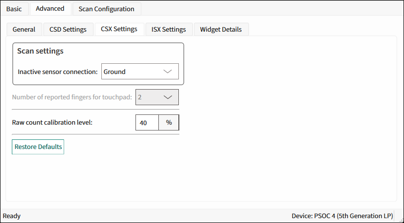
| Inactive sensor connection | Selects the state of the sensor when it is not scanned. Ground (default) – Inactive sensors are connected to the ground. High-Z – Inactive sensors are floating (not connected to GND or Shield). Shield – Inactive sensors are connected to Shield. Ground is the recommended selection for this parameter when water tolerance is not required for the design. Select Shield when the design needs water tolerance or to reduce the sensor parasitic capacitance in the design. | √ | √ | √ |
| IDAC sensing configuration | Selects the type of IDAC switching: IDAC Sourcing (default) – Sources current into the modulator capacitor (Cmod). The analog switches are configured to alternate between the Cmod and GND. IDAC Sourcing is recommended for most designs because of the better SNR. IDAC sinking – Sinks current from the modulator capacitor (Cmod). The analog switches are configured to alternate between VDD and Cmod. | √ | ||
| Enable IDAC auto-calibration | When enabled, values of the CSD widget IDACs are automatically set by the middleware. Select this parameter for robust operation and to enable SMARTSENSE. | √ | ||
| Enable compensation IDAC | Used to compensate for sensor parasitic capacitance to improve performance. Enable it unless one IDAC is required for general purpose (other than CAPSENSE™) in the application. | √ | ||
| Enable CDAC auto-calibration | When enabled, the values of the CSD widget CDACs are automatically set by the middleware. Select this parameter for robust operation. | √ | ||
| Enable compensation CDAC | Used to compensate for sensor parasitic capacitance to improve the system performance. | √ | ||
| Raw count calibration level | The raw count calibration level. | √ | √ | √ |
| Enable shield electrode | Used to reduce the sensor parasitic capacitance, enable water-tolerant CAPSENSE™ designs, and enhance the detection range for the Proximity. When the shield electrode is disabled, configurable parameters associated with the shield electrode are hidden. | √ | ||
| Enable shield tank (Csh) electrode | The shield tank capacitor is used to increase the drive capacity of the shield electrode driver. Enable it when the shield electrode capacitance is higher than 100 pF. The recommended value for a shield tank capacitor is 10nF/5V/X7R or an NP0 capacitor. The shield tank capacitor is not supported in configuration that includes both CSD and CSX sensing-based widgets. | √ | ||
| Shield SW resistance | Select the resistance of switches to drive the shield electrode. The four options: Low; Medium (default); High; Low EMI. | √ | ||
| Total shield count | Selects the number of shield electrodes required in the design. Most designs work with one dedicated shield electrode but, some designs require multiple dedicated shield electrodes to ease the PCB layout routing or to minimize the PCB area used for the shield layer.The minimum value is 0 (for example, shield signal could be routed to sensors using the Inactive sensor connection parameter) and the maximum value is equal to the total number of CAPSENSE™-enabled port pins available for the selected device. | √ | √ | ��√ |
| Shield mode | Selects the shield drive. The options: **Disabled **(default) – No shield. In this mode the configurable parameters associated with it are not applicable. Active – A shield circuit drives the shield electrode with a replica of the sensor signal. The internal buffer operational amplifier (opamp) is used to drive the VDDA/2 voltage onto the shield pin during the corresponding phases. The Active shielding provides better capabilities in comparison to the Passive shielding. For high-performance applications, recommended the shield electrode capacitance less than 1.2nF. 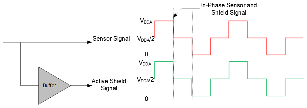 Passive – In this mode the buffer is not used, instead the shield is switched between VDDA and GND. The Passive shielding provides worse shielding capabilities in comparison to the Active shielding since it does not replicate the sensor signal. The Passive shielding is preferred for low power applications if high shielding performance is not critical. 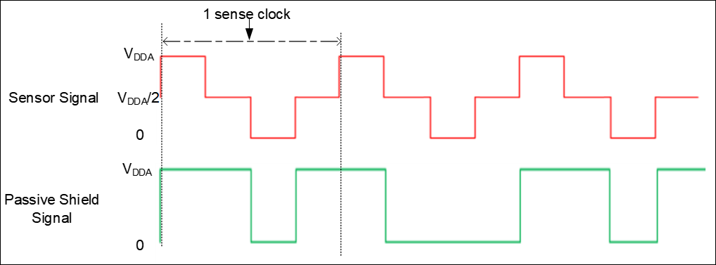 | √ | √ | |
Commands:
- Restore Defaults - Restores parameters values on the current tab to their default values.
CSX Settings subtab [various gen]
Contains the parameters common for widgets that use the CSX sensing method (see Widget Sensing Method [all gen]). This subtab is relevant only if at least one widget uses the CSX sensing method.
5th generation LP CAPSENSE
5th generation CAPSENSE
4th generation CAPSENSE
CSX Settings subtab parameters [various gen]
The CSX Settings subtab contains the following parameters:
| Parameter name | Description | CAPSENSE™ generation | ||
|---|---|---|---|---|
| 5th LP | 5th | 4th | ||
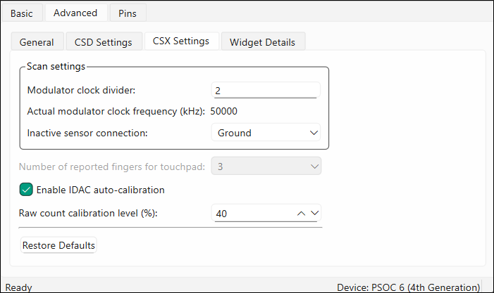
| Modulator clock divider | Selects the modulator clock divider used for the CSX sensing method (see Widget Sensing Method [all gen]). Defines the operating frequency of the CSX block. A higher modulator clock frequency reduces the sensor scan time, results in lower power, and reduces the noise in raw counts, so use the highest possible frequency. | √ | ||
| Actual modulator clock frequency (kHz) | This field shows the real ModClk, which depends on the CSX peripheral clock and selected Modulator clock divider. | √ | ||
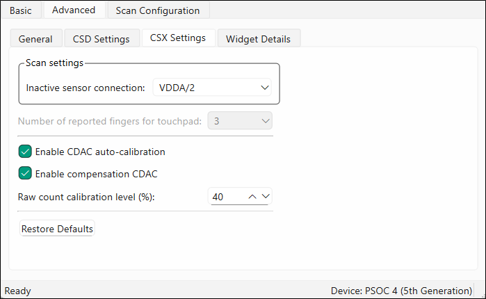
| Inactive sensor connection | Selects the state of the sensor when it is not scanned. Ground (default) – Inactive sensors are connected to the ground. High-Z – Inactive sensors are floating (not connected to GND or Shield). VDDA/2 – Inactive sensors are connected to the VDDA/2 voltage level source. | √ | √ | √ |
| √ | √ | |||
| Number of reported fingers for Touchpad | Sets the number of reported fingers for CSX Touchpad widgets only. The available options are from 1 to 3. | √ | √ | √ |
| Enable IDAC auto-calibration | When enabled, IDAC values are automatically set by the middleware. Recommended to select the Enable IDAC auto-calibration for robust operation. | √ | ||
| Enable CDAC auto-calibration | When enabled, the values of the CSX widget CDACs are automatically set by the middleware. Select this parameter for robust operation. | √ | ||
| Enable compensation CDAC | Used to compensate for sensor parasitic capacitance to improve the system performance. | √ | ||
| Raw count calibration level | The raw count calibration level in percentage for CSX widgets. | √ | √ | √ |
Commands:
- Restore Defaults - Restores parameters values on the current tab to their default values.
ISX Settings subtab [5th gen LP]
Contains the parameters common for widgets that use the ISX sensing method (see Widget Sensing Method [all gen]). This subtab is relevant only if at least one widget uses the ISX sensing method.
ISX Settings subtab parameters [5th gen LP]
The ISX Settings subtab contains the following parameters:
| Parameter | Description | |
|---|---|---|
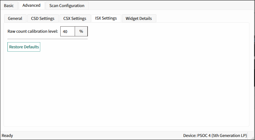
| Raw count calibration level (%) | The raw count calibration level in percent. | |
Commands:
- Restore Defaults - Restores parameters values on the current tab to their default values.
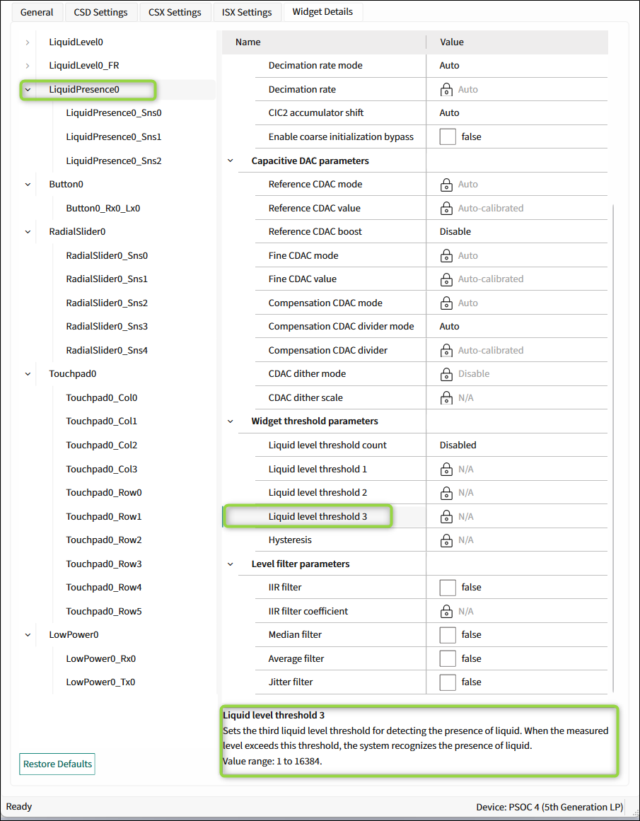
Widget Details subtab [various gen]
Contains parameters unique for each widget type and sensor. When you select a parameter, its description displays on the panel below the parameters list. Refer to the Widget Types section for the description of the available widgets.
These parameters are set automatically when SMARTSENSE is enabled, manually when disabled.
Commands:
- Restore Defaults - Restores parameters values on the current tab to their default values.
The Widget Details subtab contains the parameters described in the below sections:
- Widget general parameters [various gen]
- Widget hardware parameters [various gen]
- Capacitive DAC parameters [5th gen LP]
- Widget threshold parameters [all gen]
- ALP filter parameters [5th gen LP]
- Raw count filter parameters [all gen]
- Position / Level filter parameters
- Adaptive IIR filter parameters [all gen]
- Centroid parameters [all gen]
- Ballistic multiplier parameters [all gen]
- Gesture parameters
- Sensor parameters [various gen]
Widget general parameters [various gen]
Description
| Parameter name | Description | |||
|---|---|---|---|---|
| Diplexing | Enabling Diplexing allows doubling the Linear Slider physical touch sensing area by using the specific diplexing sensor pattern and without using additional port pins and sensors. | |||
| Maximum position | Represents the maximum centroid position for the Linear Slider/Radial Slider. A touch on a slider produces a position value from 0 to the maximum position-value set. No Touch produces 0x0000. | |||
| Maximum X-axis position | Represents the maximum column (X-axis) centroid position and row (Y-axis) centroid positions for a Touchpad. A touch on a Touchpad widget produces a position value from 0 to the maximum position set. No Touch produces 0x0000. | |||
| Enable multi-frequency scan | Enables the multi-frequency scan for the current widget. Refer to Enable multi-frequency scan for details. | |||
| Enable foam rejection | Set this parameter to true to create the Liquid Level Foam Rejection (FR) sub-widget, which calculates a liquid level excluding foam. Liquid Level FR sensors are ganged with the Liquid Level widget’s sensors. Assign slots manually on the tab. Scan Configuration tab[5th gen LP], [5th gen] | |||
| Enable tank removal detection | Enables the tank absence or removal detection. | |||
| Foam correction coefficient | Set this parameter to true to create the Liquid Level Foam Rejection (FR) sub-widget, which calculates a liquid level excluding foam. Liquid Level FR sensors are ganged with the Liquid Level widget’s sensors. Assign slots manually on the Scan Configuration tab[5th gen LP], [5th gen] tab. Sets the foam correction (rejection) coefficient. Displays when the Liquid Level foam rejection widget is enabled. The foam rejection coefficient: 256 × (Level_FoamRejection − Level_known) / (Level_LiquidLevel − Level_FoamRejection) where: Level_FoamRejection is the level reported by the Liquid Level foam rejection widget – to obtain the correct result, set the foam rejection coefficient to "0". Level_LiquidLevel is the level reported by the Liquid Level widget. Level_known is the real liquid level in the tank without foam. Note: To obtain better results, fill the tank with some liquid and create maximum foam.The value range is 0-4095. | |||
| Maximum level | Represents the maximum measurable capacity of the sensor. The sensor produces the measured liquid level starting from value 0 to the maximum level set. The value range is 1-16384. | |||
Applicability
| Parameter name | CAPSENSE™ generation | Sensing method/Widget | ||||
|---|---|---|---|---|---|---|
| 5th LP | 5th | 4th | CSD | CSX | ISX | |
| Diplexing | √ | √ | √ | Linear Slider | ||
| Maximum position | √ | √ | √ | Linear Slider Radial Slider | Linear Slider | |
| Maximum X-axis position | √ | √ | √ | Touchpad | ||
| Maximum -X-axis position | √ | √ | √ | Touchpad | N/A | |
| Maximum Y-axis position | √ | √ | √ | |||
| Enable multi-frequency scan | √ | √ | Button Linear Radial Slider Matrix Buttons Touchpad Proximity Low Power | Button Linear Slider Matrix Buttons Touchpad Low Power | Button Linear Slider Proximity Low Power | |
| Enable foam rejection | √ | Liquid Level Liquid Level Presence | N/A | N/A | ||
| Foam correction coefficient | √ | |||||
| Enable tank removal detection | √ | |||||
| Maximum level | √ | |||||
Widget hardware parameters [various gen]
Description
| Parameter/Group name | Description | |||
|---|---|---|---|---|
| Touch sensitivity (pF/µH) | See Touch Sensitivity [all gen] for the description. | |||
| Sense clock divider | Sets the CSD Sense clock divider. For the 5th generation CAPSENSE™, the value will be a multiple of 4. When SMARTSENSE is selected in Basic tab [all gen], the Sense clock divider is automatically set by the middleware to an optimal value by following the 25RC rule for the 4th generation CAPSENSE™ and 45*RC for the 5 generation CAPSENSE™ (refer to CAPSENSE™ design guide for more information on this rule) and this control is not editable. | |||
| Column sense clock divider | Sets the CSD Sense clock divider for row and column sensors of the Matrix Buttons and Touchpad. For the 5th generation CAPSENSE™, the value will be a multiple of 4. | |||
| Row sense clock divider | ||||
| Tx clock divider | Sets the Tx clock divider for the CSX widgets. For the 5th generation CAPSENSE™, the value will be a multiple of 2. | |||
| Tx clock source | The Tx clock frequency derives from the modulator clock frequency using a clock-divider and is used to sample the sensor. Both the clock source and clock divider are configurable. The Spread Spectrum Clock (SSC) provides a dithering clock source with a center frequency equal to the Tx clock frequency and the Direct source disables the SSC source and uses a fixed frequency clock. The SSC reduces the radiated noise by spreading the clock and improves the immunity against external noise. Using a higher number of bits of SSC lowers the radiation and increases the immunity against external noise. The following clock sources are available: - Direct – SSC is disabled and a fixed clock is used. - SSC6, SSC7, SSC9 and SSC10 – The clock spreads using from 6 to 10 bits of the sense-clock divider respectively. - Auto – The middleware automatically selects optimal SSC or Direct sources individually for each widget. Auto is the recommended sense clock source selection. The rules and recommendations for the SSC selection: - The ratio between the modulator clock frequency and Tx clock frequency must be greater than or equal to 20. - 20% of the Tx clock divider should be greater or equal to the SSC frequency range = 32. It allows varying the ratio between the modulator and Tx clock frequencies to 32 different clocks evenly spaced over +/- 10% from the center frequency. TxClkDiv ≥ 160 where TxClkDiv is Tx clock divider. Recommended that at least one full-spread spectrum polynomial complete during the scan time. N_Sub ≥ 2^∧SSCN − 1 where N_Sub is the number of sub-conversions, SSCN is the number of bits used for SSC (6, 7, 9 and 10). Recommended that the number of sub-conversions for the widget be an integer multiple of the SSC polynomial selected. For example, if SSC6 is selected, the number of sub-conversions should be multiple of (2SSC6-1) = 63. | |||
| Sense clock source | The Sense clock frequency is derived from the modulator clock frequency using a clock-divider and is used to sample the sensor. Both the clock source and clock divider are configurable. The Spread Spectrum Clock (SSC) provides a dithering clock source with a center frequency equal to the sense clock frequency. The Pseudo-Random Sequencer (PRS) clock source spreads the clock using the pseudo-random sequence and the Direct source disables both SSC and PRS sources and uses a fixed-frequency clock. Both PRS and SSC reduce the radiated noise by spreading the clock and improve the immunity against external noise. Using a higher number of bits of SSC and PRS lowers the radiation and increases the immunity against external noise. The following sources are available: - Direct – PRS and SSC are disabled and a fixed clock is used. - PRS8 – The clock spreads using PRS to modulator clock / 256. - PRS12 – The clock spreads using PRS to modulator clock / 4096. - SSC6, SSC7, SSC9 and SSC10 – The clock spreads using from 6 to 10 bits of the sense-clock divider respectively. - Auto – The middleware automatically selects optimal SSC, PRS or Direct sources individually for each widget. The Auto is the recommended sense clock source selection. The rules and recommendations for the SSC selection: - The ratio between the modulator clock frequency and sense clock frequency must be greater than or equal to 20. - 20% of the ratio between the modulator clock frequency and sense clock frequency will be greater or equal to the SSC frequency range = 32, which allows varying the ratio between the modulator and sense clock frequencies to 32 different clocks evenly spaced over +/- 10% from the center frequency: 160 ≤ SnsClkDiv where SnsClkDiv is sense clock divider. Recommended that at least one full-spread spectrum polynomial complete during the scan time: (2^∧N − 1)/SnsClkDiv ≥ 2^∧SSCN − 1 where N is the Scan resolution, SSCN is the number of bits used for SSC (6, 7, 9 and 10), and SnsClkDiv is sense clock divider. Recommended that the number of sub-conversions for the widget be an integer multiple of the SSC polynomial selected. For example, if SSC6 is selected, the number of the sub-conversion should be multiple of (2^SSC6-1) = 63. The recommendation for the PRS selection: At least one full PRS polynomial completes during the scan time: (2^∧N − 1)/SnsClkDiv ≥ 2^∧PRCN − 1 where N is the Scan resolution, PRSN is the number of bits used for PRS (8 and 12), ModClk is the Modulator clock frequency and SnsClk is the average sense clock frequency. | |||
| Clock source | The clock frequency is used to sample the sensor. It is derived from the modulator clock frequency using a clock divider. Both the clock source and clock divider are configurable. The Spread Spectrum Clock (SSC) provides a dithering clock source with a center frequency equal to the sense clock frequency. The PRS clock source spreads the clock using the pseudo-random sequencer and the Direct source disables both SSC and PRS sources and uses a fixed-frequency clock. Both PRS and SSC reduce the radiated noise by spreading the clock and improve the immunity against external noise. Using a higher number of bits of SSC and PRS lowers the radiation and increases the immunity against external noise. The sources: - Direct – Disable PRS and SSC, and use a fixed clock. - SSC – The clock spreads by variation of the sense-clock divider in the [-16,15] range. - PRS – The clock spreads using PRS to the sensor clock. - SSC Auto – The middleware automatically selects the optimal SSC or Direct sources individually for each widget. - PRS Auto – The middleware automatically selects the optimal PRS or Direct sources individually for each widget. | Sensing method | LFSR range | Sense clock divider Min | Sense clock divider Max | | --- | --- | --- | --- | | CSD | [-2; 1] | 10 | 4095 | | CSD | [-4; 3] | 12 | 4094 | | CSD | [-8; 7] | 16 | 4089 | | CSD | [-16; 15] | 24 | 4081 | | CSD | Auto | 10 | 4095 | | CSX | [-2; 1] | 6 | 4094 | | CSX | [-4; 3] | 8 | 4092 | | CSX | [-8; 7] | 12 | 4088 | | CSX | [-16; 15] | 20 | 4080 | | CSX | Auto | 6 | 4094 | The rules and recommendations for the SSC selection: | |||
| LFSR range | The linear-feedback shift register (LFSR). For CSD widgets, sets the sense clock divider deviation range. For CSX widgets, sets the Tx clock divider deviation range. For example, if the clock divider is set to 16 and LFSR range to [-2; 1], the MSC HW block will vary the clock divider in the range from 14(16 – 2) to 17 (16 + 1) during a scan. This parameter is editable when the clock source is SSC or SSC Auto. | |||
| Decimation rate mode | Decimation rate mode is set automatically by the middleware or manually depending on the mode. | |||
| Decimation rate | Sets the configurable decimation rate when Enable CIC2 hardware filter is enabled. The minimum recommended value considering two valid CIC2 samples (valid samples = Total CIC2 samples - 1): Decimationrate(N) ≤ (Sns_Clk_Div × Nsub) / (3) | |||
| CIC2 accumulator shift | The CIC2 and Row CIC2 accumulator shifts set the right shift value applied to the CIC2 accumulator to form raw counts when the Enable CIC2 hardware filter is enabled. Both parameters are configurable. | |||
| Row CIC2 accumulator shift | ||||
| Scan resolution | Selects the scan resolution of the CSD widgets (the resolution of the capacitance-to-digital conversion). Acceptable values are from 6 to 16 bits. | |||
| Reference CDAC value | Sets the reference CDAC value for the Button, Slider or Proximity. This parameter's value is set automatically when Reference CDAC mode is set to the AUTO value or Enable CDAC auto-calibration is selected in the CSD Settings subtab [various gen]) is selected. | |||
| Row reference CDAC value | These parameters set separate CDAC values for the row and column sensors of the Matrix Buttonsand Touchpad. These parameters' values are set automatically when Reference CDAC mode is set to the AUTO value or Enable CDAC auto-calibration is selected in the CSD Settings subtab [various gen]) is selected. | |||
| Column reference CDAC value | ||||
| CDAC dither mode | Select CDAC dither mode used to reduce Flat-spots (or dead zones). | |||
| CDAC dither scale | CDAC dither value in bits. The parameter's value is set automatically when the parameter is set to the AUTO value. | |||
| Compensation CDAC divider | The ratio between the modulator clock frequency and compensation CDAC switching frequency. The ratio between the Sense clock divider and Compensation CDAC divider shows the number of times the compensation CDAC switches in the sense clock period. The value range is [3 .. 4095]. | |||
| Number of sub-conversions | Selects the number of sub-conversions. For the CSD block, applicable to the CSX and ISX sensing methods (). | |||
| Modulator IDAC | Sets the modulator IDAC value for the Button (CSD), Slider, or Proximity. The value of this parameter is automatically set when Enable IDAC auto-calibration is selected in the (CSD Settings subtab [various gen]). | |||
| Row modulator IDAC | Sets a separate modulator IDAC value for the row and column sensors of the Matrix Buttons (CSD) and Touchpad. These parameters values are automatically set when Enable IDAC auto-calibration is selected in the (CSD Settings subtab [various gen]). | |||
| Column modulator IDAC | ||||
| IDAC gain index | Sets the IDAC gain index. Options include: - Index 0 – 37.5 nA - Index 1 – 75 nA - Index 2 – 300 nA (default for CSX widgets) - Index 3 – 600 nA - Index 4 – 2400 nA (default for CSD widgets) - Index 5 – 4800 nA - Index 6 – 1200 nA The value of this parameter is automatically set when Enable IDAC auto-calibration is selected. | |||
| Enable coarse initialization bypass | Enables skipping the coarse initialization and thus, the scan refresh rate increases. | |||
| Multi-phase Tx order | The Multi-phase Tx technic is used for mutual capacitance sensing. The Tx driver is modulated with different patterns by the firmware and the result is de-convoluted. The advantage is a higher SNR because MPTX performs spatial filtering of the result with sqrt(N) improvement in noise, where N is the number of driven lines and the scan is performed by N times longer than a single sensor scan. The parameter becomes visible if the Tx electrodes number is greater than 3. | |||
Applicability
| Parameter name | CAPSENSE™ generation | Sensing method/Widget | ||||
|---|---|---|---|---|---|---|
| 5th LP | 5th | 4th | CSD | CSX | ISX | |
| Touch sensitivity (pF/µH) | √ | √ | √ | Button Linear Radial Slider Matrix Buttons Touchpad Proximity | N/A | Button Linear Slider Proximity |
| Sense clock divider | √ | √ | √ | All widgets | N/A | N/A |
| Column sense clock divider | √ | √ | √ | Matrix Buttons Touchpad | N/A | |
| Row sense clock divider | √ | √ | √ | |||
| Sense clock source | √ | Button Linear Slider Radial Slider Matrix Buttons Touchpad Proximity | N/A | |||
| Tx clock divider | √ | √ | √ | N/A | Button Linear Slider Matrix Buttons Touchpad Low Power | N/A |
| Tx clock source | √ | N/A | Button Linear Slider Matrix Buttons Touchpad | Button Linear Slider Proximity | ||
| Lx clock divider | √ | N/A | Button Linear Slider Proximity Low Power | |||
| Clock source | √ | √ | All widgets | Button Linear Slider Matrix Buttons Touchpad Low Power | Button Linear Slider Proximity Low Power | |
| LFSR range | √ | √ | ||||
| Decimation rate mode | √ | √ | ||||
| Decimation rate | √ | √ | ||||
| CIC2 accumulator shift | √ | |||||
| Row CIC2 accumulator shift | √ | Matrix Buttons Touchpad | N/A | |||
| Scan resolution | √ | Button Linear Slider Radial Slider Matrix Buttons Touchpad Proximity | N/A | |||
| Reference CDAC mode | √ | All widgets | Button Linear Slider Radial Slider Matrix Buttons Touchpad Proximity | Button Linear Slider Matrix Buttons Touchpad | ||
| Reference CDAC value | √ | Button Linear Slider Radial Slider Proximity | Button Linear Slider Matrix Buttons Touchpad | N/A | ||
| Column reference CDAC value | √ | Matrix Buttons Touchpad | N/A | |||
| Row reference CDAC value | √ | |||||
| CDAC dither mode | √ | Button Linear Slider Radial Slider Matrix Buttons Touchpad Proximity | Button Linear Slider Matrix Buttons Touchpad | N/A | ||
| CDAC dither scale | √ | |||||
| Compensation CDAC divider | √ | |||||
| Number of sub-conversions | √ | √ | √ | All widgets | Button Linear Slider Matrix Buttons Touchpad Low Power | Button Linear Slider Proximity Low Power |
| Modulator IDAC | √ | Button Linear Slider Radial Slider Proximity | N/A | |||
| Column modulator IDAC | √ | Matrix Buttons Touchpad | N/A | |||
| Row modulator IDAC | √ | |||||
| IDAC gain index | √ | Button Linear Slider Radial Slider Matrix Buttons Touchpad Proximity | N/A | |||
| Enable coarse initialization bypass | √ | All widgets | Button Linear Slider Matrix Buttons Touchpad Low Power | Button Linear Slider Proximity Low Power | ||
| Multi-phase Tx order | √ | √ | N/A | Touchpad | N/A | |
Capacitive DAC parameters [5th gen LP]
Description
| Parameter name | Description |
|---|---|
| Reference CDAC mode | Selects the Reference CDAC mode. |
| Reference CDAC value | Sets the reference CDAC value for the Button, Linear Slider/Radial Slideror Proximity widget. These parameter's value is set automatically when Reference CDAC mode is set to the AUTO value or Enable CDAC auto-calibration (CSD Settings subtab [various gen]) is selected. |
| Row reference CDAC value | These parameters set separate CDAC values for the row and column sensors of the Matrix Buttons and Touchpad. These parameter's value is set automatically when Reference CDAC mode is set to the AUTO value or Enable CDAC auto-calibration (CSD Settings subtab [various gen]) is selected. |
| Column reference CDAC value | |
| Reference CDAC boost | Increases the sensitivity by 2x, 3x, and 4x. Achieved by dividing the actual Reference CDAC values by the factors of 2,3, and 4 for auto-calibration. |
| Fine CDAC mode | Selects Fine CDAC mode. The Fine CDAC is a programmable CDAC used to achieve finer resolution for the Reference CDAC. |
| Fine CDAC value | These parameters are available when Fine CDAC mode is set to the MANUAL value. Sets Fine CDAC values separately for the row and column sensors of the Matrix Buttonsand Touchpad. These parameters values are set automatically when Fine CDAC mode is set to the AUTO value. |
| Row fine CDAC value | |
| Column fine CDAC value | |
| Compensation CDAC mode | Selects Compensation CDAC mode used to compensate for sensor mutual capacitance in order to improve the system performance. |
| Compensation CDAC divider mode | Select Compensation CDAC divider mode. This parameter depends on Compensation CDAC mode. |
| Compensation CDAC divider | The ratio between the Modulator clock frequency and Compensation CDAC switching frequency. The ratio between the Sense clock divider and Compensation CDAC divider shows the number of times the Compensation CDAC switches in the sense clock period. The value range is [3..4095]. |
| CDAC dither mode | Selects CDAC dither mode used to reduce Flat-spots (or dead zones). |
| CDAC dither scale | CDAC dither value in bits. The parameter's value is set automatically when CDAC dither mode is set to the AUTO value. |
Applicability
| Parameter name | Sensing method/Widget | ||
|---|---|---|---|
| CSD | CSX | ISX | |
| Reference CDAC mode | All widgets | Button Linear Slider Matrix Buttons Touchpad Low Power | Button Linear Slider Proximity Low Power |
| Reference CDAC value | Button Linear Slider Radial Slider Proximity Low Power Liquid Level Liquid Presence | Button Linear Slider Matrix Buttons Touchpad Low Power | Button Linear Slider Proximity Low Power |
| Column reference CDAC value | Matrix Buttons Touchpad | N/A | |
| Row reference CDAC value | |||
| Reference CDAC boost | All widgets | Button Linear Slider Matrix Buttons Touchpad Low Power | Button Linear Slider Proximity Low Power |
| Fine CDAC mode | |||
| Fine CDAC value | All widgets | Button Linear Slider Matrix Buttons Touchpad Low Power | Button Linear Slider Proximity Low Power |
| Column fine CDAC value | Matrix Buttons Touchpad | N/A | |
| Row fine CDAC value | |||
| Compensation CDAC mode | All widgets | Button Linear Slider Matrix Buttons Touchpad Low Power | Button Linear Slider Proximity Low Power |
| Compensation CDAC divider mode | |||
| Compensation CDAC divider | |||
| CDAC dither mode | |||
| CDAC dither scale | |||
Widget threshold parameters [all gen]
All threshold parameters for the CSD widgets belong to all CAPSENSE™ generations , except for Liquid Presence, which is possible only for the 5th LP generation.
Description
| Parameter name | Description |
|---|---|
| Proximity threshold | The design of the Proximity touch threshold and Proximity threshold parameters is the same as for the Finger threshold parameter. The proximity sensor requires a higher noise reduction, and supports two levels of detection: The proximity level to detect an approaching hand or finger. The touch level to detect a finger touch on the sensor similarly to other Widget Types [all gen] sensors. Note that for valid operation, the Proximity touch threshold must be higher than the Finger threshold. The threshold parameters such as Hysteresis and ON debounce are applicable to both detection levels. |
| Proximity touch threshold | |
| Finger threshold | The finger threshold parameter is used along with the hysteresis parameter to determine the sensor state as follows: - ON – Response signal > (Finger Threshold + Hysteresis) - OFF – Response signal ≤ (Finger Threshold – Hysteresis) Note that "Signal" in the above equations refers to: Signal = Raw Count – Baseline. Recommended to set the Finger threshold parameter value equal to the 80% of the touch signal. The Finger Threshold parameter is not available for the Proximity widget. Instead, the Proximity widget has two thresholds: - Proximity threshold - Proximity touch threshold |
| Noise threshold | Sets a signal limit, below which a signal is considered as noise. When a signal is above the Noise Threshold, a difference count is produced and the baseline is updated only if Enable sensor auto-reset is selected. If it is not selected, the baseline remains constant as long as the raw count is above the baseline + noise threshold. This prevents the baseline from following the raw counts during a finger touch detection event. Recommended to set the noise threshold parameter value equal to 2x noise in the raw count or the 40% of the signal. |
| Negative noise threshold | Sets an absolute signal value limit below which the baseline is not updated for the number of samples specified by the Low baseline reset parameter. The negative noise threshold ensures that the baseline does not fall low because of any high-amplitude repeated negative-noise spikes on a raw count caused by different noise sources such as ESD events. Recommended to set the negative noise threshold parameter value equal to the Noise threshold parameter value. |
| Low baseline reset | This parameter is used along with the Negative noise threshold parameter. It counts the number of abnormally low raw counts required to reset the baseline. If a finger is placed on the sensor during a device startup, the baseline gets initialized to a high raw count value at startup. When the finger is removed, the raw count falls to a lower value. In this case, the baseline should track low raw counts. The Low baseline reset parameter helps handle this event. It resets the baseline to a low raw count value when the number of low samples reaches the low-baseline reset number. Note: After a finger is removed from the sensor, the sensor will not respond to finger touches for low baseline-reset time.The recommended value is 30, which works for most designs. |
| Liquid presence | Reports the liquid presence status when the configured threshold is reached. |
| Liquid level threshold count | Selects the active liquid level threshold configuration for Liquid Level Sensor widgets. The options: - DISABLED – No liquid level thresholds are active - LEVEL1 – Liquid level threshold is active - LEVEL2 – Liquid level threshold 1 and 2 are active - LEVEL3 – Liquid level threshold 1, 2 and 3 are active |
| Liquid level threshold 1 | Sets the first threshold level for detecting the presence of liquid. When the measured level exceeds this threshold, the system recognizes the presence of liquid. Value range: 1 to 16384. |
| Liquid level threshold 2 | Sets the second threshold level for detecting the presence of liquid. When the measured level exceeds this threshold, the system recognizes the presence of liquid. Value range: 1 to 16384. |
| Liquid level threshold 3 | Sets the third threshold level for detecting the presence of liquid. When the measured level exceeds this threshold, the system recognizes the presence of liquid. Value range: 1 to 16384. |
| Hysteresis | The hysteresis parameter is used along with the Finger threshold parameter (for Proximity sensor, Proximity threshold and Proximity touch threshold) to determine the sensor state. - OFF -> ON – Response signal > (Finger Threshold + Hysteresis) - ON -> ON – Response signal > (Finger Threshold – Hysteresis) - ON -> OFF – Response signal < (Finger threshold – Hysteresis) Hysteresis provides immunity against noisy transitions of the sensor state. See the description of the Finger threshold parameter for details. The recommended value for the hysteresis is 10% of the Finger threshold. Hysteresis is not available forLow Power widgets. |
| ON debounce | Selects a number of consecutive CAPSENSE™ scans during which a sensor must be active to generate an ON state from the middleware. Debounce ensures that high-frequency, high-amplitude noise does not cause false detection. - Button/Matrix Button/Proximity – An ON status is reported only when the sensor is touched for a consecutive debounce number of samples. - Slider/Touchpad – The position status is reported only when any of the sensors is touched for a consecutive debounce number of samples. See Widget Sensing Method [all gen]. The recommended value for the Debounce parameter is 3 for reliable sensor-status detection. |
| Velocity | Defines the maximum speed of a finger movement in terms of the squared distance of the Touchpad resolution. The parameter is applicable for the CSX Touchpad only. If the detected position of the next scan is further than the defined squared distance,this touch is considered as a separate touch with a new touch ID. |
Applicability
| Parameter name | Sensing method/Widget | ||
|---|---|---|---|
| CSD | CSX | ISX | |
| Proximity threshold | Proximity | N/A | Proximity |
| Proximity touch threshold | |||
| Finger threshold | Button Linear Slider Radial Slider Matrix Buttons Touchpad Low Power | Button Linear Slider Matrix Buttons Touchpad Low Power | Button Linear Slider Low Power |
| Noise threshold | Button Linear Slider Radial Slider Matrix Buttons Touchpad Proximity Low Power | Button Linear Slider Radial Slider Matrix Buttons Touchpad Low Power | Button Linear Slider Proximity Low Power |
| Negative noise threshold | |||
| Low baseline reset | |||
| Liquid presence (5th LP gen) | Liquid Level Liquid Level Presence | N/A | |
| Liquid level threshold count | |||
| Liquid level threshold 1 | |||
| Liquid level threshold 2 | |||
| Liquid level threshold 3 | |||
| Hysteresis | Button Linear Slider Radial Slider Matrix Buttons Touchpad Proximity Liquid Level Liquid Level Presence | Button Linear Slider Matrix Buttons Touchpad | Button Linear Slider Proximity |
| ON debounce | Button Linear Slider Radial Slider Matrix Buttons Touchpad Proximity Low Power | Button Linear Slider Matrix Buttons Touchpad Low Power | Button Linear Slider Low Power |
| Velocity | N/A | Touchpad | N/A |
ALP filter parameters [5th gen LP]
Description
| Parameter name | Description |
|---|---|
| ALP filter | Enables the advanced Low-pass Filter (ALP) feature. The ALP filter is a combination of multiple low-pass filters specifically designed to attenuate the noise in the proximity sensor raw count and provide a fast response time. The ALP filter has a slow-response filter and a fast-response filter. The slow response filter provides the maximum noise attenuation, but its response time is slow. On the other hand, the fast response filter provides a fast response time but results in less noise attenuation. By switching between these two filters, the ALP filter provides the maximum noise attenuation and a fast response time. |
| ALP mode | Selects ALP operation mode. The options: - Run mode – ALP uses the configured ALP filter coefficient for normal operation. - Tune filter – switches ALP to filter tuning mode. - Tune threshold – switches ALP to threshold tuning mode |
| ALP filter coefficient | Determines the noise attenuation level in the sensor raw count. The lower the value, the higher the filtering is. Higher filtering leads to a slower response time. To select the values based on Peak-to Peak noise count at no touch condition, use the following filter response data: - 2 – slowest response, maximum noise attenuation - 4 – slow response, high noise attenuation - 8 – moderate response, moderate-high noise attenuation - 16 – balanced response and noise attenuation - 32 – fast response, low noise attenuation - 64 – fastest response, lowest noise attenuation |
| ALP ON threshold | Determines the turn-on time of the proximity sensor when an object approaches it. When the sensor signal is greater than this value, the ALP filter switches form the slow-response filter to the fast-response filter. Recommended to set the threshold to 150% of the noise threshold. Value range: 0 to 65535. |
| ALP OFF threshold | Determines the turn-off time of the proximity sensor when an object moves away from it. When the sensor signal is less than this value, the ALP filter switches from the slow-response filter to the fast-response filter. Recommended to set the threshold to 50% of the noise threshold. Value range: 0 to 65535. |
Applicability
| Parameter name | Sensing method/Widget | ||
|---|---|---|---|
| CSD | CSX | ISX | |
| ALP filter | Proximity | N/A | Proximity |
| ALP mode | Button Linear Slider Radial Slider Matrix Buttons Touchpad Low Power | Button Linear Slider Matrix Buttons Touchpad Low Power | Button Linear Slider Low Power |
| ALP filter coefficient | Button Linear Slider Radial Slider Matrix Buttons Touchpad Proximity Low Power | Button Linear Slider Radial Slider Matrix Buttons Touchpad Low Power | Button Linear Slider Proximity Low Power |
| ALP ON threshold | Liquid Level Liquid Level Presence | N/A | |
| ALP OFF threshold | Button Linear Slider Radial Slider Matrix Buttons Touchpad Proximity Liquid Level Liquid Level Presence | Button Linear Slider Matrix Buttons Touchpad | Button Linear Slider Proximity |
| Velocity | N/A | Touchpad | N/A |
Raw count filter parameters [all gen]
Description
Applicable to widgets with multiple identical sensor elements. The larger the number of sensor elements, the better the performance. The common mode filter method minimizes common mode noises up to 75% of signal.
| Parameter | Description |
|---|---|
| Common mode filter | Available with the minimum sensor count 2 for the widget. Not supported with enabled: - Enable multi-frequency scan - Multi-phase Tx order - SMARTSENSE |
| Common mode filter threshold | Sets a threshold value. Sensors with smaller signals are used to calculate common mode noise. The recommended value is 75% of the touch. Calculated noise is applied to all sensors by correcting their raw counts. The value range is 0-65535. |
Applicability
| Parameter name | CAPSENSE™ generation | Sensing method/Widget | |||
|---|---|---|---|---|---|
| All gen | CSD | CSX | ISX | ||
| Common mode filter | √ | Button Linear Slider Radial Slider Matrix Buttons Touchpad | Button Linear Slider Matrix Buttons Touchpad | Button Linear Slider | |
| Common mode filter Linear Slider threshold | |||||
Position / Level filter parameters
Description
These parameters enable firmware filters on a centroid position to reduce noise. If multiple filters are enabled, the execution order corresponds to the listed below and the total RAM consumption increases so that the size of the total filter history is equal to a sum of all enabled filter histories.
| Parameter name | Description |
|---|---|
| IIR filter | Enables the IIR filter (see equation below) with a step response. Output = N/K × input + (K-N)/K × previousOutputwhere: - K is always 256; - N is the IIR filter raw count coefficient selectable from 1 to 255 in the configurator. A lower N (set in the IIR filter coefficient parameter) results in lower noise, but slows down the response. This filter eliminates high-frequency noise. Consumes 2 bytes of RAM per each position (filter history). |
| IIR filter coefficient | The coefficient (N) of the IIR filter for a position as explained in the IIR filter parameter. The range of valid values: 1-255. |
| Median filter | Enables a non-linear filter that takes three of most recent samples and computes the median value. This filter eliminates the spikes noise typically caused by motors and switching power supplies. Consumes 4 bytes of RAM per each position (filter history). |
| Average filter | Enables the finite-impulse response filter (no feedback) with equally weighted coefficients. It takes two of most recent samples and computes their average. Eliminates periodic noise (e.g. noise from AC mains). Consumes 2 bytes of RAM per each position (filter history). |
| Jitter filter | This filter eliminates the noise in the position data that toggles between the two most recent values. If the most recent position value is greater than the previous one, the current position is decremented by 1; if it is less, the current position is incremented by 1. The filter is most effective at low noise. Consumes 2 bytes of RAM per each position (filter history). |
Applicability
Position filter parameters [all gen]
| Parameter name | Sensing method/Widget | ||
|---|---|---|---|
| CSD | CSX | ISX | |
| IIR filter | Linear Slider Radial Slider Touchpad | Linear Slider Touchpad | Linear Slider |
| IIR filter coefficient | |||
| Median filter | |||
| Average filter | |||
| Jitter filter | |||
Level filter parameters [5th gen LP]
| Parameter name | Sensing method/Widget | ||
|---|---|---|---|
| CSD | CSX | ISX | |
| IIR filter | Liquid Level Liquid Level Presence | ||
| IIR filter coefficient | |||
| Median filter | |||
| Average filter | |||
| Jitter filter | |||
Adaptive IIR filter parameters [all gen]
Description
| Parameter name | Description |
|---|---|
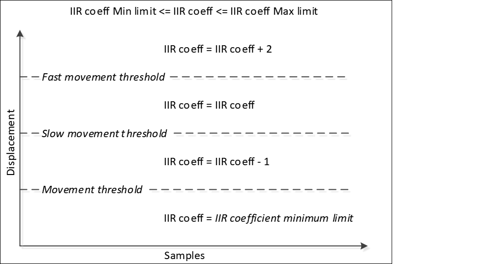
| Adaptive IIR filter | Enables the Adaptive IIR filter – an IIR filter that changes its own IIR coefficient according to the speed of the finger movement. This is done to smooth the fast movement of the finger and at the same time control properly the position movement. The filter coefficients are automatically adjusted by the adaptive algorithm with the speed of the finger movement. If the finger moves slowly, the IIR coefficient decreases; if the finger moves fast, the IIR coefficient increases from the existing value. Consumes 3 bytes of RAM per each position (filter history). |
| Position movement threshold | Defines the position threshold below, whose position displacement is ignored or considered as no movement. |
| Position slow movement threshold | Defines the position threshold below (and the above Position movement threshold), whose position displacement (the difference between the current and previous position) is considered as a slow movement. If the position displacement is within the threshold limits, the IIR filter coefficient decreases during each new scan. So, the filter impact on the position becomes less intensive. |
| Position fast movement threshold | Defines the position threshold above, whose position displacement is considered as a fast movement. If the position displacement is above the threshold limit, the IIR filter impact on the position becomes more intensive during each new scan as the filter coefficient increases. |
| IIR coefficient maximum limit | Defines the maximum limit of the IIR coefficient when the finger moves fast. The fast movement event is defined by the position fast movement threshold. |
| IIR coefficient minimum limit | Defines the minimum limit of the IIR coefficient when the finger moves slowly. The slow movement event is defined by the position slow movement threshold. |
| IIR coefficient divisor | This parameter acts as the scale factor for the filter IIR coefficient. Output = Coeff/Divisor × input + (Divisor-Coeff)/Divisor × previousOutput where: - Input, Output, and Previous Output are the touch positions; - Coeff is the automatically adjusted IIR filter coefficient; - Divisor is the IIR coefficient divisor (this parameter). |
Applicability
| Parameter name | Sensing method/Widget | ||
|---|---|---|---|
| CSD | CSX | ISX | |
| Adaptive IIR filter | Linear Slider Radial Slider Touchpad | Linear Slider Touchpad | N/A |
| Position movement threshold | |||
| Position slow movement threshold | |||
| Position fast movement threshold | |||
| IIR coefficient maximum limit | |||
| IIR coefficient minimum limit | |||
| IIR coefficient divisor | |||
Centroid parameters [all gen]
Description
| Parameter name | Description |
|---|---|
| Centroid type | Selects a sensor matrix size for centroid calculation. The 5x5 centroid (also known as Advanced Centroid) provides benefits such as Two-finger detection, Edge correction and improved accuracy. If Advanced Centroid is selected, the below parameters are configured as well. |
| Enable finger type detection | Enables the finger type detection for sliders. Differentiated between normal fingers, fat fingers, and large objects. The position reporting is limited to normal and fat fingers only. |
| Position noise threshold | The threshold value subtracted from each difference count in the 5-sensor window before centroid calculation for a normal finger. Suppresses noise so only meaningful signals contribute to the position calculation. |
| Outer edge offset | The offset applied to centroid weights when the peak is at the outermost sensors (index 0 or N-1). Improves the position linearity and accuracy at the physical end of the slider. Value range: 0 to 32767. |
| Inner edge offset | The offset applied to centroid weights when the peak is at the inner-edge sensors (index 0 or N-2). Improves the position linearity and ensures the smooth transition between the edge and core regions of the slider. Value range: 0 to 32767. |
| Touch zone width | The multiplier (1/256 units ) applied to the local peak signal to determine the threshold for including neighboring sensors in the touch zone. Higher values narrow the touch zone; lower values widen it. Value range: 0 to 255. |
| Fat finger width | The minimum number of contiguous active sensors in a touch zone required to classify the touch as a fat finger. Value range: 0 to 128. |
| Large object width | The minimum size to detect a large object on the slider. Value range: 0 to 128. |
| Slider centroid multiplying method | Defines the method of the multiplier calculation for Linear Slider widgets. The options: - SNS_NUM_MINUS_1 – The minimum position is in the middle of the first segment, the maximum position is in the middle of the last segment. - SNS_NUM – The minimum position is in the left edge of the first segment, and the maximum position is in the right edge of the first segment. |
| Cross-coupling position threshold | Defines the cross-coupling threshold. This value is subtracted from the sensor signal used for centroid position calculation to improve the accuracy. The threshold should be equal to a sensor signal when a finger is near the sensor but is not touching the sensor. This can be determined by slowly dragging the finger across the panel and finding the inflection point of the difference counts at the base of the curve. The difference value at this point is the Cross-coupling threshold. The default value is 5. |
| Edge correction | This feature is available only for the Centroid Type configured to 5x5. When enabled, a matrix of centroid calculation is updated with virtual sensors on the edges of a Touchpad. It improves the accuracy of the reported position on the edges. When enabled, two more parameters must be configured: Virtual Sensor threshold and Penultimate threshold. |
| Virtual sensor threshold | This parameter is applicable only if Edge correction is enabled and used to calculate a signal (difference count) for a virtual sensor used for the edge correction algorithm. A touch position on a Linear Slider/Radial Slider or Touchpad is calculated using a signal from the local-maxima sensor and its neighboring sensors. A touch on the edge sensor of a Slider or Touchpad does not accurately report a position because the edge sensor lacks signal from one side of neighboring sensors of the local-maxima sensor. 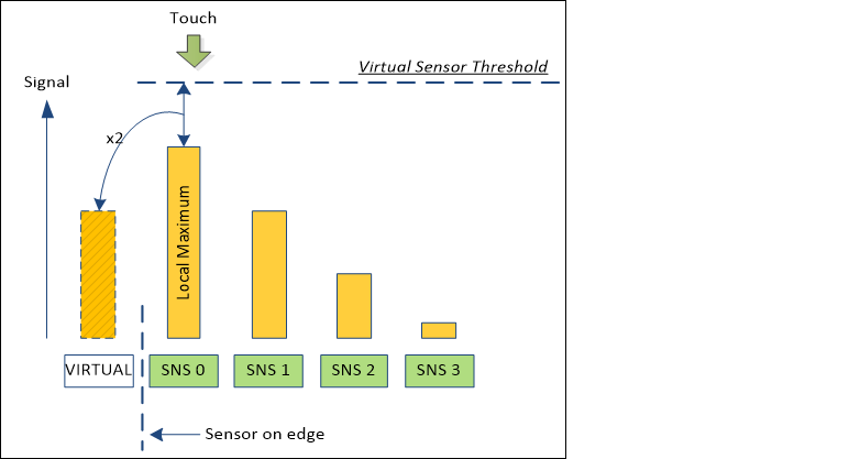 If the Edge correction is enabled, the algorithm adds a virtual neighbor sensor to correct the deviation in the reported position. The Virtual sensor signal is defined by the Virtual sensor threshold: DiffCountvirtual = (Thresholdvirtual - DiffCountsns0) × 2 where: - DiffCount VIRTUAL is the virtual sensor difference count; - Threshold VIRTUAL is the virtual sensor threshold; - DiffCount SNS0 is the sensor 0 difference count. The conditions for a virtual sensor (and Edge correction algorithm) to be applied: - Local-maxima is detected on the edge sensor - The difference count from the penultimate sensor is less than the Penultimate threshold. |
| Penultimate threshold | This parameter is applicable only if the Edge correction is enabled and it works along with the Virtual sensor threshold parameter. This parameter defines the threshold of penultimate sensor signal. If the signal from penultimate sensor is below the Penultimate threshold, the edge correction algorithm is applied to the centroid calculation. The conditions for the edge correction to be applied: - Local-maxima is detected on the edge sensor - The difference count from the penultimate sensor (SNS 1 in the image below) is less than the Penultimate threshold. 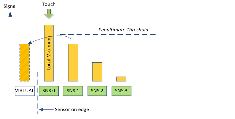 |
| Pseudo two-finger detection | Enables the detection of the second finger on a CSD touchpad. In general, the CSD Touchpad can detect only one true touch position. The CSD Touchpad widget consists of two Linear Sliders and each slider reports the X and Y coordinates of a finger touch. If there are two touches on the Touchpad, there are four possible touch positions as the graph displays. The two of these touches are real touches and two are known as "ghost" touches. There is no possibility to differentiate between ghost and real touches in a CSD widget (to get true multi-touch performance, use the CSX Touchpad widget). 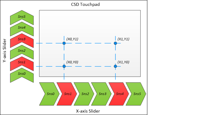 But, if this feature is enabled, the CSD Touchpad can report up to two touches, mainly to be used in conjunction with two-finger gestures where real and "ghost" touches do not need to be fully differentiated. It is available for the CSD Touchpad only with the Centroid type configured to 5x5. The Advanced Centroid (Centroid type is 5x5) uses the 3x3 centroid matrix when detects two touches. |
Applicability
| Parameter name | Sensing method/Widget | ||
|---|---|---|---|
| CSD | CSX | ISX | |
| Centroid type | Touchpad Linear Slider | N/A | |
| Cross-coupling position threshold | |||
| Edge correction | |||
| Virtual sensor threshold | |||
| Penultimate threshold | |||
| Pseudo two-finger detection | |||
Ballistic multiplier parameters [all gen]
Description
| Parameter name | Description |
|---|---|
| Ballistic multiplier | Enables the Ballistic multiplier filter used to provide better user experience of the pointer movement. Fast movement will increase the position more quickly. Consumes 16 bytes of RAM when enabled. The simplified diagram of the Ballistic Multiplier filter operation: 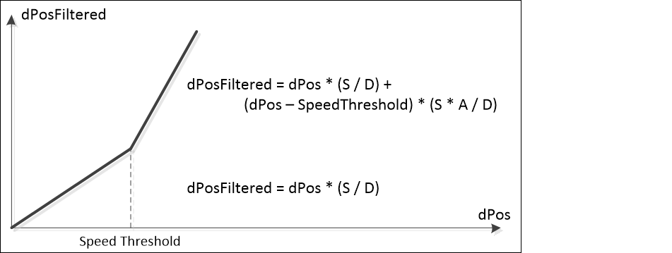 where, - dPos – an input position displacement either in the X axis or Y axis, - dPosFiltered – the filtered displacement; - SpeedThreshold – either the X-axis speed threshold or Y-axis speed threshold; - A – the Acceleration coefficient; - S – the Speed coefficient; - D – the Divisor value. |
| Acceleration coefficient | Defines the value at which the position movement needs to be interpolated when the movement is classified as fast movement. The reported position displacement is multiplied by this parameter. |
| Speed coefficient | Defines the value at which the position movement is interpolated when the movement is classified as slow movement. The reported position displacement is multiplied by this parameter. |
| Divisor value | Defines the divisor value used to create a fraction for the acceleration and speed coefficients. The interpolated position coordinates are divided by the value of this parameter. |
| X-axis speed threshold | Defines the threshold to distinguish fast and slow movement on the X axis. If the X-axis position displacement reported between two consecutive scans exceeds this threshold, then it is considered as fast movement, otherwise as slow movement. |
| Y-axis speed threshold | Defines the threshold to distinguish fast and slow movement on the Y axis. If the Y-axis position displacement reported between two consecutive scans exceeds this threshold, then it is considered as fast movement, otherwise as slow movement. |
Applicability
| Parameter name | Sensing method/Widget | ||
|---|---|---|---|
| CSD | CSX | ISX | |
| Ballistic multiplier | Touchpad | N/A | |
| Acceleration coefficient | |||
| Speed coefficient | |||
| Divisor value | |||
| X-axis speed threshold | |||
| Y-axis speed threshold | |||
Gesture parameters
A gesture consists of a sequence of Touchdown and Lift Off events.
| Gesture event | Description |
|---|---|
| Touchdown | A simple touch on a widget. |
| Lift Off | A removal of a finger from a widget. If the Lift Off event triggers another higher-level gesture, the Lift Off event is not reported. |
The limitation for widgets that consist multiple independent sensors, for example, Ganged Buttons and Matrix Buttons:
The one-finger click gestures (Single click, Double click, Long Press) are limited for detection by a touch on a single sensor. When multiple sensors within a widget are touched simultaneously, the gesture detection may not function properly and produce incorrect detection of a double click.
Gesture parameters [all gen]
Description
| Parameter | Description |
|---|---|
| Enable gestures | The Master enable for the gestures feature. |
| Enable one-finger single click gestures | A combination of Touchdown and Lift Off events under specific conditions: - A Touchdown event is followed by a Lift Off event. - The touch duration (between Touchdown and Lift Off) is greater than the Minimum click timeout and less than the Maximum click timeout . - Position displacements between the Touchdown and Lift Off events must be within the Maximum click distance . 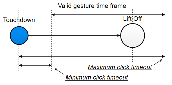 |
| Enable one-finger double click gestures | A combination of two sequential one-finger single click gestures under specific conditions: - Both clicks in the sequence must meet one-finger single click conditions. - The touch duration between two Touchdown events must be within the Minimum second click interval and Maximum second click interval timeout limits. - The distance between two clicks must not exceed the Maximum second click distance . 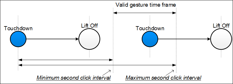 |
| Enable one-finger triple click gestures | A combination of three sequential one-finger single click gestures under specific conditions (the one-finger single click conditions): - The touch duration between two Touchdown events must be within the Minimum second click interval and Maximum second click interval timeout limit. - The distance between clicks must not exceed the Maximum second click distance . 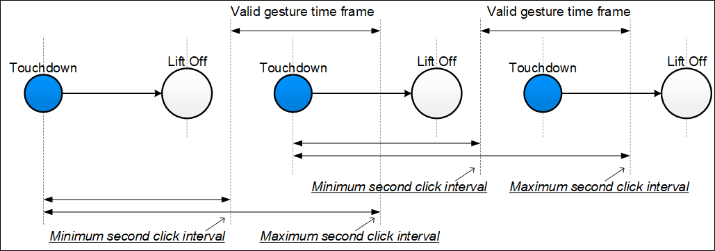 |
| Enable one-finger long press gestures | A Touchdown event under specific conditions: - The touch duration must be greater than Minimum long press timeout . - Position displacements must be within the Maximum click distance . Note: This option is supported by CAPSENSE™ Middleware 4.0 and later. |
| Enable two-finger long press gestures | The design is the same as the one-finger long press under specific conditions: - There must be two simultaneous finger touches detected on a widget for a long press to be considered as a two-finger long press. |
| Enable one-finger click & drag gestures | This gesture is a one-finger click and a hold followed by a drag. A typical use case is while moving items on the screen from one point to another. The gesture is triggered when the finger movement follows this sequence: Touchdown → Lift Off → Touchdown → Drag. The gesture triggers under specific conditions: - A one-finger click gesture and a subsequent Touchdown are detected within the Minimum click timeout and Maximum click timeout limits and within Maximum second click distance . - The finger exceeds the Maximum click distance from a drag touchdown. 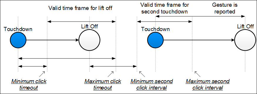 |
| Enable two-finger single click gestures | A two-finger single click gesture is a combination of Touchdown and Lift Off events under specific conditions: - Two simultaneous finger touches (Touchdown and Lift Off) are detected. - The duration between the second finger Touchdown and Lift Off events of both fingers must be within the Minimum second click interval and Maximum second click interval timeout limits. - The duration counting starts when the settling time elapsed for the second finger Touchdown event. - A position displacement between the Touchdown and Lift Off events is less than the Maximum second click distance . 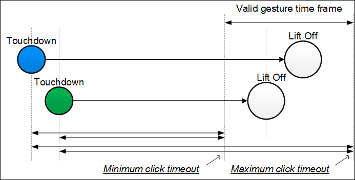 |
| Enable two-finger double click gestures | The design is the same as of the one-finger long press under specific conditions: - There must be two simultaneous finger touches detected on a widget for a long press to be considered as a two-finger long press. 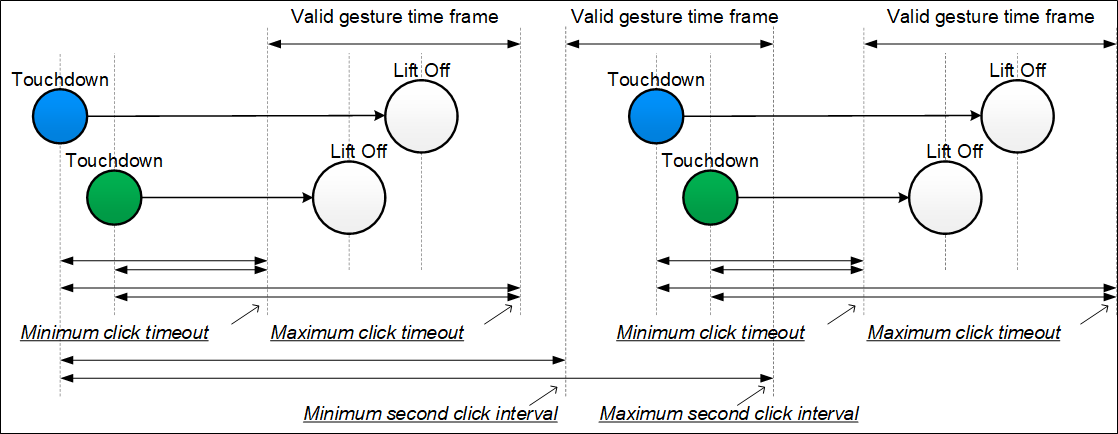 |
| Enable one-finger scroll gestures | The one-finger scroll gesture is a combination of a Touchdown followed by a displacement in a specific direction under specific conditions: - For a slider, the position displacement between two consecutive scans must exceed the Minimum scroll distance . - The scroll debounce number of a scroll gesture in the same direction is already detected. 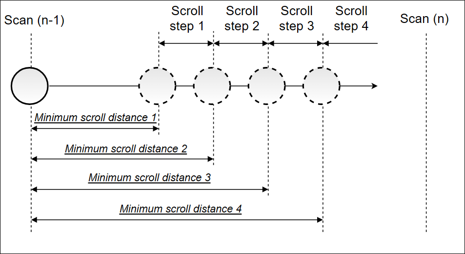 |
| Enable two-finger scroll gestures | The design of the two-finger scroll gesture is the same as of the one-finger scroll under specific conditions: - There must be two simultaneous finger touches detected on a widget for a scroll to be considered as a two-finger scroll. - The displacement of both finger touches must be on the same direction. |
| Enable one-finger edge swipe gestures | The edge swipe gesture is a combination of a Touchdown on an edge followed by a displacement towards the center. This gesture works under specific conditions: - A Touchdown event must occur in the edge area defined by the Edge size . - A finger displacement must occur from the edge towards the center within the Maximum edge angle . - The displacement must exceed the Minimum edge distance within the Maximum edge timeout duration. 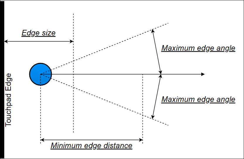 |
| Enable two-finger edge swipe gestures | The design of the two-finger edge swipe gesture is the same as of the one-finger edge swipe under specific conditions: - There must be two simultaneous finger touches detected on a widget for an edge swipe to be considered as a two-finger edge swipe. - The displacement of both finger touches must be on the same direction. 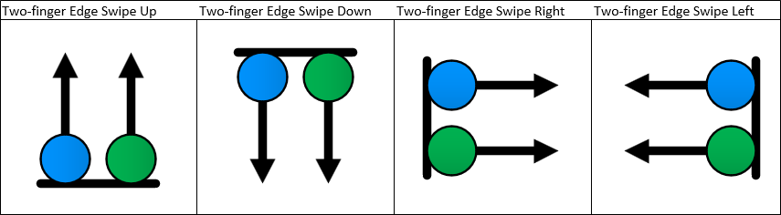 |
| Enable one-finger flick gestures | A flick gesture is a combination of a Touchdown followed by a high-speed displacement and a Lift Off event. A flick gesture starts at a Touchdown and completes and reported at a Lift Off event. This gesture works under specific conditions: - The displacement must exceed the Minimum flick distance . - The duration between a Touchdown and Lift Off events must be less than the Maximum flick timeout . 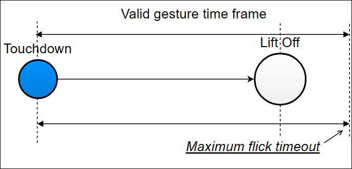 Note: The flick gesture is detected in 8 directions: Up; Down; Left; Right; Up-Right; Down-Left; Up-Left; Down-Right |
| Enable two-finger flick gestures | The design is the same as of the one-finger flick under specific conditions: - There must be two simultaneous finger touches detected on a widget for a flick to be considered as a two-finger flick. - The displacement of both finger touches must be on the same direction. 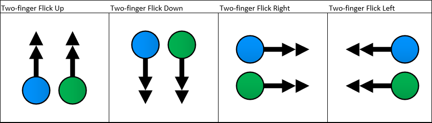 |
| Enable one-finger rotate gestures | A one-finger rotate gesture is reported when a circular displacement is detected. The decoding algorithm uses four directions to identify a circular displacement. This gesture works under specific conditions: - A displacement in all four directions must be in the succession order to report a rotate gesture. - The rotation direction can be clockwise or counter-clockwise. 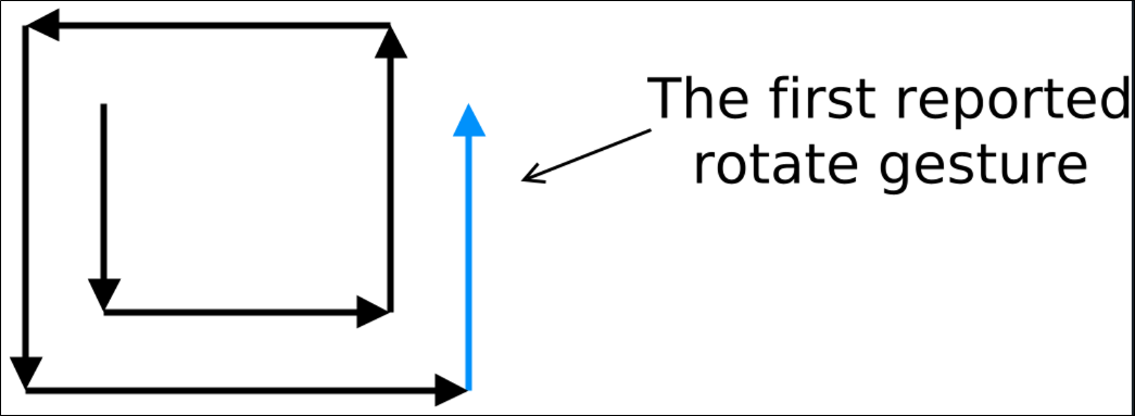 |
| Enable two-finger zoom gestures | A two-finger zoom gesture is reported when two touches move towards each other (Zoom Out) or move away from each other (Zoom In). This gesture works under specific conditions: - An increase or decrease in distance between two-finger touch positions must exceed the Minimum zoom distance . - The zoom debounce number of a Zoom In or Zoom Out gesture must be sequentially detected to report a zoom gesture. - A scroll to the zoom debounce number of a zoom gestures must be sequentially detected to report a zoom gesture. If a zoom gesture occurs after a scroll, the gesture is reported and there was no Lift Off event between the scroll and Zoom gestures. |
| Enable gesture filtering | Enables filtering of the detected gestures. The gesture priority is defined as follows (starting from the most important): Two-finger zoom; Two-finger scroll; One-finger rotate; One-finger edge swipe; One-finger flick; One-finger scroll; Two-finger single click; One-finger click & drag; One-finger double click; One-finger single click; Touchdown; Lift Off. |
Applicability
| Parameter name | Sensing method/Widget | ||
|---|---|---|---|
| CSD | CSX | ISX | |
| Enable gestures | Button Linear Slider Radial Slider Matrix Buttons Touchpad | Button Linear Slider Matrix Buttons Touchpad | Button Linear Slider |
| Enable one-finger single click gestures | |||
| Enable one-finger double click gesture | |||
| Enable one-finger triple click gestures | Button Linear Slider Radial Slider Matrix Buttons Touchpad | Button Linear Slider Matrix Buttons Touchpad | Button Linear Slider |
| Enable one-finger long press gestures | Button Linear Slider Radial Slider Matrix Buttons Touchpad | Button Linear Slider Matrix Buttons Touchpad | Button Linear Slider |
| Enable two-finger long press gestures | Touchpad | N/A | |
| Enable one-finger click & drag gestures | Linear Slider Touchpad | Linear Slider | |
| Enable two-finger single click gestures | Touchpad | N/A | |
| Enable two-finger double click gestures | |||
| Enable one-finger scroll gestures | Linear Slider Touchpad | Linear Slider | |
| Enable two-finger scroll gestures | Touchpad | N/A | |
| Enable one-finger edge swipe gestures | |||
| Enable two-finger edge swipe gestures | |||
| Enable one-finger flick gestures | Linear Slider Touchpad | Linear Slider | |
| Enable two-finger flick gestures | Touchpad | N/A | |
| Enable one-finger rotate gestures | |||
| Enable two-finger zoom gestures | |||
| Enable gesture filtering | Button Linear Slider Radial Slider Matrix Buttons Touchpad | Button Linear Slider Matrix Buttons Touchpad | Button Linear Slider |
Gesture report parameters
| Parameter | Description |
|---|---|
| Maximum click timeout | Defines the maximum duration between a Touchdown and Lift Off events of a click event. This parameter is used in all click-based gestures. |
| Minimum click timeout | Defines the minimum duration between a Touchdown and Lift Off events of a click event. This parameter is used in all click-based gestures. |
| Maximum click distance | Defines the maximum displacement between a Touchdown and Lift Off events of a click event. This parameter is used in all click-based gestures. |
| Maximum second click interval | Defines the maximum displacement between a Touchdown and Lift Off events of a click event. This parameter is used in all click-based gestures. |
| Minimum second click interval | This parameter defines the minimum duration between the first Lift Off and the second Touchdown events. If the second click occurs early this limit, the double-click and click & drag gestures are not reported. |
| Maximum second click distance | Defines the maximum distance between the first Lift Off event and the second Touchdown event. If the second click occurs outside this limit, the double-click and click & drag gestures are not reported. |
| Minimum long press timeout | Defines the minimum duration after a touchdown event and before a lift off event of a long press event. |
| Maximum long press distance | Defines the maximum displacement to be detected for a long press to be valid. |
| Scroll debounce | Defines the minimum number sequential scroll steps in the same direction to be detected prior to the scroll is considered valid. A widget must detect scroll steps, at the minimum of Debounce times in the same direction to be considered as a scroll in that direction. |
| Minimum scroll distance | Defines the minimum displacement to recognize a single scroll step. A scroll step is calculated between two consecutive scans. |
| Rotate debounce | Defines the maximum number of sequential rotate steps in the same direction to deem a rotate gesture invalid. For example, if the Debounce value is set to 5, then the touch cannot continue in the same direction for 5 rotate steps and still have a valid rotate gesture. After this threshold, the reported gesture stops being a rotate gesture. If this parameter is set to 0, then the Debounce is disabled. |
| Minimum rotate distance | Defines the minimum displacement to recognize a single rotate step. |
| Zoom debounce | Defines the minimum number of zoom steps in a particular direction (in or out) to report a zoom gesture. |
| Minimum zoom distance | Defines the minimum displacement to recognize a single zoom step. |
| Maximum flick timeout | Defines the maximum duration of how long a flick gesture is searched after a Touchdown event. A position displacement and Lift Off event must happen within the duration defined by this parameter for a flick to be valid. |
| Minimum flick distance | Defines the minimum displacement to be detected for a one-finger flick to be valid. |
| Edge size | Defines the maximum edge area where a Touchdown must be detected for an edge swipe to be reported. |
| Minimum edge distance | Defines the minimum displacement to be detected from an edge to the center for an edge swipe to be reported. |
| Maximum edge timeout | Defines the maximum duration, within which an edge swipe must occur to be reported. The displacement must exceed the displacement threshold within the duration defined by this parameter for the edge swipe to be reported. |
| Maximum edge angle | To report this gesture, a finger movement starts from an edge and moves in the center direction. This is the ideal line. These parameters define the maximum angle deviation (in degree) from this ideal line for the edge swipe to be valid. Degree 1 means that the user can do gestures only on a single ideal line. |
Gesture/Gesture report parameters table
| Gesture parameter | Gesture report parameters | |||||||||||||||||||
|---|---|---|---|---|---|---|---|---|---|---|---|---|---|---|---|---|---|---|---|---|
| Maximum click timeout | Minimum click timeout | Maximum click distance | Maximum second click interval | Minimum second click interval | Maximum second click distance | Minimum long press timeout | Maximum long press distance | Scroll debounce | Minimum scroll distance | Rotate debounce | Minimum rotate distance | Zoom debounce | Minimum zoom distance | Maximum flick timeout | Minimum flick distance | Edge size | Minimum edge distance | Maximum edge timeout | Maximum edge angle | |
| One-finger single click | √ | √ | √ | |||||||||||||||||
| One-finger double click | √ | √ | √ | √ | √ | √ | ||||||||||||||
| One-finger long press | √ | √ | ||||||||||||||||||
| One-finger click & drag | √ | √ | √ | √ | √ | √ | ||||||||||||||
| Two-finger single click | √ | √ | √ | |||||||||||||||||
| One-finger scroll | √ | √ | ||||||||||||||||||
| Two-finger scroll | √ | √ | ||||||||||||||||||
| One-finger edge swipe | √ | √ | √ | √ | ||||||||||||||||
| One-finger flick | √ | √ | ||||||||||||||||||
| One-finger rotate | √ | √ | ||||||||||||||||||
| Two-finger zoom | √ | √ | ||||||||||||||||||
| One-finger triple click | √ | √ | √ | √ | √ | √ | ||||||||||||||
| Two-finger double click | √ | √ | √ | √ | √ | √ | ||||||||||||||
| Two-finger long press | √ | √ | ||||||||||||||||||
| Two-finger edge swipe | √ | √ | √ | √ | ||||||||||||||||
| Two-finger flick | √ | √ | ||||||||||||||||||
Sensor parameters [various gen]
Description
| Parameter name | Description | CAPSENSE™ generation | ||
|---|---|---|---|---|
| 5th LP | 5th | 4th | ||
| Compensation IDAC value(s) | Sets the Compensation IDAC value for each sensor/node when Enable compensation IDAC value is selected on the CSD Settings tab. For CSD sensing method (see ), a higher Compensation IDAC value without saturating raw counts provides better sensitivity for sensor/nodes. Select the Enable IDAC auto-calibration for robust operation. Widget Sensing Method [all gen] | √ | ||
| Compensation CDAC value(s) | Sets the Compensation CDAC value for each sensor/node when Enable compensation CDAC is selected on the CSX Settings tabs. For CSX sensing method (see Widget Sensing Method [all gen]), a higher Compensation CDAC value without saturating raw counts provides better sensitivity for sensor/nodes. Select the Enable CDAC auto-calibration for robust operation. | √ | √ | |
| Selected pins | Selects a port pin for the sensor (CSD sensing) and electrode (CSX sensing). The available options use a dedicated pin for a sensor or re-use one or more pins from any other sensor. Re-using the pins of any other sensor from any widgets helps create a ganged sensor. | √ | ||
Applicability
| Parameter name | CAPSENSE™ generation | Sensing method/Widget | ||||
|---|---|---|---|---|---|---|
| 5th LP | 5th | 4th | CSD | CSX | ISX | |
| Compensation IDAC value(s) | √ | Button Linear Slider Radial Slider Matrix Buttons Touchpad Proximity | Button Linear Slider Matrix Buttons Touchpad | N/A | ||
| Compensation CDAC value(s) | √ | √ | √ | Button Linear Slider Radial Slider Proximity Low Power | Button Linear Slider Matrix Buttons Touchpad Low Power | Button Linear Slider Low Power |
| Selected pins | √ | Button Linear Slider Radial Slider Matrix Buttons Touchpad Proximity | Button Linear Slider Matrix Buttons Touchpad | N/A | ||
Footnotes
-
[various gen] means certain sections apply differently to various CAPSENSE™ generations. ↩