Creating a new symbol
New symbols are created by clicking the New Symbol button.
About this task
Symbols are graphical representations of components in the schematic editor. Create a new symbol when you want to create a new local component for use in schematics or when you need a different representation for an existing local component.
If you want to create a new local component, note that a matching model in a library contained in the same project is required in addition to the symbol. If you create a local component, you can automatically create a symbol for a model in your project. (See
Creating a local component
.)
Procedure
Select the project to which you want to add a symbol and click the

button in the
Workspace
widget.
You can also right-click the project and choose
New Symbol
from the context menu.
The
New Symbol
dialog opens.
Enter a name for the new symbol and click OK.

The symbol file appears in your workspace and the symbol editor opens with the new file ready for editing.
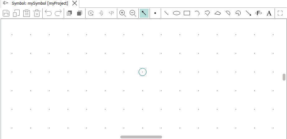
The circle in the drawing area indicates the location that will placed where you click the mouse when using the symbol. Usually, it is best to draw the symbol so that this circle is at the center of the symbol.
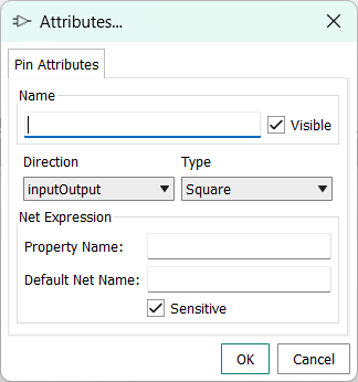
Place the pins for the component that the symbol will represent.
Choose the Set Pin tool (
 )
.
)
.The Attributes dialog opens.
For example:

Draw the desired symbol using the graphics tools at the right of the toolbar.
The tools work similar to the tools available in common graphics applications. Note that each tool remains selected until you select another tool or press Esc.
You can reposition the pins during this process. If you do so, make sure that the default grid is still active and that
Snap to Grid
is switched on to avoid misalignment issues wen using the local component.
For example:

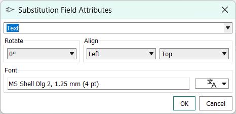
- If desired, place text or placeholders for component properties in the symbol
using the Substitution Field
 tool.
tool.Depending on the type of label you specify, the text is either displayed verbatim or replaced with the actual values of a property when the local component is placed in a schematic.
Click the
tool.
The
Substitution Field Attributes
dialog opens.
What to do next
Use the symbol to create a local component as described in
Creating a local component
.