Creating a local component
Local components are custom parts that you can use in schematics. They are a combination of a netlist subcircuit and a symbol.
About this task
To create local component, its subcircuit must be described in the netlist of a library that is contained in the project. A symbol is also required, which can be created before or during the creation of the local component.
The content and structure of
InfineonSpice
libraries follows standard SPICE conventions, as described in
Working with libraries
. The description of these conventions is beyond the scope of this manual. However, you can find detailed information about it in Infineon’s Titan reference manual and other generally available sources.
Before you begin
The component’s description must be available as a subcircuit in a library in the project. You can make it available by adding it to the library manually or by importing a library containing the description. For more information, see Working with libraries .
If you do not want to create the symbol during the process (as described below), the symbol must be contained in the library. For information on creating symbols, see Working with symbols .
Procedure
In the
Workspace
view, select the desired project and click the

button.
You can also choose
or right-click the project and choose
New Local Component
from the context menu.
The
New Device
dialog opens.
Click
Default
.
The
Symbol Library
dialog opens.
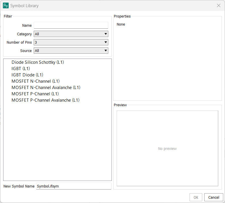
In the list of symbols, select the symbol that you want to use for the new component.
You can filter the list by entering part of the symbol name in the
Name
field, by choosing the desired category, the number of pins, or the source. If you specify multiple filter criteria, only symbols that match all of them are displayed.
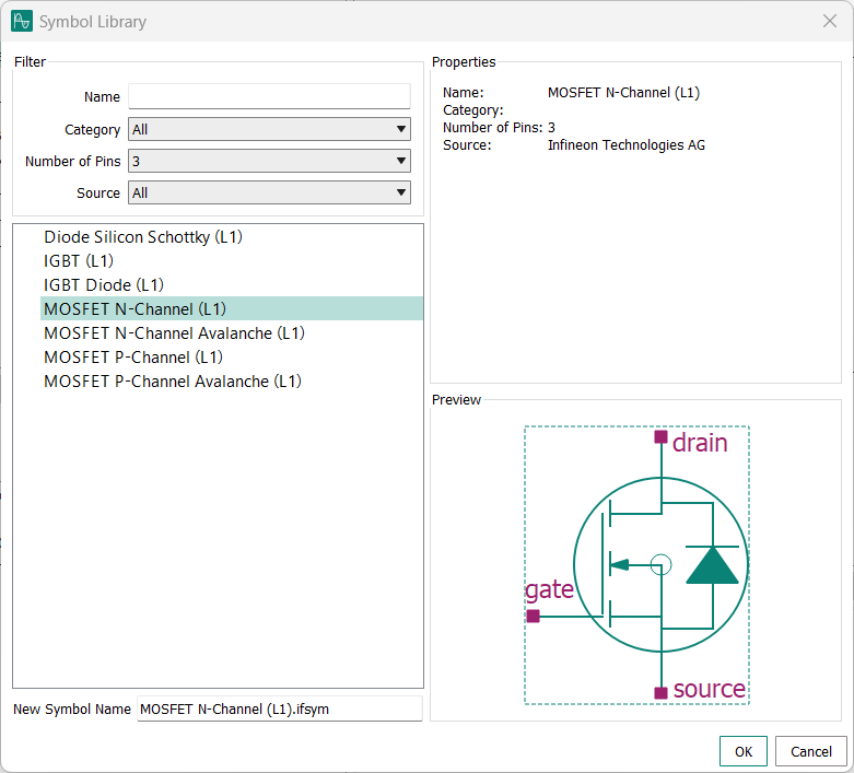
Enter a name for the new symbol and click
OK
.
The
Symbol Generation Options
dialog opens.
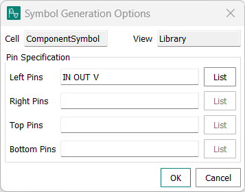
All pin names defined by the model are listed in the
Left Pins
field, meaning that those pins will be positioned at the left edge of the generated symbol.
Results
The new custom component is available in the project folder and can be used in schematics.
Note that you cannot edit the local component itself, but you can edit its symbol and its model separately using, respectively, the Open in Symbol Editor and
Open in Text Editor
context menu commands in the
Workspace
view.