PSOC™ Edge E84 multi-core application
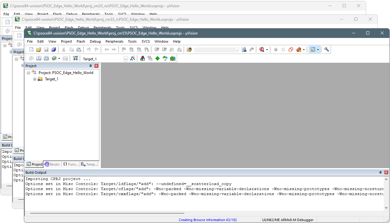
After creating all three projects as described in Create Keil µVision project(s). When complete, you should have three project instances of Keil µVision open like the following image. Then, follow the instructions in this section to configure, build, program, and debug the application.
Configure and build multi-core projects
Once all projects are open, configure and build the secure CM33, non-secure CM33, and CM55 projects in sequential order. Because they are separate projects that depend on each other, the postbuild process will fail for the first two projects, but then will succeed on the third project.
Secure CM33 project
-
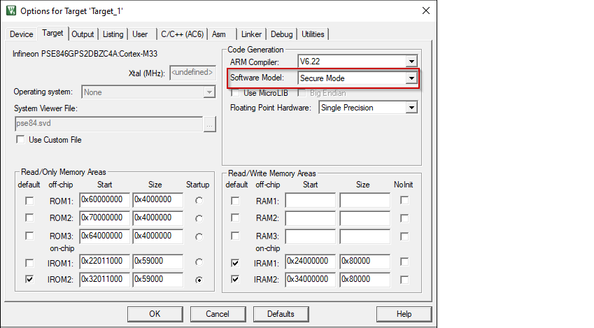
Open the Options dialog. Go to the Target tab and select "Secure Mode" for Software model .
-
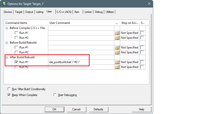
Switch to the User tab, enable the Run #1 check box located under After Build/Rebuild . Then, paste the following command as single line (edit paths as needed).
ide_postbuild.bat \"#L\"
- Select Project > Build Target to build the project.
This will generate an object file that needs to be referenced in the non-secure project in the next set of steps.
The postbuild will fail with a message like:
: E : ERROR : File not found: "C:\examples\edge-uvision\PSOC_Edge_Hello_World\build\project_hex\proj_cm33_ns.hex". Check the log for details
Proceed to the next step to configure the cm33_ns project.
Non-secure CM33 project
-
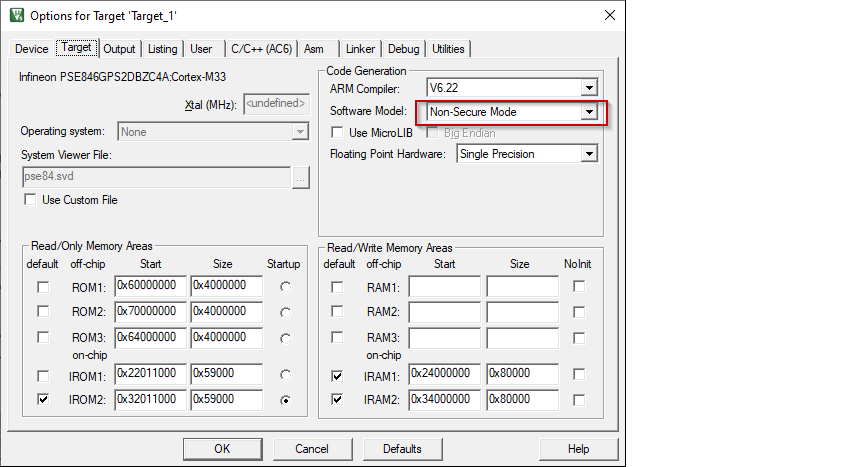
Open the Options dialog. Go to the Target tab and select "Non-Secure Mode" for Software model .
-
Switch to the User tab and enable the Run #1 check box located under After Build/Rebuild . Then, paste the following command as single line (edit paths as needed).
ide_postbuild.bat \"#L\"
-
Click OK to close the Options dialog.
-
Select Project > Build Target to build the project.
The postbuild will fail with a message like:
: E : ERROR : File not found: "C:\examples\edge-uvision\PSOC_Edge_Hello_World\build\project_hex\proj_cm55.hex". Check the log for details
Proceed to the next step to configure the cm55 project.
CM55 project
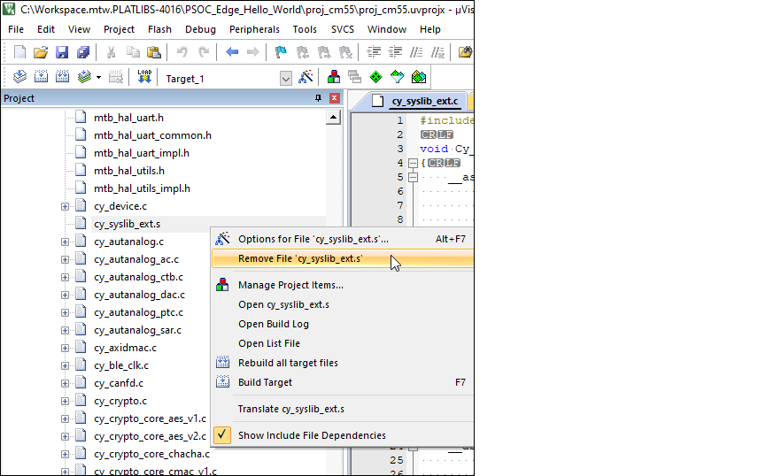
The default CM55 project includes a cy_syslib_ext.s that is not compatible with µVision, and the file needs to replaced with a .c file
-
Select the project window and locate the file cy_syslib_ext.s under the Target_1 > mtb-dsl-pse8xxgp in the project tree. Right-click on it and select Remove File 'cy_syslib_ext.s '.
Note: In some older versions of µVision, there is only one folder named '[unnamed]'.
-
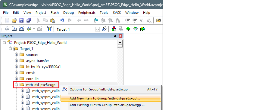
Right click on the mtb-dsl-pse8xxgp group and select Add New Item to Group '[name]' …
-
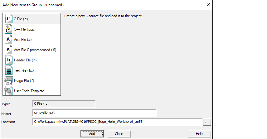
Then, choose a new C source file, specify the name "cy_syslib_ext", and click the Add button.
-
Copy the following code and paste it into the newly created file named "cy_syslib_ext.c".
    #include <stdint.h>

    void Cy_SysLib_DelayCycles(uint32_t cycles)
    {
        __asm volatile (
            "adds %0, %0, #2 \n"           // Add 2 to cycles
            "lsrs %0, %0, #2 \n"           // Logical Shift Right by 2 (divide by 4)
            "beq Cy_DelayCycles_done \n"   // Branch to done if cycles is zero

            "Cy_DelayCycles_loop: \n"      // Label for loop start
            "adds %0, %0, #1 \n"           // Increment cycles
            "subs %0, %0, #2 \n"           // Subtract 2 from cycles
            "bne Cy_DelayCycles_loop \n"   // Branch to loop if cycles is not zero

            "Cy_DelayCycles_done: \n"      // Label for loop end
            : "+r" (cycles)                // Output operand
        );

    }

    uint32_t Cy_SysLib_EnterCriticalSection(void)
    {
        uint32_t primask;
        __asm volatile(
            "mrs %0, primask\n"    // Save and return interrupt state
            "cpsid i"              // Disable interrupts
            : "=r" (primask)       // Output to 'primask'
            :
            : "memory"
        );
        return primask;
    }

    void Cy_SysLib_ExitCriticalSection(uint32_t savedIntrStatus)
    {
        __asm volatile(
            "msr primask, %0"      // Restore interrupt state
            :
            : "r" (savedIntrStatus) // Input from 'savedIntrStatus'
            : "memory"
        );
    }
-
Save the file.
-
Open the Options dialog. Under the User tab, enable the Run #1 check box located under After Build/Rebuild . Then, paste the following command as single line.
ide_postbuild.bat \"#L\"
-
Click OK to close the Options dialog.
-
Select Project > Build Target to build the project and execute post-build commands.
This time, the postbuild will succeed, and you'll see messages similar to the following:
: E : INFO  : metadata_proj_cm33_s: command "sign" validation succeeded
: E : INFO  : Image saved to 'C:\examples\edge-uvision\PSOC_Edge_Hello_World\build\project_hex\proj_cm33_s_signed.hex'
: E : INFO  : metadata_proj_cm33_s: command "sign" succeeded
: E : INFO  : relocate_proj_cm33_ns: command "hex-relocate" validation succeeded
: E : INFO  : Relocating segment 0x08340400-0x08344100 to 0x60340400-0x60344100
: E : INFO  : Saved file to '../build/project_hex/proj_cm33_ns_shifted.hex'
: E : INFO  : relocate_proj_cm33_ns: command "hex-relocate" succeeded
: E : INFO  : merge: command "merge" validation succeeded
: E : INFO  : merge: command "merge" succeeded
Searching installed tools in progress...
Searching installed tools complete
C:\examples\edge-uvision\PSOC_Edge_Hello_World\proj_cm55>ENDLOCAL
".\PSOC_Edge_Hello_World_Objects\PSOC_Edge_Hello_World.axf" - 0 Error(s), 39 Warning(s).
Build Time Elapsed:  00:01:02
Debugger configuration
Next, configure projects to launch multi-core debugging.
Secure CM33 project
-
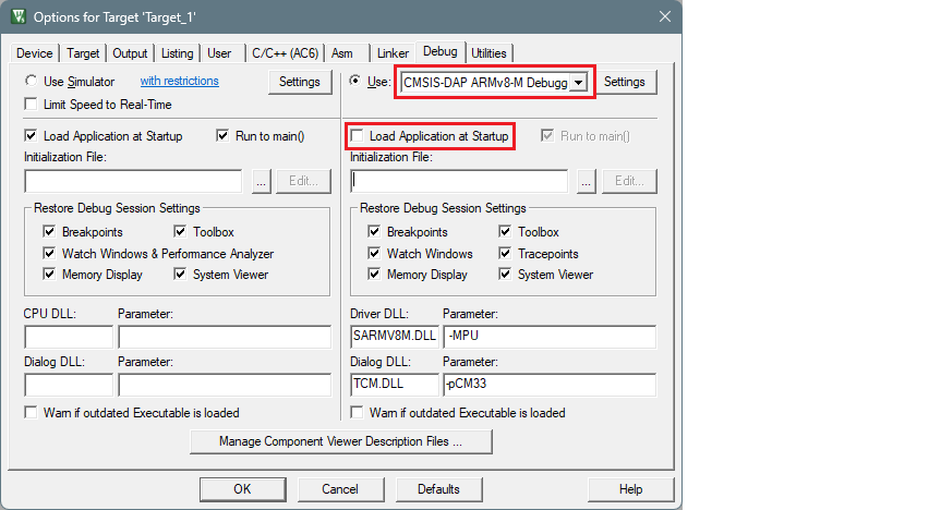
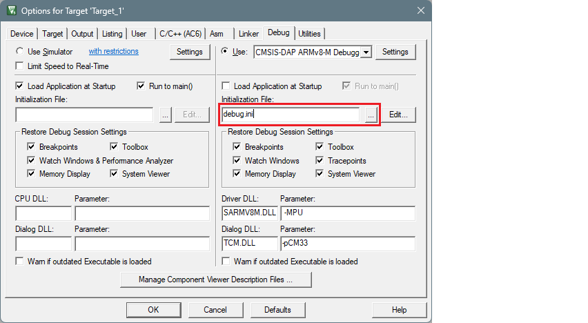
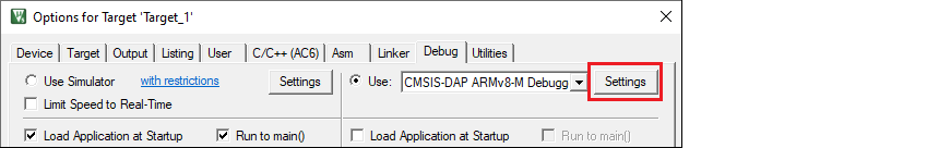
Open the Options dialog. Select the Debug tab and select the applicable debug probe (CMSIS-DAP or J-Link). Make sure that the Load Application at Startup check box is not selected.
-
Select the debug.ini file in the Initialization File field.
-
Click the Settings button to configure the target driver.
-
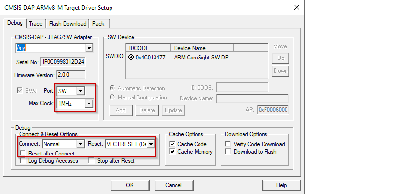
Select the Debug tab, and choose applicable connection options, the configuration settings are different for CMSIS-DAP and J-Link. Refer to the following sections for the applicable options:
CMSIS-DAP/ULINK2 Target Driver Setup
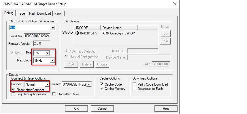
Use the following options:
-
Port : SW
-
Max Clock : 1 MHz
-
Connect : Normal
-
Reset after Connect : selected
-
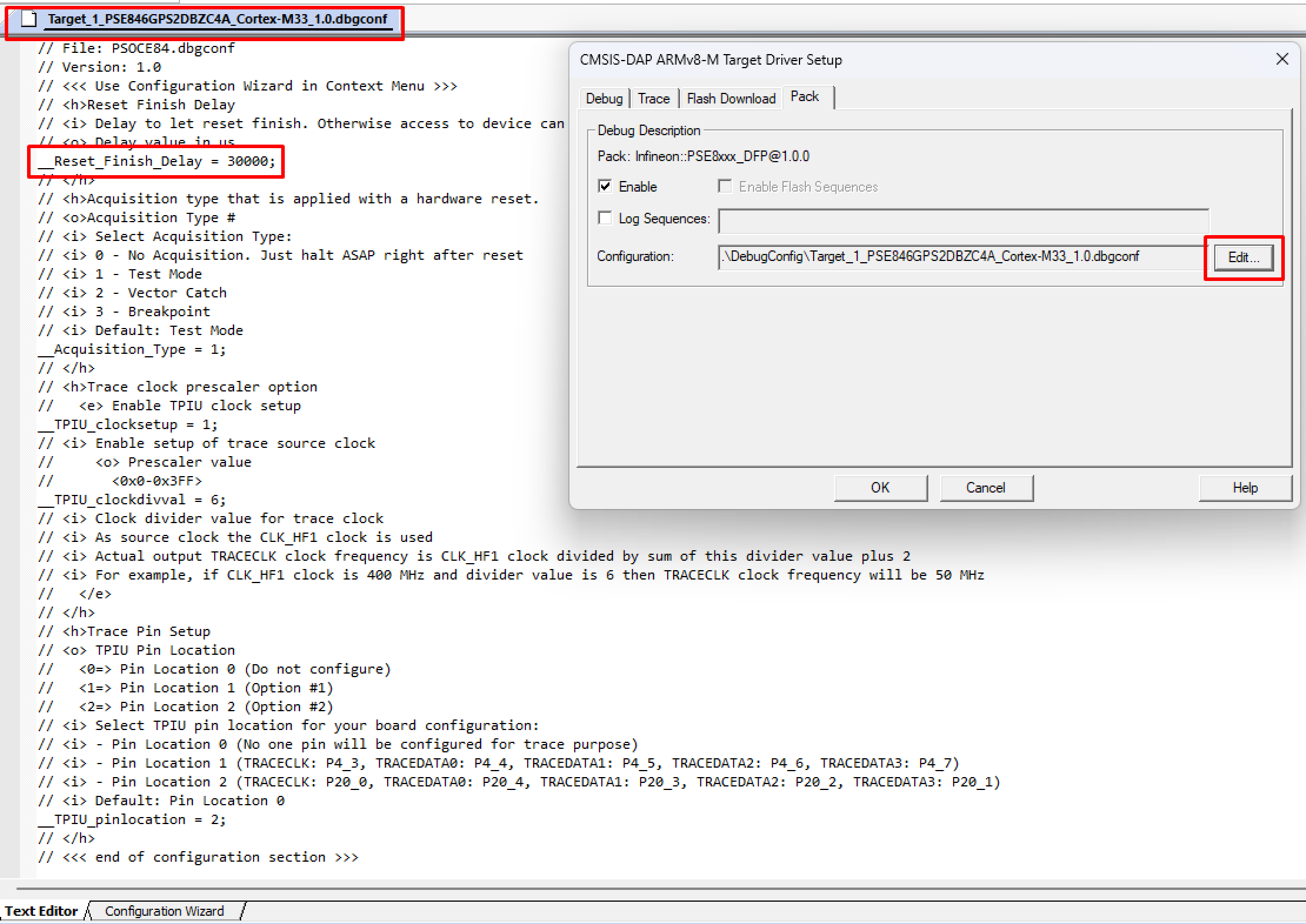
Select desired Reset type. For PSOC™ Edge devices, there are two main reset types available: hardware reset using XRES and system reset by SYSRESETREQ. - For SYSRESETREQ the Vector Catch method is applied. The default reset type is SYSRESETREQ.
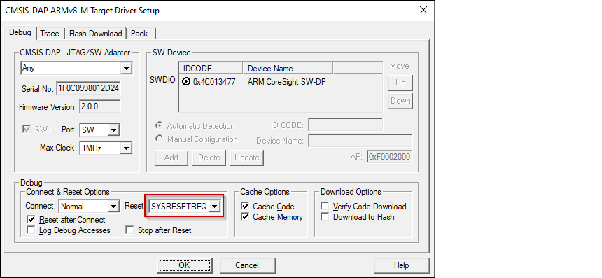
- For XRES additional follow-up acquisition methods are available, including Test Mode acquisition, Vector Catch, and Break Point acquisition (an alternative acquire).
The method to use is determined by the __Acquisition_Type debug variable. The debug variables are accessible for editing at tab Pack clicking Edit button.

By default, the Test Mode acquisition is applied after XRES.
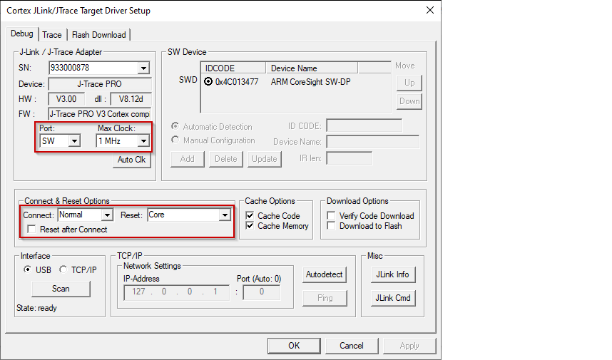
J-Link Target Driver Setup
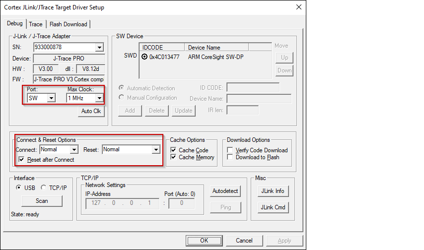
Use the following options:
-
Port : SW
-
Max Clock : 1 MHz
-
Connect : Normal
-
Reset : Normal
-
Reset after Connect : selected
-
-
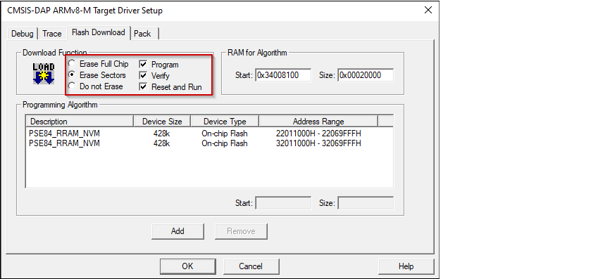
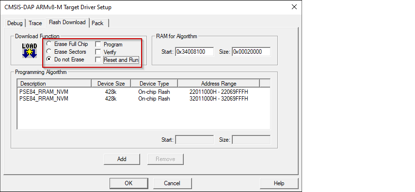
For either driver, switch to the Flash Download tab and select Erase Sectors radio button, as well as Program , Verify , and Reset and Run check boxes.
-
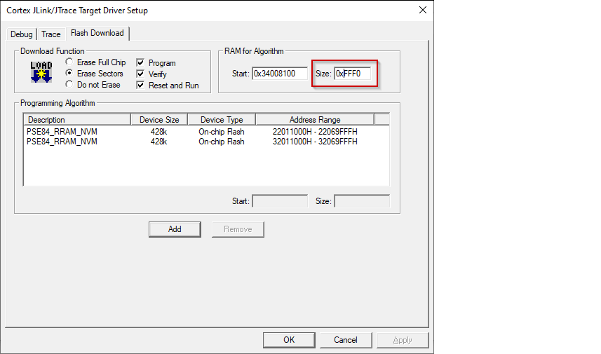
For J-Link, ensure the RAM size for the algorithm is set to 0xFFF0.
-
For either driver, if any application (secure CM33, non-secure CM33, or CM55) should be programmed to external memory, two additional instances of flashloaders with name PSE84_SMIF need to be added using the Add button.
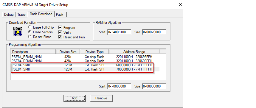
Make sure the second instance handle start address is 0x70000000.
-
Click OK to close the Target Driver Setup dialog.
-
Close the Options dialog.
-
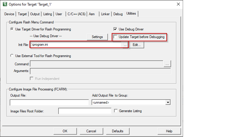
Open the Options dialog again and select the Utilities tab. Deselect the check box Update Target before Debugging and select the program.ini file in the Init File field.
-
Close the Options dialog and save the project.
Non-Secure CM33 project
-
Open the Options dialog. Select the Debug tab and select the applicable debug probe (CMSIS-DAP or J-Link). Make sure that the Load Application at Startup check box is not selected.
-
Select the debug.ini file in the Initialization File field.
-
Click the Settings button to configure the target driver.
-
Select the Debug tab, and choose applicable connection options, the configuration settings are different for CMSIS-DAP and J-Link. Refer to the following sections for the applicable options:
CMSIS-DAP/ULINK2 Target Driver Setup
Use the following options:
-
Port : SW
-
Max Clock : 1 MHz
-
Connect : Normal
-
Reset after Connect : selected
-
Select desired Reset type. For PSOC™ Edge devices, there are two main reset types available: hardware reset using XRES and system reset by SYSRESETREQ. - For SYSRESETREQ the Vector Catch method is applied. The default reset type is SYSRESETREQ.
- For XRES additional follow-up acquisition methods are available, including Test Mode acquisition, Vector Catch, and Break Point acquisition (an alternative acquire).
The method to use is determined by the __Acquisition_Type debug variable. The debug variables are accessible for editing at tab Pack clicking Edit button.
By default, the Test Mode acquisition is applied after XRES.
J-Link Target Driver Setup
Use the following options:
-
Port : SW
-
Max Clock : 1 MHz
-
Connect : Normal
-
Reset : Normal
-
Reset after Connect : selected
-
-
For either driver, switch to the Flash Download tab and select Do not Erase Sectors radio button, and deselect Program , Verify , and Reset and Run check boxes.
-
Click OK to close the Target Driver Setup dialog.
-
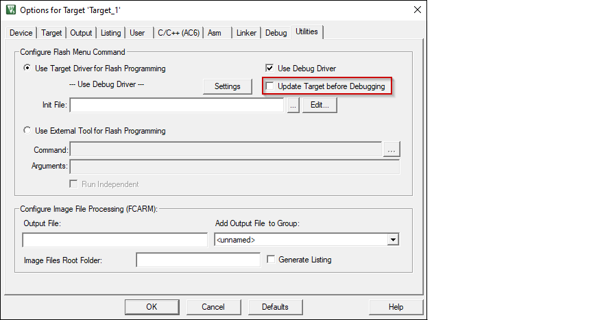
Switch to the Utilities tab. Deselect the check box Update Target before Debugging .
-
Close the Options dialog and save the project.
CM55 project
-
Open the Options dialog. Select the Debug tab and select the applicable debug probe (CMSIS-DAP or J-Link). Make sure that the Load Application at Startup check box is not selected.
-
Select the debug.ini file in the Initialization File field.
-
Click the Settings button to configure the target driver.
-
Select the Debug tab, and choose applicable connection options, the configuration settings are different for CMSIS-DAP and J-Link. Refer to the following sections for the applicable options:
CMSIS-DAP/ULINK2 Target Driver Setup
Use the following options: - Port : SW
-
Max Clock : 1 MHz
-
Connect : Normal
-
Reset : VECTRESET
-
Reset after Connect : Not selected
J-Link Target Driver Setup
Use the following options:
-
Port : SW
-
Max Clock : 1 MHz
-
Connect : Normal
-
Reset : Core
-
Reset after Connect : Not selected
-
-
For either driver, switch to the Flash Download tab and select Do not Erase Sectors radio button, and deselect Program , Verify , and Reset and Run check boxes.
-
Click OK to close the Target Driver Setup dialog.
-
Switch to the Utilities tab. Deselect the check box Update Target before Debugging .
-
Close the Options dialog and save the project.
Secure debug configuration (optional)
The BootROM on the PSOC™ Edge can temporarily disable access to the core's AP. This behavior is determined by the security policy during device provisioning. However, access can be re-enabled using a debug certificate. If a debugger identifies that the AP is disabled, it will upload and verify the certificate found in the "packets/debug_token.bin" file within the current project folder. It's essential to note that neither the name of the certificate file nor its location cannot be changed.
Recommended Values for __Reset_Finish_Delay
Proper device operation may require adjusting the __Reset_Finish_Delay parameter, depending on the device's configuration. The following show the recommended values for this parameter when using KitProg3/MiniProg4 or ULINK2 debuggers/programmers.
- KitProg3/MiniProg4 – 20 000 - 100 000
- ULINK2 – 10 000 - 100 000
For example:
Target programming
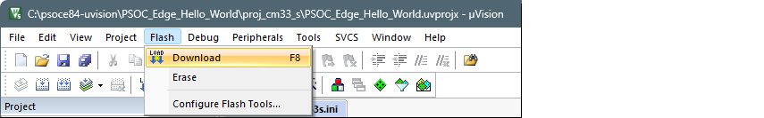
After preparing the combined image and setting up the debugger connection, the next step is to program the target. To accomplish this, follow these steps:
-
Select the µVision instance designated for the secure CM33 application.
-
On the main menu, select Flash > Download .
Launch multi-core debug session
Since two instances of µVision cannot debug the same core simultaneously, it is not possible to debug a secure CM33 application and a non-secure CM33 application at the same time. The following multi-core debug combinations are possible:
- Debugging a secure CM33 project alongside a CM55 project.
- Debugging a non-secure CM33 project alongside a CM55 project.
To initiate a multi-core debug session, you must open one project for the CM33 core (secure or non-scure) and another for the CM55 core in separate instances of the IDE. Here are the steps:
-
Select the µVision IDE instance with the project for the CM33 core and start debugging by selecting Debug > Start/Stop Debug Session .
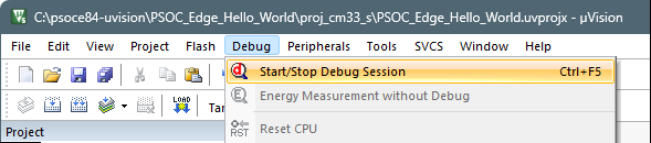
This will reset the target and halt execution at the beginning of the
main()function of the CM33 project. -
Select the µVision IDE instance with the project for the CM55 core and repeat the debugging process.
This will attach to the running CM55 core, which will be in boot mode until the CM33 project starts executing.
Note: Ensure all projects are built and programmed before launching a debug session.
The projects will be similar to these images:
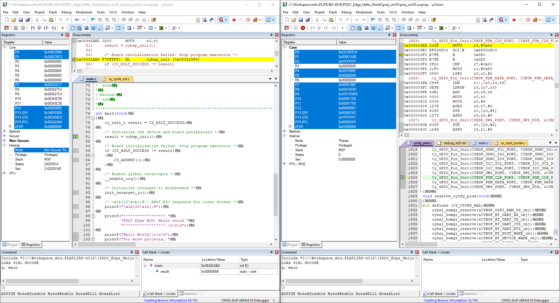
The left side of the screen shows a µVision IDE instance attached to the CM33 core. The right side shows the CM55 core has not started yet. Once the Cy_SysEnableCM55() function on the CM33 core has been executed, the CM55 will start executing its application. You can step through the code by switching back and forth between the two µVision IDE instances.