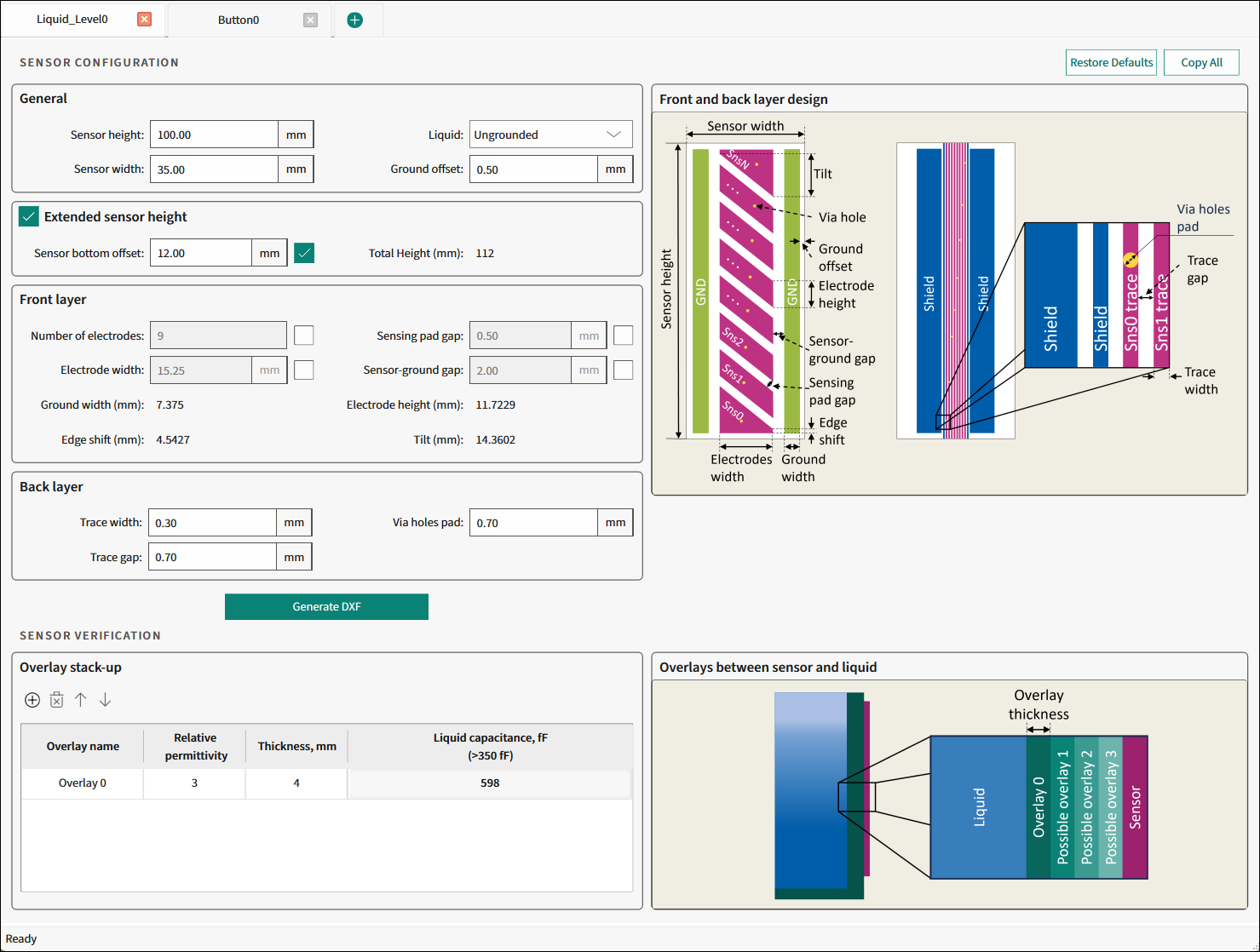
Liquid Level tab
The Liquid Level tab is used to design a liquid level sensor for the preferred application requirements and generate a *.dxf file.
Commands
-
Restore Defaults - Restores parameters values on the current tab to their default values.
-
Copy All - Click this button to copy the list of input and output parameters to the system clipboard as plain text.
Sensor configuration
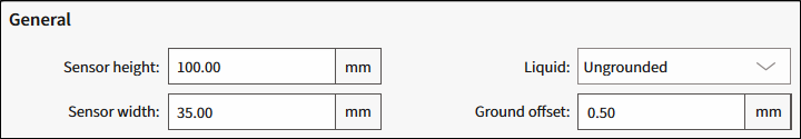
General
-
Sensor height (mm) - The height of the sensor measurable stack-up The range – 30.00-422.5, default – 100.00.
-
Sensor width (mm) - The width of the entire sensor stack-up. The range – 20.00-60.00, default – 35.00.
-
Liquid - Select whether the liquid is Ungrounded or Grounded. Default – Ungrounded.
-
Ground offset (mm) - The spacing gap between the outer ground traces and the edge of the sensor area. The range – 0.5-15, default – 0.50.
Extended sensor height

-
Sensor bottom offset - The height of the sensor offset stack-up. The range – 0-99.99.
-
Total height - The height of the entire sensor stack-up.
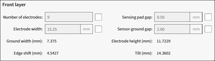
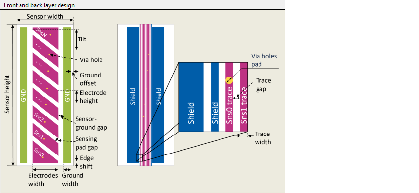
Front layer
Select the relevant check box to use the parameter as an input parameter.
-
Number of electrodes - The total number of electrodes. The range – 3-32.
-
Electrode width (mm) - The horizontal width of each electrode. The range – 1-59.99.
-
Ground width (mm) - Read-only. The width of the ground traces.
-
Sensing pad gap (mm) - The space between the electrodes. The range – 0.1-10.
-
Sensor-ground gap (mm) - The horizontal space between the electrodes and neighboring ground traces. The range – 0.1-10.
-
Electrode height (mm) - Read-only. The height of an electrode when measured at a single point on the horizontal axis.
-
Edge shift (mm) - Read-only. The edge shift area on the top and bottom electrodes. This value can be negative.
-
Tilt (mm) - Read-only. The distance between the highest and lowest points of the tilted edge of an electrode.
Back layer

-
Trace width (mm) - The width of the trace, which connects some segment of the Liquid Level sensor with the connector. The range – 0.1-10, default – 0.30.
-
Trace gap (mm) - The distance between adjacent trace widths. The range – 0.1-10, default – 0.70.
-
Via holes pad (mm) - The diameter of through-hole pads for each sensor between the front and back layer. The range – 0.1-10, default – 0.70.
Generate DXF
Click this button to generate a *.dxf file of the calculated liquid level sensor to a specified file location.
![]()
Illustration of front and back layer design parameters
The illustrative image of the front and back layer design.
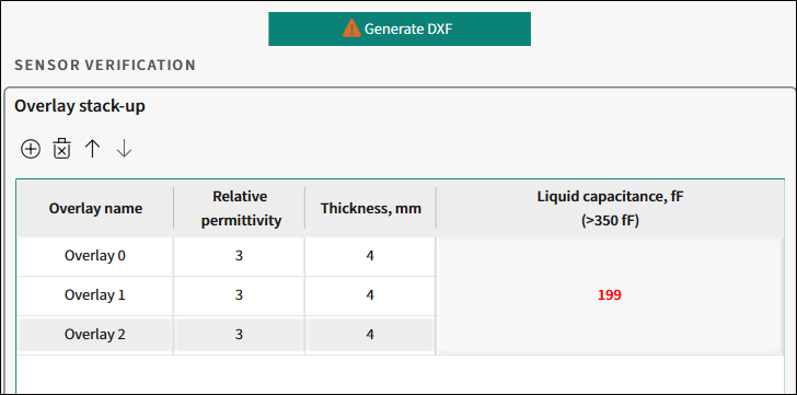
Sensor verification
Overlay stack-up
Toolbar
- To add an overlay, click the "plus" icon.
- To remove an overlay, click the "cross" icon.
- To move an overlay up/down, use the arrows.
Verification parameters table
-
Overlay name - The name of an overlay stack-up.
-
Relative permittivity - Relative permittivity of the overlayer/stack-up material.
-
Thickness, mm - The thickness of an overlay stack-up.
-
Liquid capacitance, fF (>350fF) - The guarding value of calculated sensor capacitance depending on the sensor design and amount of added liquid. In short, the sensor capacitance caused by added liquid. This parameter must exceed 350fF. The sign in the executive button and a message in the Notice List will be displayed to indicated inefficient design.
When the value is below 350fF, you can still generate a *.dxf file but the sensor may have low performance.
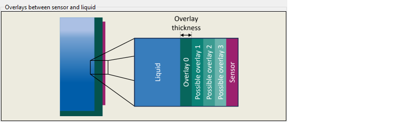
Overlays between sensor and liquid
The illustrative image of the Overlays between sensor and liquid.