AN2010-08 HybridPACK 1: General information and mounting instruction
About this document
Scope and purpose
This application note provides mounting instructions for HybridPACK™ 1 module with recommendations how to screw the module, assemble the PCB, and mount the module onto the heatsink.
Intended audience
Engineers and operators involved in developing a system using the HybridPACK™ 1 module.
Introduction
As a result of the operation of high-power modules, power losses must be dissipated through a heatsink in such a way that the maximum permissible temperature specified in the datasheet cannot be exceeded. The mounting process of power modules is therefore vital because it affects the module’s thermal performance and its reliability, which is critical for automotive applications.
Ensure that the ground straps should be worn while working with the components and that the ESD safety instructions must be followed at all times, since IGBT modules are electronic-static sensitive components. In addition, the maximum permissible values set out in the product datasheet and application notes are absolute limits which, in general, cannot be exceeded for a short period of time, as this may lead to the destruction of the component. In addition, this application note does not cover all types of applications or conditions. As a result, the application note cannot replace a detailed assessment and examination of the suitability of the targeted applications carried out by you or your technical divisions. In any event, the application note must not become part of any supplier-agreed warranty, unless the supply agreement determines otherwise in writing.
Proposal for designing a driver board
On the basis of the HybridPACK™ 1 dimensions, a proposal for designing a driver board can be presented (see Figure 1). The diameter of the end-hole of the module solder pin connection should be
mm.
Figure 1. Proposal for designing a driver board for HybridPACK™ 1 module

Mounting a driver board onto the module
The driver board can be mounted directly on top of the module by solder. If a driver board or module adapter board (PCB) is soldered directly on top of a module, the contact joints (solder connections) between the PCB and the auxiliary contacts of the module must be mechanically relieved as much as possible. The contact points are relieved by mounting the PCB directly onto the module at the four mounting stand-offs (Figure 2) using self-tapping (thread-forming) screws or a similar assembly material. The length of the used self-tapping screws depends on the PCB thickness. Example: For mounting a PCB with 1.6 mm thickness, a self-trapping screw with 2.5 mm diameter and 8 mm length, such as Delta PT 25×8 WN 5451 from EJOT, should be used.
Figure 2. PCB mounting stand-off of HybridPACK™ 1 module
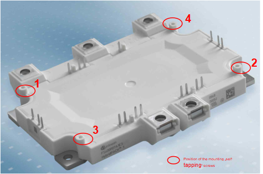
The screws should be mounted in the sequence shown in Figure 2. The initial 1.5 mm of the mounting stand-off serves only as guidance and cannot be used with any force. The thread in the plastic will form when the screws are driven. In addition to manually inserting the screws into the mounting stand-offs, an electronically controlled or at least slowly turning electric screwdriver (≤300 rpm) is preferred (due to the lack of accuracy, pneumatic screwdriver is not recommended). The maximum applied Torque Mmax is 0.4 Nm ±10%. The effective length of the screw thread entering the mounting stand-off should be of a minimum length of lmin ≥ 6 mm and a maximum length of lmax ≤ 8 mm, taking into account the thickness and weight of the driver PCB.
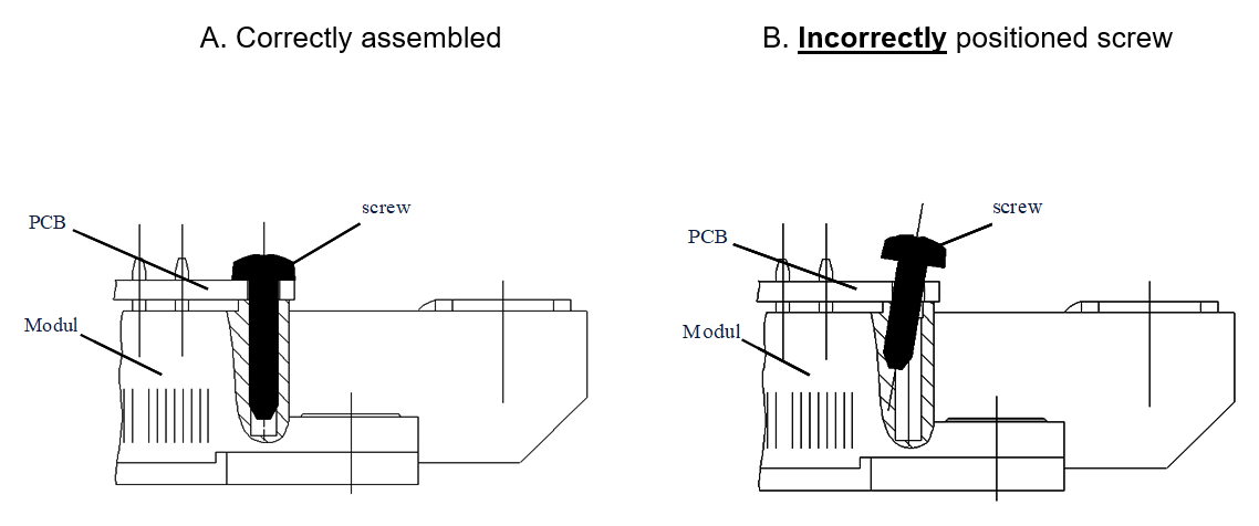
To avoid damage or breakage of the stand-off, a screw must be inserted straight into the stand-off during assembly (Figure 3).
Figure 3. (A) Correctly assembled screw into the mounting stand-off and (B) incorrectly positioned screw into the mounting stand-off
The recommended screws and torques are based on laboratory tests. Depending on the screws and tools used, it may be necessary to adapt the assembly process accordingly.
The solder process (manual soldering, selective soldering, or wave soldering) may begin after the PCB is mounted. The mechanical strain on the solder points can be minimized when adhering to this sequence of assembly.
During the entire soldering process, care should be taken not to overheat the plastic case and hence deform it, if the soldering temperature is too high or the process time is too long at the auxiliary pin.
According to IEC68 Section 2, a maximum solder temperature of T = 260°C for a maximum process time of tmax ≤ 10 s must be observed during the solder process.
Condition of the heatsink for module assembly
In order to avoid exceeding the maximum permissible temperature specified in the datasheet during switching (Tvj_op = 150°C) in operation, the power loss occurring in the module must be dissipated. Therefore, designing a cooling system/heatsink is of great importance to achieve good performance.
The condition of the heatsink surface in the area where the module is mounted is very important, since the interface between the heatsink and module has a decisive influence on the heat transfer of the entire system.
The contact surfaces, the baseplate of the module, and the surface of the heatsink must be free of contaminants and cleaned with a fresh, lint-free cloth.
The contact surface of the heatsink should not exceed the following values for a length of L = 100 mm:
Surface flatness ≤ 50 µm
Surface roughness Rz ≤ 10 µm
The heatsink must be sufficiently stiff for assembly and subsequent transport in order not to exert any additional strain or pulling forces on the baseplate of the module. During the entire assembly process, the heatsink must be handled without twist.
Application of the thermal compound
Due to the different surface shapes of the module baseplate and heatsink, they do not touch each other across the entire area, so that a certain punctiform separation between the two components cannot be avoided.
In order to dissipate the losses occurring in the module and to achieve a good heat flow into the heatsink, all local cavities must be filled with thermal compounds. When using a heat conductive paste, homogeneity must be ensured.
A well-adhered layer will fill all cavities without preventing the metallic contact between the baseplate and the heatsink. In order to ensure a continuously favorable heat transfer resistance, a compound should be selected that shows permanent elastic features. The paste should be applied in such a way that there is no contamination of the screw holes so that the bolt torques are not degraded.
Common rollers or fine-toothed spatulas may be used to apply the thermal compound. On the baseplate of the module, the layer thickness of the grease should normally be 50 µm to 100 µm.
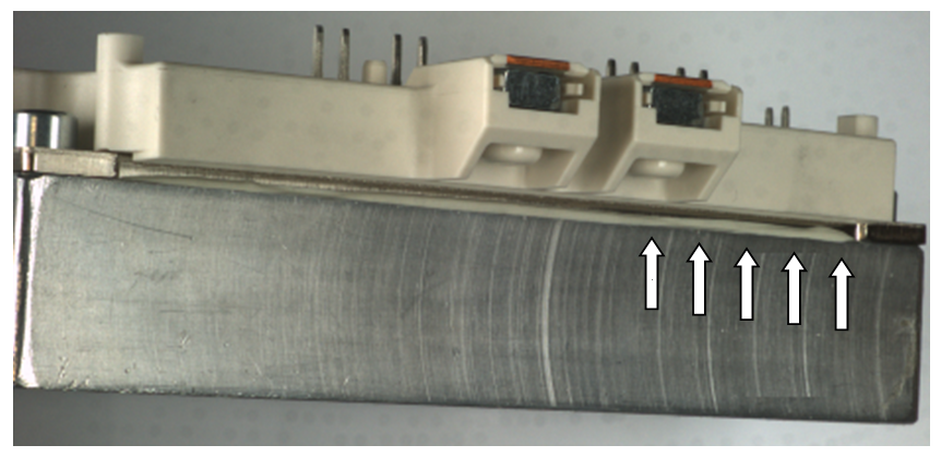
Manual application of a heat conductive paste with a constant layer thickness in the µm-region is, of course, problematic. The homogeneity and reproducibility of the layer thicknesses is always questionable. In general, the application is sufficient if, after tightening the module, a small amount of surplus paste is squeezed around the sides of the module (see Figure 4)
The imprint of disassembled modules should be checked during the training phase for the qualification and verification of the assembly process.
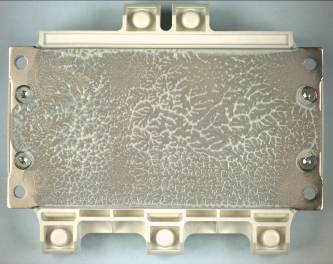
For this purpose, the thermal compound must be applied according to the mounting notes. After heating, unbolting, and carefully lifting off the module, a branch-like structure can be seen on the baseplate as shown in Figure 5. In addition, the layer thickness of the thermal compound after application can be checked using a wet film comb.
For a homogenous layer thickness of 100 µm, a volume of V = 0.73 cm3 was obtained from a HybridPACK™ 1 module with a baseplate size of 57 mm × 128 mm. These volumes can be measured using a syringe or the tube.
Figure 4. Mounted HybridPACK™ 1 module with thermal compound squeezed out at the side of the module
The application of a thermal compound by a screen print process is recommended. In addition to an optimized and module-specific distribution of the heat conductive paste, this procedure can achieve a homogeneous and reproducible layer thickness application.
Figure 5. Print image of HybridPACK™ 1 disassembled with a branch-like thermal compound structure
Screen print template
Contrary to conventional methods of paste application, this procedure applies the thermal compound only to areas where it is required.
A surface scan of the baseplate was used to determine the quantity of thermal compound required. HybridPACK™ 1 was scanned twice along the baseplate for this purpose. Two profiles were obtained from this scanning: “Profile Line1” (blue line) and “Profile Line2” (black line).
Figure 6 shows the baseplate profile of a mounted HybridPACK™ 1 module (FS400R07A1E3).
Figure 6. Baseplate profile of a mounted HybridPACK™ 1 module (FS400R07A1E3)
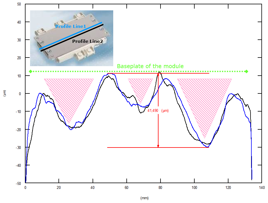
The unevenness of this baseplate is usually around 40 μm. The green line indicates the location of the baseplate. The start and end points of the baseplate are represented by the end points of green line. The pink areas below the baseplate of the module indicate the areas where HybridPACK™ 1 has no direct thermal contact with the heatsink.
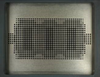
These cavities must be filled with thermal compounds. The surface scan is divided into a grid to determine the required paste. For each raster point, a sufficient amount of paste must be determined. Figure 7 shows the screen print template result of this procedure.
Figure 7. Screen print template for an HybridPACK™ 1 module
The corresponding drawing for the module type is available. A CAD drawing of this screen can be ordered from your sales partner.
For further notes regarding the application of screen print templates for the application of thermal grease, refer to the application note "AN2006-02: Application of screen + print templates.pdf".
Screw to mount the module to the heatsink
The following screws are recommended for mounting the module: DIN M5 screws that comply at least with class 6.8 (for example, according to DIN 912 (ISO4762), ISO 7380, DIN 6912, and DIN 7984) in combination with a suitable dented edge washer and spring washer (for example, according to DIN 433 or DIN 125) or the combination of both the “dented edge washer.”
The clearance and creepage distances specified in the HybridPACK™ 1 datasheets are the shortest clearance and creepage distances for unassembled and unconnected modules.
When selecting suitable M5 screws, washers, and spring washers for mounting the module, it is recommended to consider the resulting clearance and creepage distances between the power terminal and the nearest bolt head or washer during the development phase.
Mounting the module to the heatsink
The clamping force of the module resulting from the assembly process to the heatsink depends on the torque applied and the heatsink material. The following torque values specified in the datasheet result from steel screws in aluminium heatsinks with a dry M5 thread and their typical friction factors of µG = 0.2~0.25 (µG = friction coefficient thread in heatsink):
In order to ensure good thermal contact with the heatsink, it is recommended to tighten the four M5 fastening screws using a washer (according to DIN 433) and a spring washer (according to DIN 127).
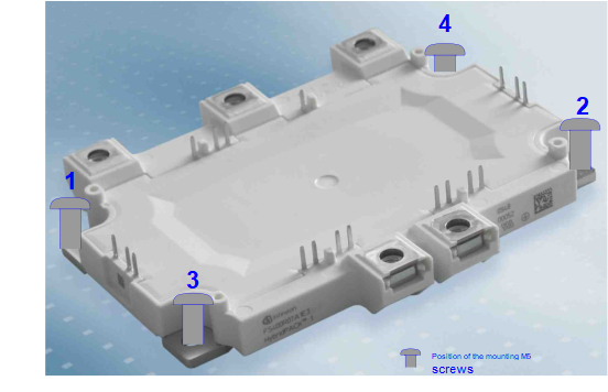
Place the module with the thermal compound applied onto the heatsink and fix it with two screws
Fix the screws with 0.5 Nm (hand tight crosswise) in the sequence shown in Figure 8
Tighten the screws with 3–6 Nm in the same sequence (crosswise)
Figure 8. Tightening sequence to mount the module
When using a thermal compound, it may be necessary, depending on the type of paste used, to check that the tightening torques of the fastening screws correspond to the correct value after a heat-up test. If thermal foils are used instead of heat-conductive paste, it is recommended to carry out this additional check. The given torques and application notes are valid when using the thermal compound. It is absolutely necessary to perform own tests and measurements with the heat-conductive foils envisaged!
When selecting the heat-conductive paste or heat-conductive foil, consideration should be given to thermal contact and long-term stability with the manufacturer.
Connecting the bus bars to the power terminals
In order to keep the switching overvoltage as low as possible by minimizing stray inductance, the DC power side should be connected with a laminated DC bus bar. In accordance with the RBSOA data in the datasheet, compliance with the maximum permissible voltage at the power terminals and at the IGBT chip can be guaranteed.
For the connection of power terminals, DIN M6 screws which comply at least with class 6.8 are required in combination with a suitable washer and spring washer or a complete combination screw. These should be tightened with a recommended torque of Mmin = 3.0 Nm to Mmax = 6.0 Nm.
When selecting the bolt length, the layer thickness of the connecting parts must be subtracted from the total length of the screws. The effective length of engagement into the module thread may not exceed the maximum specified depth of 10 mm.
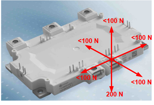
As shown in Figure 9, the connected parts must be mounted to the power terminals in such a way that the specified static forces are not exceeded during assembly or later in operation.
Figure 9. Maximum permissible static pull-and-push forces at the power terminal of HybridPACK™ 1
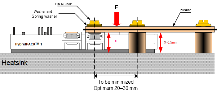
Connecting the power terminals with ideal strain relief
To connect the power terminals with the best possible strain relief, a recommended assembly schematic is shown in Figure 10, in which a bus bar is connected to the power terminals in such a way that only a low force is applied to them, even during shock or vibration conditions. The power terminals are able to withstand the force F best in the direction from the terminal to the baseplate. Force in other directions has to be avoided. This must also be taken into account in the tolerance of the bus bar.
Figure 10. Concept drawing of HybridPACK™ 1 assembly with ideal strain relief
Storage and transport
The module can be stored at the temperature limits specified in the datasheet, but it is not recommended.
According to IEC60721-3-1, class 1K2, the recommended storage conditions should be ensured for a maximum storage time of 2 years.
Maximum air temperature: Tmaxair = +40°C
Minimum air temperature: Tminair = +5°C
Maximum relative humidity: 85%
Minimum relative humidity: 5%
Condensation: not permissible
Precipitation: not permissible
Icing: not permissible
The HybridPACK™ 1 modules do not require pre-drying of the case prior to the solder process, which is recommended for moulded discrete components (for example, microcontrollers, TO-cases, etc.).
Data matrix (DMX) part marking
Infineon Technologies, as a part of the electronic industry, has made a significant contribution by using a data matrix part marking to transform the way HybridPACK™ products are traced, both in the manufacturing process and throughout the life cycle of the product or component. Total traceability means significant improvements in process and quality control.
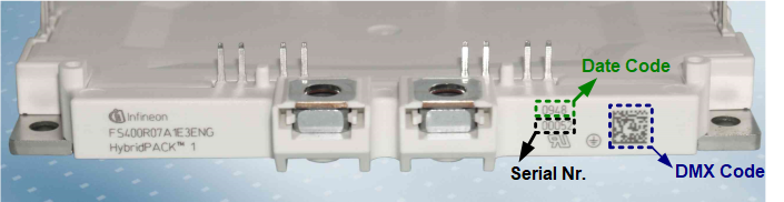
Data matrix is a two-dimensional code that is machine readable with a conventional 2D reader or scanner. Readers are able to read low-contrast marks, damaged codes, and even codes on highly damaged surfaces. A side view of HybridPACK™ 1 is depicted in Figure 11. The marking of the module, together with the data matrix (DMX)-Code, Date Code, and Serial Nr, can be seen in this figure.
Figure 11. HybridPACK™ 1 figure (side view)
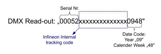
When the DMX-Code of the module depicted in Figure 11 has been read out with a conventional scanner, the following characters will be displayed:
Figure 12. HybridPACK™ 1 DMX Read-out
Screen print template for the HybridPACK 1 baseplate
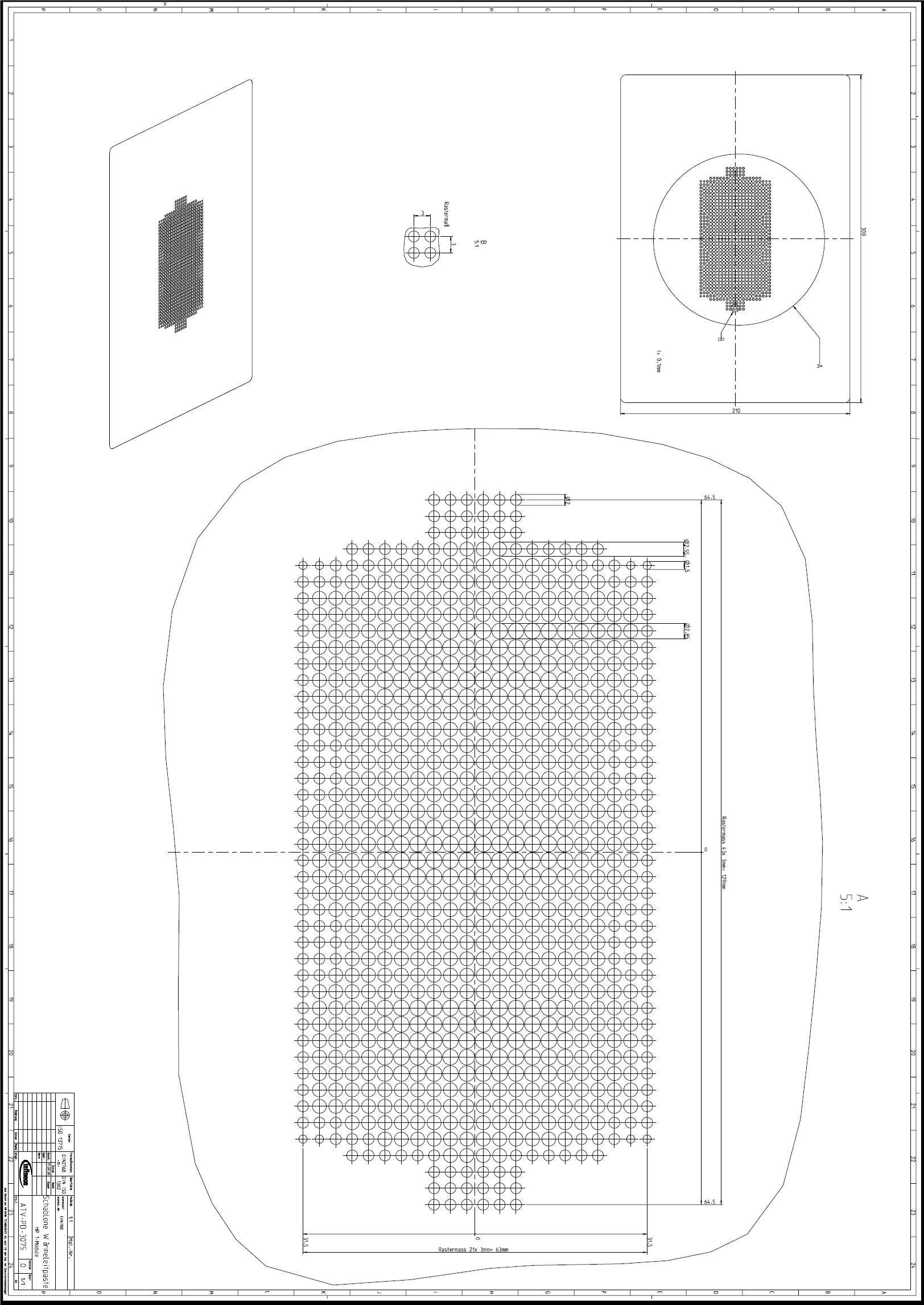
In Figure 13, a screen print template for the HybridPACK™ 1 baseplate can be found. Use the recommended screen print template for applying the thermal compound.
Figure 13. Screen print template for the HybridPACK™ 1 baseplate
Revision history
| Document version | Date of release | Description of changes |
|---|---|---|
| 1.0 |
| |
| 1.1 | 2010-08-10 | |
| 1.2 | 2023-12-07 |
|