AN239646 PMSM FOC using PSOC™ Control C3 MCU
About this document
Scope and purpose
This document describes the implementation of permanent magnet synchronous motor (PMSM) sensorless field-oriented control (FOC) using the Infineon's
PSOC™ Control C3
.
Intended audience
This document is intended for customers who would like a configurable system for FOC control with sensorless feedback using the
PSOC™ Control C3
.
Introduction
Sensorless FOC for brushless permanent magnet synchronous motors has been widely used as a control method in variable frequency drive applications. The system cost and energy efficiency are the two main factors driving the adoption of FOC-driven three-phase motors. For most applications, three shunt resistors located at the low side of inverter switches are used to measure three-phase motor currents for FOC. However, a single shunt is also widely used for cost-sensitive applications.
The
PSOC™ Control C3
is designed for real-time control applications such as motor control. The uses of various peripherals intended for motor control applications are described in this document.
Key features
PSOC™ Control
C3 key features
32 bits, single-core Arm® Cortex®-M33 based MCU running up to 180 MHz clock frequency. It supports DSP, FPU, MPU, and state-of-the-art security features
Supports up to 240 MHz peripheral clock
256 KB read-while-write flash with ECC
64 KB SRAM with ECC support
16 KB instruction cache (I-cache)
Hardware CORDIC to accelerate calculation
12-bit, 12 Msps SAR ADC block, support 16 samplers for simultaneous sampling
Sixteen 16-bit and four 32-bit timer/counter pulse-width modulator (TCPWM)
Two DMA controllers with 16 channels each
Smart I/O capable of logically combine the outputs of multiple channels
Analog comparators with in-built DAC to generate the comparator reference
FOC motor control features
Multiple motor control capabilities
Speed control
Current control
Torque control
Voltage control
Adaptive sensorless observer that provides minimal phase distortion. It can observe rotor angle, speed, stator angle, stator flux magnitude, and load angle
Start-up technique
Open-loop Volt/Hz
Rotor prealignment
Six-pulse injection
High-frequency injection
Maximum torque per amp (MTPA)
Maximum torque per volt (MTPV)
Field weakening
Active damping
Motor I2T protection
Various voltage modulation methods
DSP math library
Hardware and software fault detection for protection
Floating point implementation of all control features
Motor profiler to facilitate tuning when new motors are used
High-sampling-rate oscilloscope support for signal monitoring
Abbreviations and acronyms
API | Application programming interface |
CORDIC | Coordinate rotation digital computer |
DMA | Direct memory access |
DSP | Digital signal processor |
FOC | Field-oriented control |
FPU | Floating point unit |
HPPASS | High-performance programmable analog subsystem |
I-PMSM | Interior permanent magnet synchronous motor |
ISR | Interrupt service routine |
MCU | Microcontroller unit |
MPU | Memory protection unit |
PMSM | Permanent magnet synchronous motor |
PWM | Pulse width modulation |
RFO | Rotor frame orientation |
SFO | Stator frame orientation |
SMPMSM | Surface-mounted permanent magnet synchronous motor |
SVM | Space vector modulation |
TBC | Trapezoidal block commutation |
TCPWM | Timer/counter, and pulse-width modulator |
PSOC™ Control C3 resource allocation
PSOC™ Control C3
peripherals allocated for the FOC sensorless solution are captured in
Table 2
.
PSOC™ Control C3 peripherals | Usage | Default resource allocation |
|---|---|---|
TCPWM | PWM_U: PWM generation for phase U, 16-bit resolution | TCPWM0-G1-C0 |
PWM_V: PWM generation for phase V, 16-bit resolution | TCPWM0-G1-C1 | |
PWM_W: PWM generation for phase W, 16-bit resolution | TCPWM0-G1-C2 | |
TCPWM | ADC0_ISR0:
| TCPWM0-G1-C3 |
TCPWM | SYNC_ISR1:
| TCPWM0-G0-C0 |
TCPWM | PWM_START: Start all the timer in sync. | TCPWM0-G1-C4 |
ADC | ADC_SAMP_IU: Phase U current sensing | AN_A0 |
ADC_SAMP_IV: Phase V current sensing | AN_A1 | |
ADC_SAMP_IW: Phase W current sensing | AN_A2 | |
ADC_SAMP_VBUS: DC link voltage sensing | AN_A4 | |
ADC_SAMP_VPOT: Potentiometer for onboard speed control | AN_B4 | |
ADC_SAMP_TEMP: Power board temperature sensing | AN_B6 | |
Interrupt controller (NVIC) | ISR1: Timer interrupt | tcpwm_0_interrupts_0_IRQn |
ISR0: ADC conversion complete interrupt | pass_interrupt_sar_entry_done_0_IRQn | |
MATH | FPU | – |
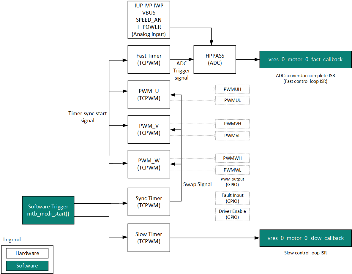
PSOC™ Control C3 peripheral interconnectivity
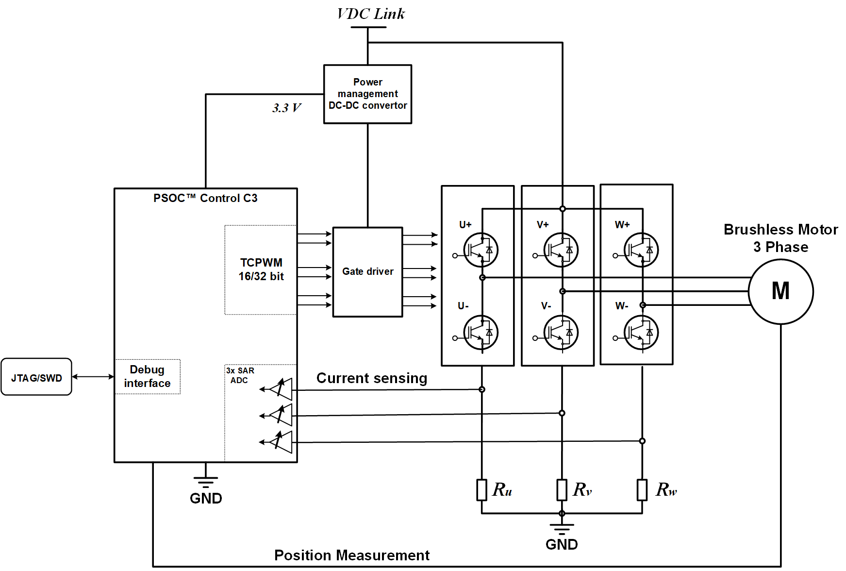
The following figure shows the inter- connection between
PSOC™ Control C3
peripherals using solution personality used for three-shunt sensorless FOC.
Figure 1.
Peripheral inter-connectivity
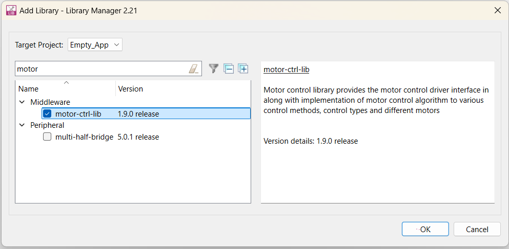
Motor control library
The motor control library is a ModusToolbox™ middleware asset. It can be integrated with a new application using Library Manager as shown in
Figure 2
.
Figure 2.
Motor control library
It has a well-defined layered architecture including the hardware interface layer as shown in
Figure 3
.
Figure 3.
Motor library folder structure
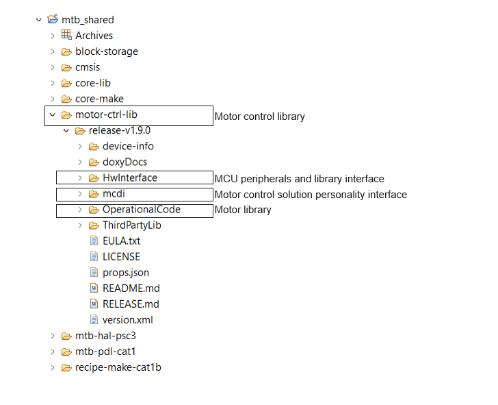
Hardware interface layer provide the interface functions to integrate the device agnostic library to the hardware modules.
PMSM sensorless FOC basics
This section introduces the different types of PMSM motors and the structure of a typical sensorless FOC system.
Types of synchronous motors
There are two types of PMSMs, the salient and the non-salient type of motor. They differ in how magnets are placed in the rotor.
Figure 4
shows the non-salient surface mounted permanent magnet synchronous motor (PMSM/SMPMSM) [left] and a salient interior permanent magnet synchronous motor (IPMSM) [right].
Figure 4.
Structure for SMPMSM and IPMSM
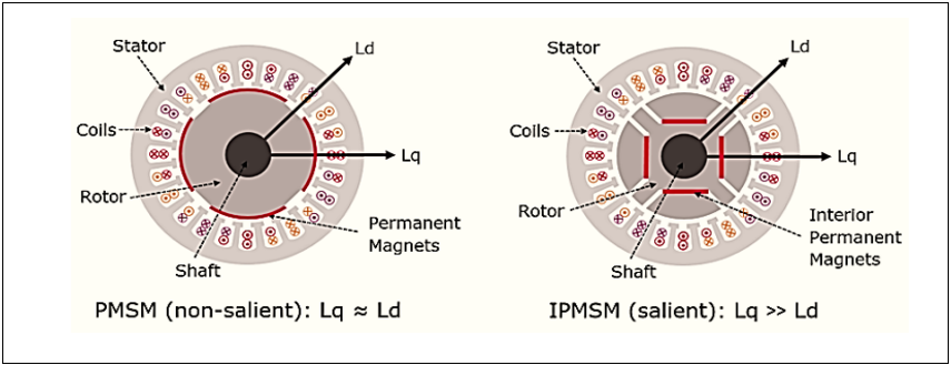
IPMSM has distributed windings with interior permanent magnets inside the rotor causing a saliency and therefore, also reluctance torque. In SMPMSM, magnets are placed on the surface of the rotor, it has no saliency. In the non-salient type of synchronous motor, the stator inductance is not dependent on the rotor position whereas in the salient type of motor the stator inductance is dependent on the rotor position.
Synchronous motors can provide torque when a rotating electromagnetic field and a constant field are standing still relative to each other. To develop a constant torque, the stator field must rotate synchronously with the rotor (permanent magnets) which is excited by a DC power supply.
The d-axis refers to the direct axis (main flux path axis that is normally in the orientation of the permanent magnets) of a synchronous machine, while the q-axis refers to the quadrature axis.
Sensorless FOC system overview
FOC is also known as vector control, it provides better efficiency at higher speeds than sinusoidal control. Vector control guarantees optimized efficiency even during transient operation by perfectly maintaining the stator and rotor fluxes. It gives better performance on dynamic load changes when compared to all other control techniques.
Figure 5
shows the hardware block diagram of a typical sensor less FOC system. It consists of MCU, inverter, motor, current sensing circuit, and communication interfaces. These components can be on the same controller board or separated in the system such as on an MCU board and an inverter board.
Figure 5.
Overview of a typical FOC system
Inverter
The objective of any motor control method is to generate a reference voltage to be applied to the motor windings using an inverter. Since the inverter is made of discrete switching devices, it cannot produce a continuous voltage on its output. Therefore, a modulation scheme is needed to create a voltage that has an average equal to the reference voltage.
Figure 6
shows the basics of modulation.
Figure 6.
Voltage modulation
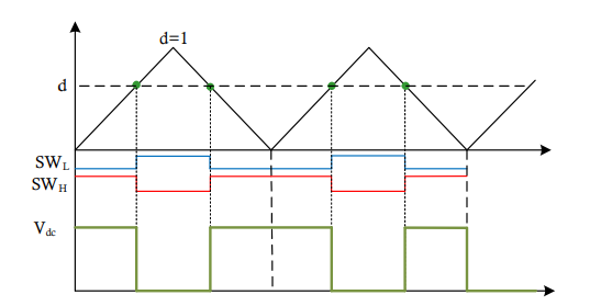
As shown in
Figure 6
, the reference voltage 𝑑 generated by the controller is compared with a triangular waveform which creates the switching signals for low side SWL and high side SWH switches in the associated leg of an inverter. The result would be the voltage waveform with an average of 𝑑 x 𝑉dc in the leg of the inverter (with respect to the negative DC bus).
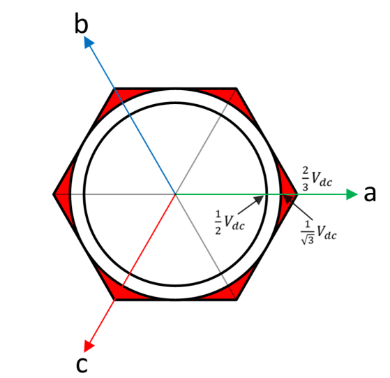
In a three-phase inverter, the maximum voltage vector that can be generated depends on the modulation scheme. As it is shown in the following figure, the maximum voltage that can be generated by the inverter is 2/3 × 𝑉𝑑𝑐 (with respect to the neutral point of the motor). Space Vector Modulation (SVM) and Neutral Point Modulation can both produce 1/√3 × 𝑉𝑑𝑐 . These modulation schemes will be discussed in the following sections.
Figure 7.
Inverter voltage generation
Space vector modulation
In the SVM method, the voltage reference is created using the two adjacent voltage vectors as shown in
Figure 8
.
Figure 8.
SVM voltage creation
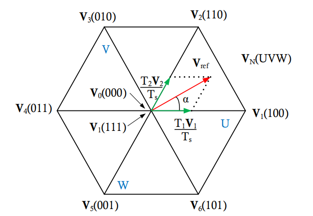
With a switching period of 𝑇𝑠 , the reference voltage is created by applying
and
for
and
respectively and
and
for the rest of the period. Therefore,
and the duration of each voltage vector can be calculated as:
where 𝑚 is the modulation index and defined as:
Figure 8
shows the two different switching schemes for each leg of the inverter based on the timings acquired for each voltage vector. There are a few different switching schemes that can be used to create the vectors determined by the SVM method. However, 7 segment and 5 segment switching methods as shown in the following figure are the most popular (
).
Figure 9.
SVM switching methods
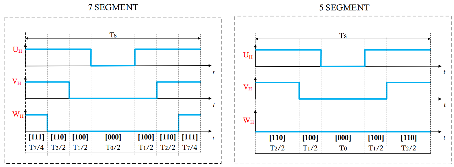
The difference between the two switching methods is that in 7 segment, both
and
times are used to create zero voltage while in 5 segment only
is used to create zero voltage.
Note that the 5 segment switching method creates less switching compared to the 7 segment which reduces the switching losses. However, the current ripple in this switching method is higher compared to 7 segment.
Neutral point modulation
Neutral point modulation is another method to increase the modulation index beyond 1.0, similar to the SVM method. This modulation method can be used to increase the modulation index to 1.15.
Figure 10
shows the type of modulation work.
Figure 10.
Neutral point modulation scheme
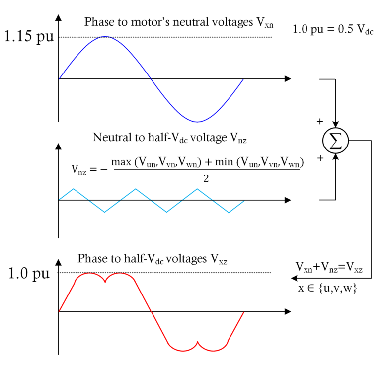
In
Figure 10
, the 𝑉𝑥𝑛 is the phase reference voltage created by the controller. Note that this voltage is phase-to-neutral not phase-to-phase. 𝑉𝑛𝑧 is a common mode voltage that must be added to all the three-phase voltage references. This voltage is calculated as:
The voltages with respect to the half 𝑉𝑑𝑐 point of the inverter are denoted as 𝑉𝑥𝑧 as shown in
Figure 10
.
As mentioned, this is a simple modulation strategy to increase the effective modulation index which creates results that are identical to those of SVM while being less computationally demanding. The switching can also be scheduled like the SVM method according to the SVM switching methods image.
Current sensing in sensorless FOC
FOC needs phase currents as input to control the motor. In sensorless FOC, phase currents are needed to estimate the rotor position in addition to field-oriented control. Therefore, fast and accurate current sensing is the core of PMSM sensorless FOC. It enhances the system performance by reducing the torque ripple or noise. The delay in current sensing path or inaccurate current sensing leads to a distorted current waveform and it produces torque ripple, which results in inefficient performance.
The three-phase or two-phase current sampling must be done when the low-side switches are ON, and the current sampling point must be synchronized with the pulse-width modulation (PWM). Different current sampling techniques and associated challenges are described in the following sections.
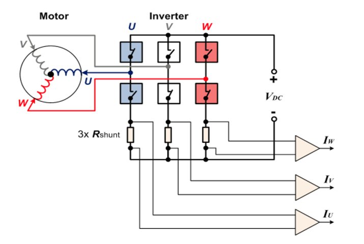
Three-shunt current sensing
This technique uses low-side current sensing in which shunt resistors located at the base of the inverter bridge to measure the currents that are flowing through the phases as shown in the
Figure 11
.
Figure 11.
Three-shunt current measurement
In three-shunt current sensing, the ADC conversion trigger is set at half of the PWM cycle where all the low side switches are on, and the high side switch is off. In each SVM sector, the all three-phase currents are assigned to be measured at the same time as shown in
Figure 12
.
Figure 12.
Three-shunt current sampling with respect to SVM sectors
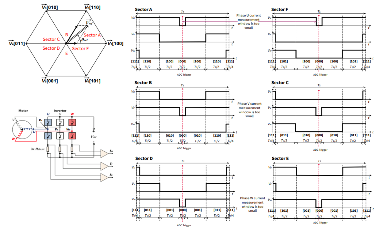
In the case of over modulation, phase current is immeasurable in certain regions due to insufficient current measurement time that results in inaccurate sampling of current. The immeasurable area is shown in the following figure.
Figure 13.
Immeasurable areas
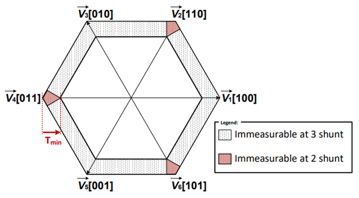
For example, in SVM sector A and F shown in
Figure 12
, the two most critical phase currents are 𝐼𝑉 and 𝐼𝑊 as the phase U current can be inaccurate. This is because with a high modulation index, the window to measure phase U current can be short and the reading of the phase U current could be inaccurate.
Sensorless FOC implementation with PSOC™ Control C3
This chapter describes the implementation of a sensorless FOC using the Infineon's
PSOC™ Control C3
.
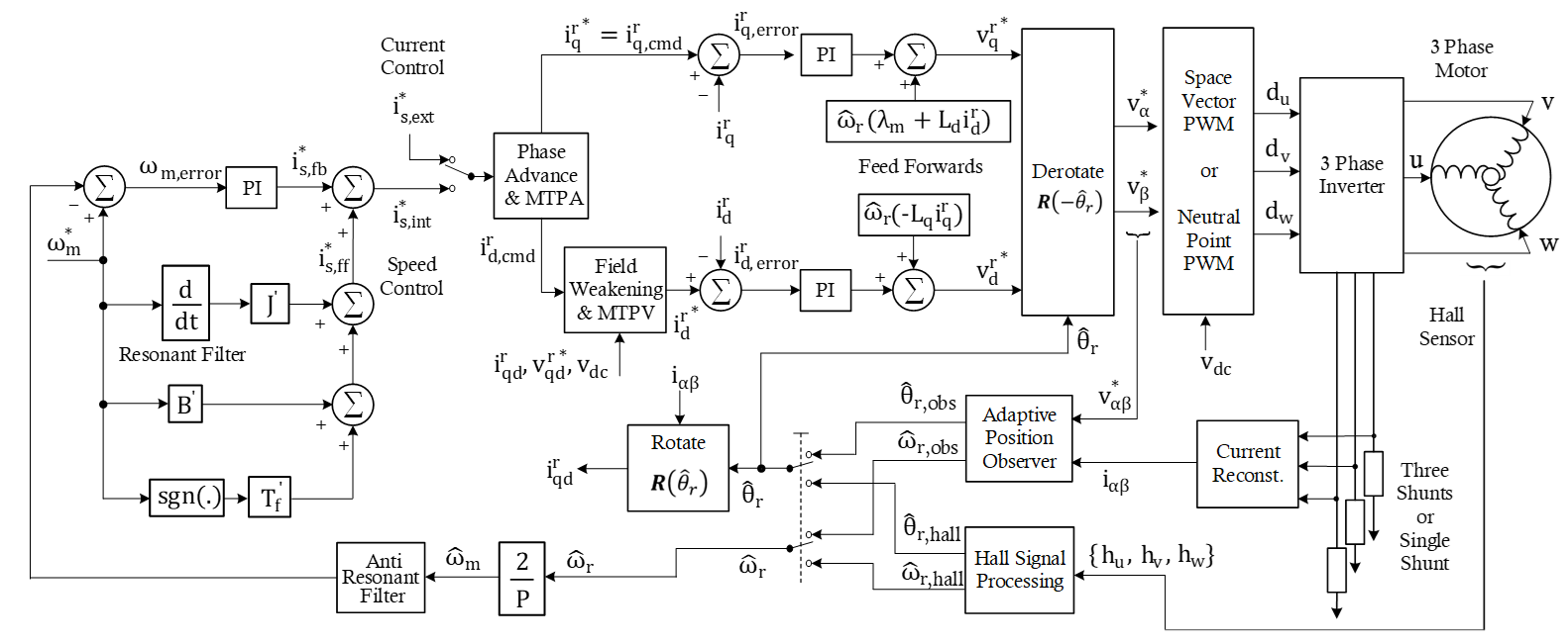
Sensorless FOC block diagram
Figure 14
shows a block diagram of the sensorless FOC algorithm implemented using the
PSOC™ Control C3
. It shows the major software components and their connections.
Figure 14.
Sensorless FOC block diagram
PSOC™ Control C3 features for FOC
Multiple TCPWM units, high-performance programmable analog subsystem (HPPASS), flexible signal connectivity across different peripherals, idle ADC channel sampling, and the CPU performance makes the
PSOC™ Control C3
an ideal device for PMSM FOC applications.
Figure 15.
PSOC™ Control C3
functional block diagram
The following sections explain the usage of the key hardware modules of
PSOC™ Control C3
for sensorless FOC applications.
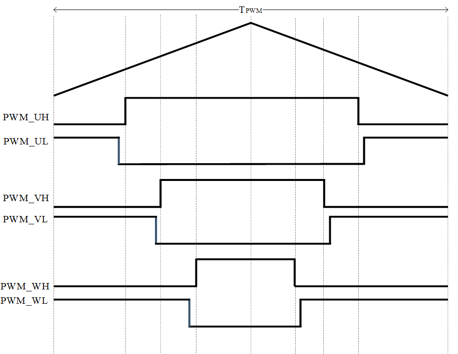
PWMs
The space vector modulation (SVM) transforms the stator voltage vectors into PWM signals (compare match values). The TCPWM timer unit of
PSOC™ Control C3
has been designed to generate the PWM signals. Three channels of TCPWM Group-1 are used to generate six PWM signals for the SVM as shown in
Figure 16
. The PWM period (TPWM) is setup according to the PWM frequency, whereas the three compare values define the ON-time for the three phases. TCPWM Group-1 channel 4 (ADC trigger timer) is used in sync with the PWM timer to generate the trigger events for the ADC conversion. A compare event is used for triggering the current sampling. Sampling starts automatically on the defined compare match event.
Figure 16.
PWM signals with dead-times (center-aligned mode)
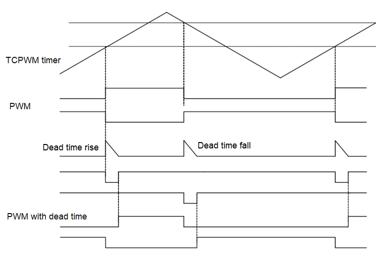
Dead-time configuration
To guarantee the safety of the inverter bridge, the TCPWM unit contains a programmable dead-time generation block. Dead-time insertion prevents the short circuits of switches. It adds a delay between the switch-off time of MOSFET and the switch-on time of its complementary MOSFET to avoid the short circuit shown in
Figure 17
.
Figure 17.
PWM with dead-time
Synchronization of timer counters
All PWM and ADC trigger timers need to start simultaneously in the FOC algorithm. In
PSOC™ Control C3
it can be achieved using a hardware trigger or synchronized software-based event generation.
In FOC code example, one timer instance "PWM_START" is configured in single shot mode and the overflow event signal is used as a trigger pulse to start all PWM and ADC trigger timers. Application uses the software API to start the "PWM_START" timer.
Current sensing
The ADC block of the HPPASS module is used to convert the current measurement from the shunt resistance to a digital value that can be used in the software. A simplified block diagram of HPPASS is shown in
Figure 18
.
Figure 18.
HPPASS overview
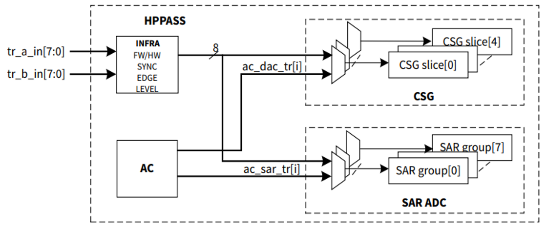
The PMSM FOC sensorless solution configures the ADC channels of the HPPASS module for current measurement, DC bus voltage measurement, analog speed measurement, and power board temperature measurement.
The
PSOC™ Control C3
provides an extremely fast ADC with a direct trigger from the PWM unit to the ADC. This optimizes the system performance and CPU load significantly, resulting in improved current sampling performance. The current sampling point in sync with PWM is described in the following sections.
Three-shunt current measurement
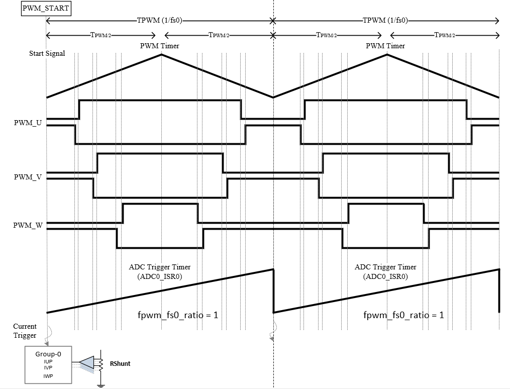
In
PSOC™ Control C3
, the capture compare 0 event of the ADC trigger (ADC0_ISR0) timer is used for current triggering. The ADC trigger timer is running in sync with the PWM timer. The measurement of ADC is set at half of the PWM in each PWM cycle where all the low-side switches are ON as shown in
Figure 19
.
Figure 19.
Three shunt current measurement
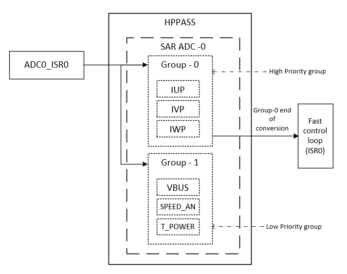
All direct ADC channels exhibits the property of idle sampling (zero sample time from the trigger instance). This solution uses 6 ADC channels, divided into two groups as shown in
Figure 20
.
High-priority group:
Contains all current channels (direct channels)
Low-priority group:
Contains the bus voltage (direct channel), speed, and temperature sense channels
On a trigger event, all channels transition to the HOLD state simultaneously. The channels associated with the high-priority group are converted first, followed by the low-priority group channels. Conversion complete of a high-priority group is connected to an interrupt service routine, called the fast control loop. Fast control loop ISR reads the conversion result and execute the control loop.
Figure 20.
HPPASS configuration for three shunt FOC
ADC post-processing
The
PSOC™ Control C3
SAR ADC has various post-processing features including the average and FIR filter of the converted result. These features can eliminate the requirements of software filters or any additional hardware to filter the noisy signal. For example, these features can be utilized in the motor control application to filter out noise from the DC bus voltage, the analog speed signals, or the temperature sense output without any additional software or added hardware cost.
Protection
PWM kill
The TCPWM of
PSOC™ Control C3
has a PWM kill feature that provides hardware protection. The PWM kill is connected to the fault input pin. If a fault is detected, the kill signal latches the PWM outputs without any software intervention. An example of PWM kill is shown in
Figure 21
.
Figure 21.
Synchronous PWM kill
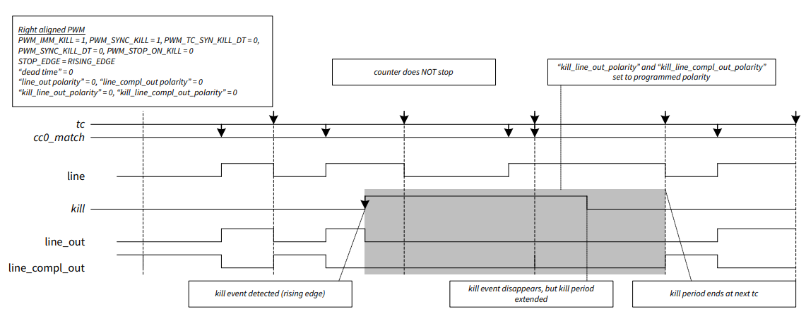
Additionally, the PWM kill signal can be connected to the ISR. In the ISR state machine, states can be handled. PWM kill has different modes of configuration to provide flexibility while integrating in the FOC solution.
ADC result monitoring
The ADC result monitoring mechanism can automatically compare the conversion result to a configured upper and a lower boundary value as shown in
Figure 22
and issue service requests based on predefined conditions. This feature can be utilized in the various protection mechanisms that minimize the CPU load.
Figure 22.
ADC result monitoring through limit checking
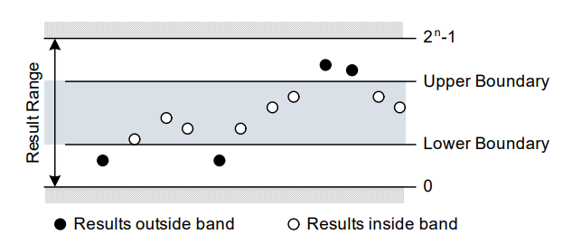
For example, during motor control, overvoltage and undervoltage faults can be handled using the ADC result monitoring feature without the need for software overheads.
Temperature sensor
The
PSOC™ Control C3
has an on-chip temperature sensor that is used to measure the internal die temperature. This on-chip temperature sensor can be used for cost-optimized MCU ambient temperature measurements.
Fast control loop
In the PMSM FOC solution, the fast control loop ISR is set up to execute the FOC current-control loop. If there is no fault in the system, this ISR reads the current, executes the FOC loop, and updates the PWM duty cycle.
Slow control loop
In the PMSM FOC solution, the TCPWM timer is set up to provide a slow control loop ISR. The slow control loop ISR is used by the state machine handling and other miscellaneous activities in the FOC algorithm.
Motor control solution personality
The motor control solution personality middleware can be accessed through ModusToolbox™ Library Manager as shown in
Figure 2
. After the addition of the library, the solution personality GUI will be available in the ModusToolbox™ Device Configurator, as shown in
Figure 23
.
Figure 23.
ModusToolbox™ solution personality
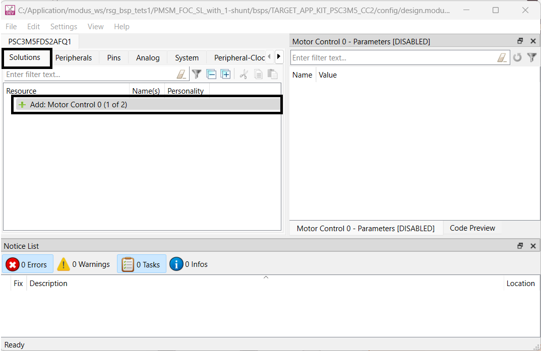
It can be used to configure the peripherals required for motor control functionality without the need to configure individual peripheral personality. Peripheral resources used by solution personality are marked reserved and cannot be edited by the individual personalities directly in the Device Configurator. The solution personality ensures resource conflict or provide feedback to fix it.
Solution personality uses is demonstrated using code example "
PMSM FOC SL with 3-shunt
" in the Infineon ModusToolbox™ ecosystem. This code example integrate the Infineon motor control library with solution personality-generated configuration and demonstrate the application.
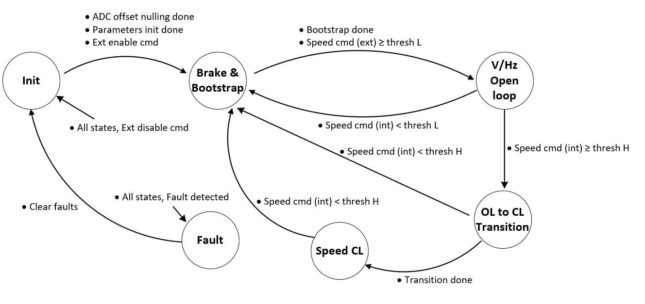
Motor state machine
The state entry function is called to enter in any state and similarly the corresponding state exit function is called to exit from a particular state. In each state, there are functions to call from fast control and slow control ISRs respectively. The structure of a state machine is as follows:
typedef struct
(
    STATE_t states[State_ID_Max];      //State call back functions
    STATE_ID_t current;                // Current state ID
    STATE_ID_t next;                   // Next state ID
    STATE_VARS_t vars;                 // State variables
    STATE_ADD_CALLBACK add_callback;   // Additional call back functions
) STATE_MACHINE_t;
The following state machine explain the different states of V/Hz start-up based FOC. Initialization function “STATE_MACHINE_Init ()”, enter the control into the “Init” state.
Figure 24.
State machine
Example software
This section describes the practical aspects of using the Infineon FOC solution on
PSOC™ Control C3
using the ModusToolbox™. ModusToolbox™ supports the "KIT_PSC3M5_MC1" kit and the associated code examples. Visit the
ModusToolbox™ software webpage
for more information and support.
Test setup
The test environment consists of a
PSOC™ Control C3
motor control drive card connected to an adapter board, a standard motor drive power board, USB-A to USB-C cable, power supply, and motor. The power board is rated at 250 W output power and 24 V input DC voltage.
Figure 25.
Test setup - KIT_PSC3M5_MC1
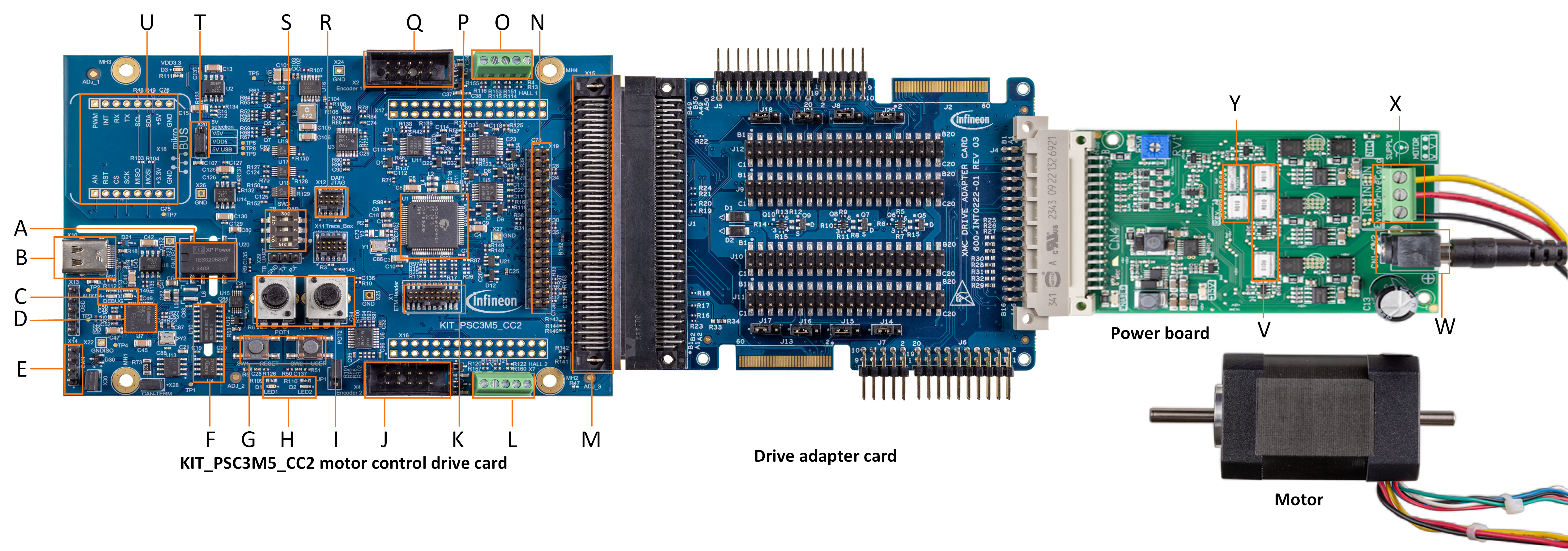
A - Isolated DC-DC (U20)
B - USB-C socket (X10)
C - DEBUG LED (D5) and AUX LED (D4)
D - XMC4200 MCU (J-Link - U7)
E - Isolated CAN header (X14)
F - SWD/UART and CAN isolators (U10, U4)
G - User button (SW2) and reset button (SW1)
H - User LED1 (D1) and user LED2 (D2)
I - Potentiometers (R6, R7)
J - Motor 2 encoder input (X4)
K - ETM header (X1)
L - Motor 2 Hall sensor input (X7)
M - 100-pin HD connector (X15)
N - MADK M5 pinout header (X19)
O - Motor 1 Hall sensor input (X3)
P - PSC3M5FDS2AFQ1 target MCU (U1)
Q - Motor 1 encoder input (X2)
R - 10-pin SWD/JTAG header (X12)
S - Debug interface selection (SW3)
T - Supply selection jumper (X20)
U - mikroBUS header (X18)
V - Three-phase shunt registers
W - DC power supply connector
X - Motor phase connector
Y - DC-link shunt register
Example code
Follow these steps to create the example project using ModusToolbox™.
Open Eclipse IDE for ModusToolbox™, create the workspace and select the launch
Select
New Application
in the Quick Panel
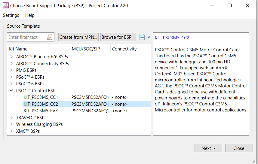
Select
KIT_PSC3M5_CC2
from PSOC™ Control BSPs and click
Next >
Figure 26.
BSP selection
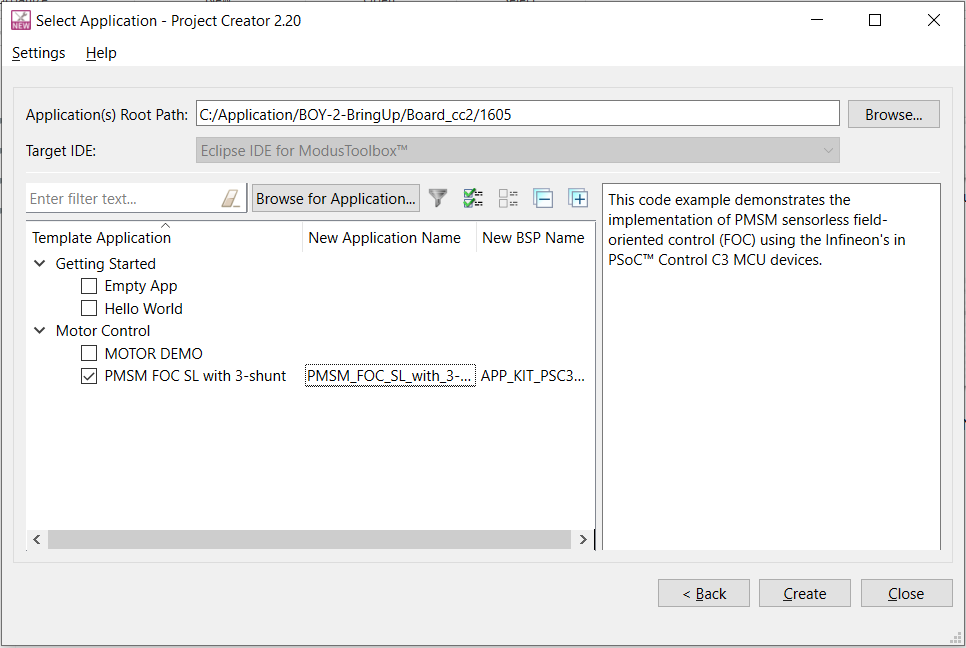
Select
PMSM FOC SL with 3-shunt
within the Motor Control to create a 3-shunt FOC project for KIT_PSC3M5_CC2 kit as shown in
Figure 27
Figure 27.
Code example selection
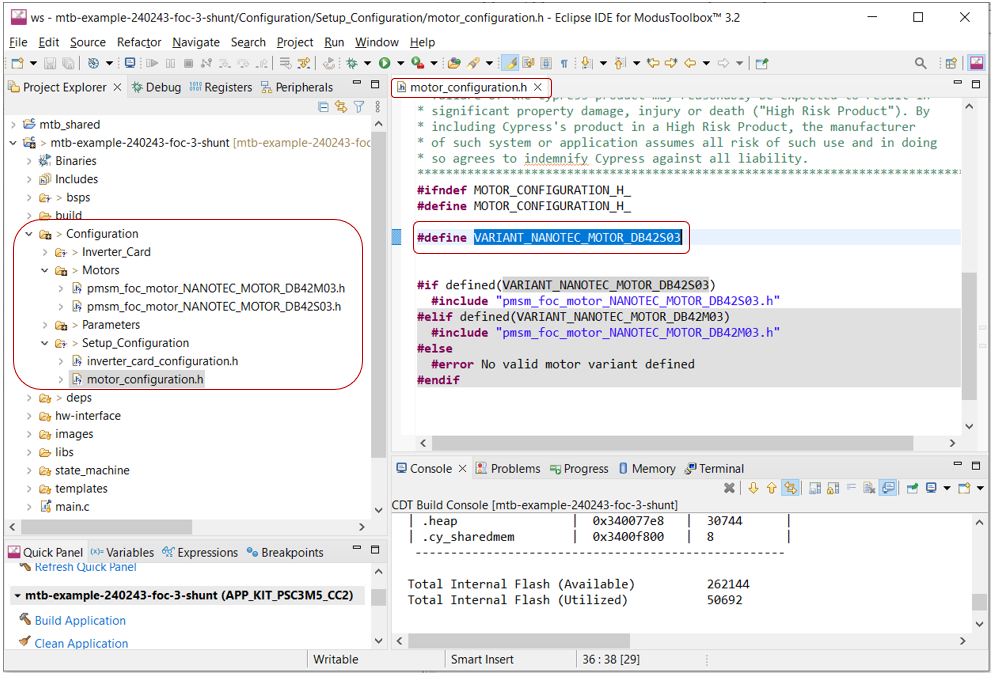
Test setup configuration
There is a configuration folder in the layered architecture of the code example to setup the motor and power board parameters. This folder has a predefined set of configuration parameters for motor and drives. Select the appropriate motor or drive card variant in the configuration file as shown in
Figure 28
.
Figure 28.
Test setup configuration
Peripheral configuration
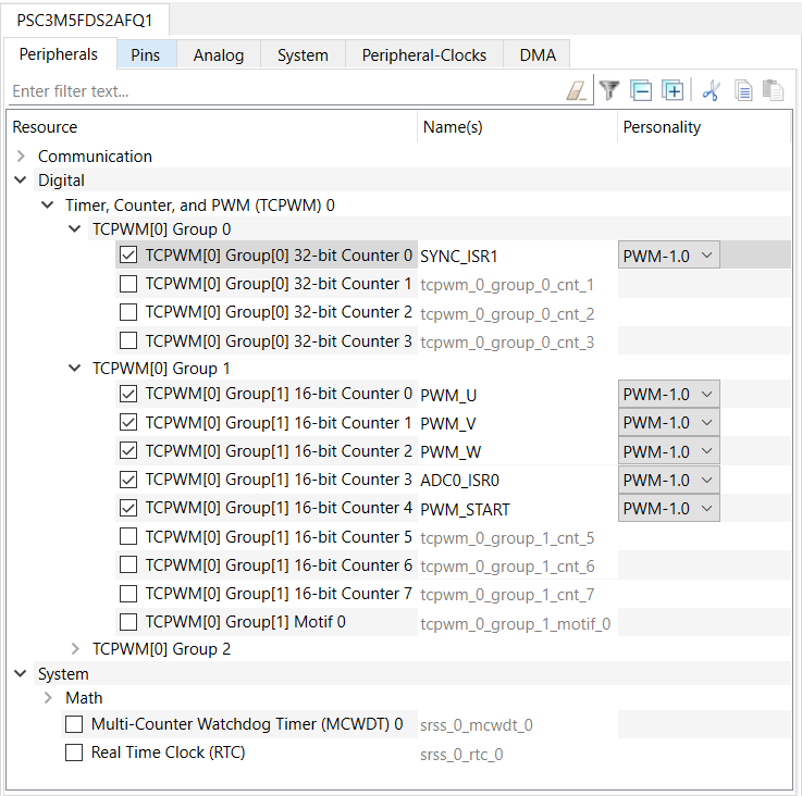
TCPWM configuration
A 3-shunt FOC consumes 6 TCPWM channels. Configuration details of each TCPWM has been provided in the following sections.
Figure 29.
TCPWM configuration
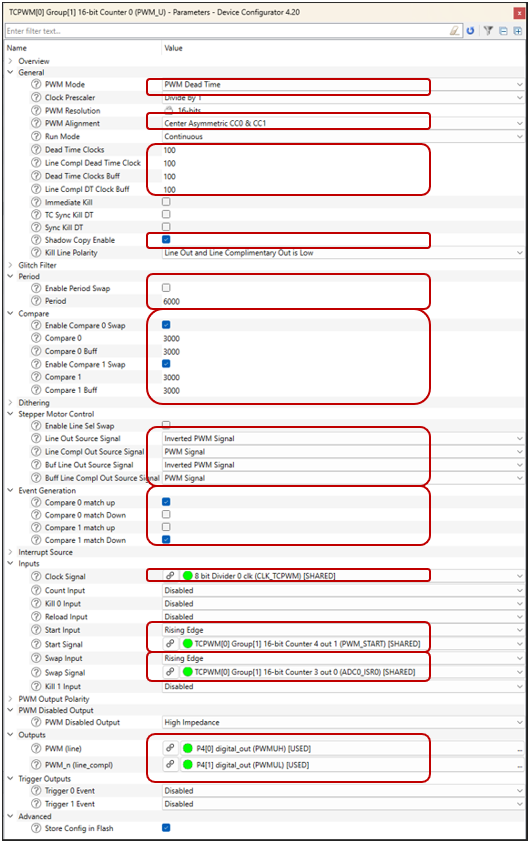
PWM timers (PWM_U, PWM_V, and PWM_W)
Start in sync and generate PWM signals to drive the motor
PWM pins are configurable
PWM frequency (fs0) 20 kHz
Figure 30.
PWM_U, PWM_V, and PWM_W timer configuration
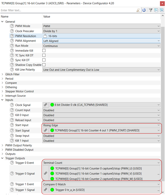
ADC0_ISR0
Start in sync with PWM_U, PWM_V, and PWM_W timer
Compare-0 match triggers the ADC group-0 (high priority group) for all the three-phase current conversion
Sampling frequency is 20 kHz. Since fpwm_fs0_ratio = 1U
Figure 31.
ADC0_ISR0 timer configuration
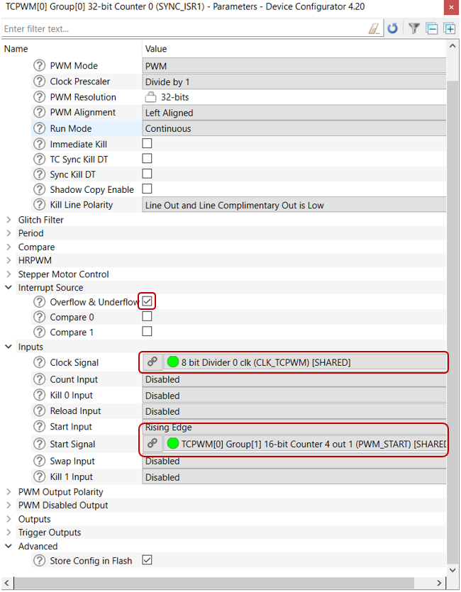
SYNC_ISR1
Start in sync with PWM timer, trigger source PWM_START timer
Overflow event connected to slow loop ISR
Default sampling frequency is 2 kHz ( fs0_fs1_ratio = 10U)
Figure 32.
SYNC_ISR1 timer configuration
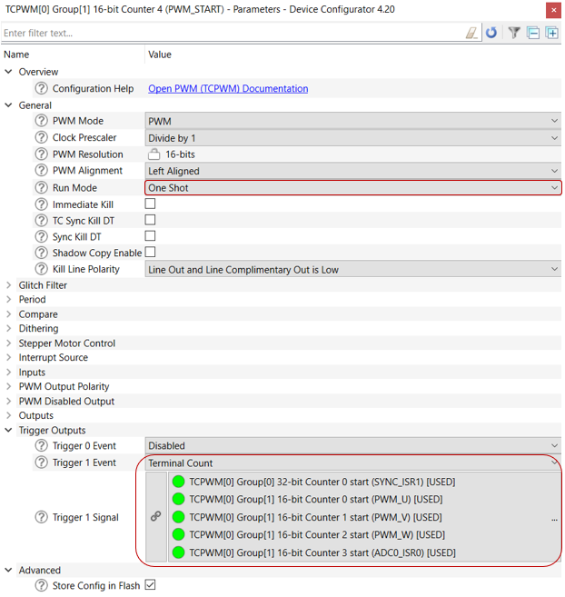
PWM_START
Configured in
One Shot
mode
Terminal count is connected to the start of other timers
Figure 33.
PWM_START timer configuration
ADC configuration
Enabled 6 ADC channels and assigned into two different groups, Group 0, and Group 1. Used direct channel sampler 0, 1, 2, and sampler 4 for phase U, phase V, phase W, and DC bus voltage respectively. Muxed sampler 0 and 2 used for potentiometer and temperature reading.
Figure 34.
ADC configuration
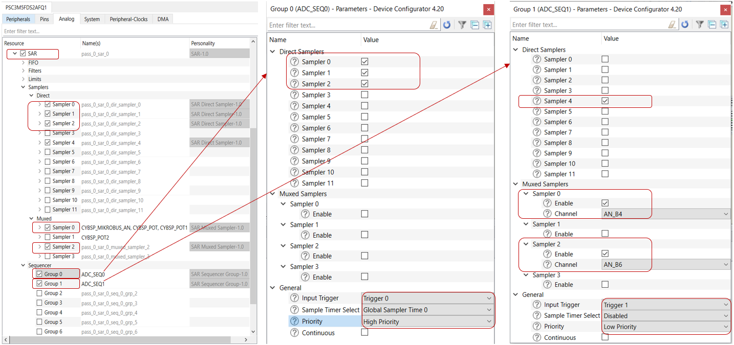
Group 0 property
High priority group
Trigger input: Hardware trigger
End of group conversion ISR executes the FOC loop (Fast loop)
Group 1
Low priority group
Trigger input: Firmware pulse
Peripheral configuration using solution personality
In ModusToolbox™, the solution personality is the alternate way to provide easy initialization of multiple peripherals required by the motor control application. After saving, the configuration data structure and APIs are generated and stored in the mcdi (motor control driver interface) folder, which are used by the motor control solution for selected topology. Configuration details are discussed in the following sections.
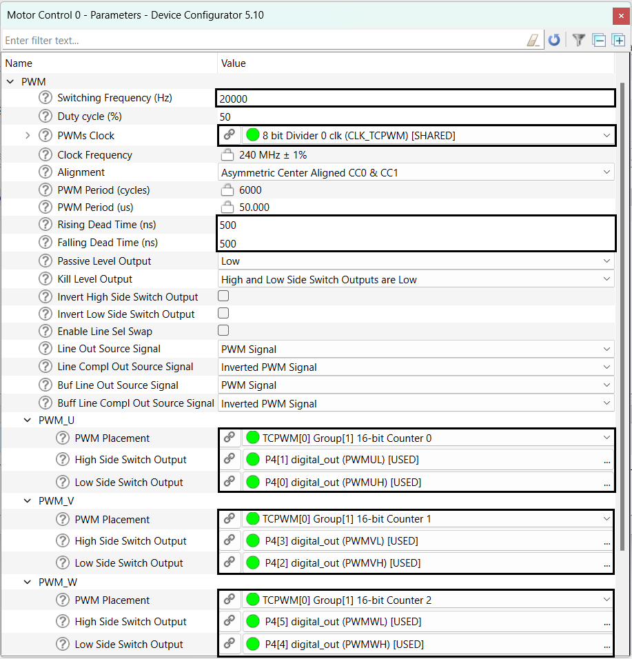
PWM configuration
In this section, the TCPWM timer is configured to generate six PWM outputs to drive the inverter module. Configurations are common to all the three PWM timers.
Figure 35.
PWM configuration
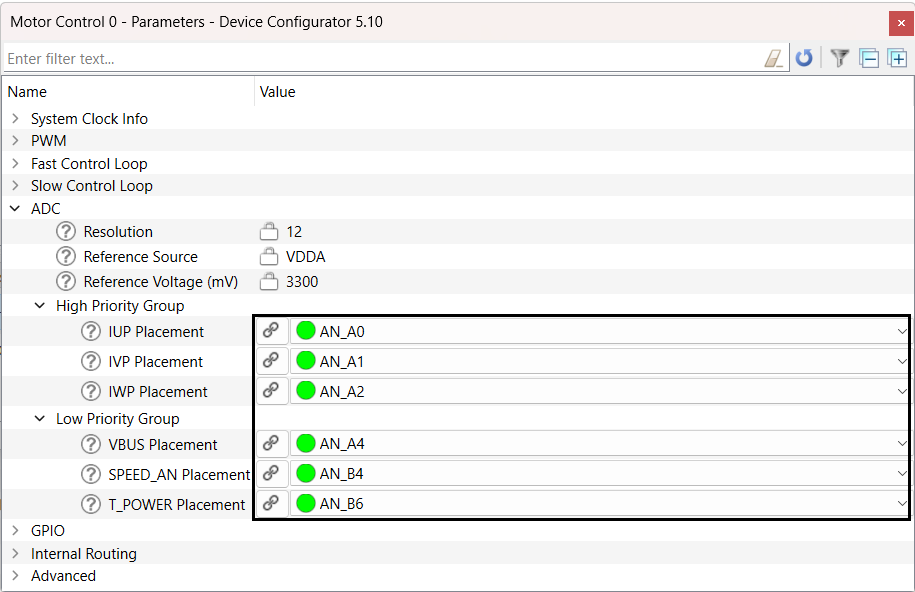
ADC configuration
This section configures the six analog pins to read the three-phase current, DC bus voltage, potentiometer for speed control, and temperature sense for protection.
Figure 36.
ADC configuration
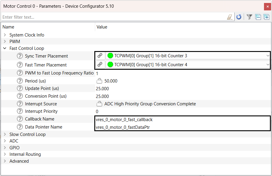
Fast control loop configuration
Sync timer - Provides swap trigger signal to PWM timers
Fast timer - Provides triggers to ADC. High priority group end of conversion generate fast control loop ISR
vres_0_motor_0_fast_callback - Fast control loop callback function (ISR)
vres_0_motor_0_fastDataPtr - Stores the result of three current channels
Figure 37.
Fast control loop configuration
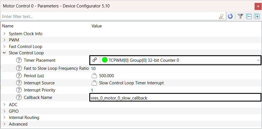
Slow control loop configuration
Slow control loop timer - Generates slow control loop ISR
vres_0_motor_0_slow_callback - Slows control loop callback function (ISR)
Figure 38.
Slow control loop configuration
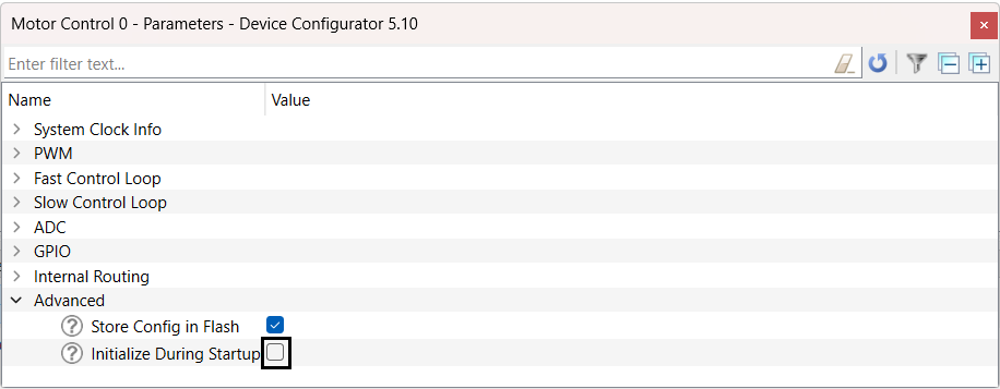
Peripheral initialization
An option available to enable and disable peripheral initialization during startup.
Figure 39.
Peripheral initialization during startup
Parameter configuration
This section describes the important parameters to spin the motor.
There are two ways to update the parameters either using the Motor Suite GUI or ModusToolbox™. If you are not using GUI, then ensure
PARAMS_ALWAYS_OVERWRITE
macro in
param.h
file is changed from false to true. Otherwise, any change in the
param.c
file will not be effective.
#define PARAMS_ALWAYS_OVERWRITE (true) // This will ensure parameters are always overwritten.
Basic and advanced parameters
There are a few basic parameters and advanced parameters which are derived from basic parameters. After proper configuration of basic parameters you can spin and control their PMSM or BLDC motors.
The following code shows the parameter structure of the motor control library. These parameters will be used for motor tuning and control.
Parameter structure
/* Motor parameters */
typedef struct
(
    float                  P;          // [#], Number of poles
    float                  lq;         // [H], q-axis inductance
    float                  ld;         // [H], d-axis inductance
    float                  lam;        // [Wb], permanent magnet's flux linkage
    float                  r;          // [ohm], stator resistance
    float                  T_max;      // [Nm], maximum torque
    float                  i_cont;     // [A], continuous current rating
    float                  i_peak;     // [A], peak current rating
    float                  id_max;     // [A], maximum demagnetization current
    float                  v_nom;      // [Vpk-ln], nominal voltage peak, line to neutral
    ELEC_t                 w_nom;      // [Ra/sec-elec], nominal speed
    ELEC_t                 w_max;      // [Ra/sec-elec], maximum speed
    float                  zeta;       // [#], saliency ratio = lq/ld
    I2T_PARAMS_t           i2t;
) MOTOR_PARAMS_t;
/* System parameters */
typedef struct
(
    SAMPLE_PARAMS_t       samp;       // [], sampling parameters
    LUT_PARAMS_t          lut;        // [#], luts
    ANALOG_SENS_PARAMS_t  analog;     // [], analog sensor parameters
    RATE_LIM_PARAMS_t     rate_lim;   // [], rate limiter parameters
    FAULT_PARAMS_t        faults;     // [], fault parameters
    CMD_PARAMS_t          cmd;        // [], command parameters
    FB_PARAMS_t           fb;         // [#], feedback parameters
    float                 boot_time;  // [sec], time for charging bootstrap capacitors
    float                 vdc_nom;    // [], dc bus voltage parameters
) SYS_PARAMS_t;
/* Parameter configuration structure*/
typedef struct
(
    PARAMS_ID_t           id;
    MOTOR_PARAMS_t        motor;
    SYS_PARAMS_t          sys;
    OBS_PARAMS_t          obs;
    MECH_PARAMS_t         mech;
    FILTER_PARAMS_t       filt;
    CTRL_PARAMS_t         ctrl;
) PARAMS_t;
/*Parameter Configuration Object*/
PARAMS_t params
The basic parameters are divided into multiple categories, such as:
Motor parameters:
params.motor
System parameter:
params.sys
Observer parameters:
params.obs
Motor mechanical parameters:
params.mech
Filter parameters:
params.filtand
Control parameters:
params.ctrl
Motor parameters
motor.P
represents the number of poles
The current values are based on the peak values, not rms
motor.i_cont
is the continuous current rating of the motor
motor.i_peak
is the peak current rating of the motor. Set this value to 2.5 to 3x of
motor.i_cont
, if not specified in the motor datasheet
    params.motor.P          = 8.0f; // [#]
    params.motor.lq         = 670.0E-6f; // [H]
    params.motor.ld         = 670.0E-6f; // [H]
    params.motor.lam        = 6.0E-3f; // [Wb]
    params.motor.r          = 450.0E-3f; // [Ohm]
    params.motor.T_max      = 0.390f; // [Nm]
    params.motor.i_peak     = 10.80f; // [A]
    params.motor.i_cont     = 3.50f; // [A]
    params.motor.id_max     = 1.75f; // [A]
    params.motor.v_nom      = LINE_TO_PHASE(24.0f); // [Vpk-ln]
    params.motor.w_nom.elec = MECH_TO_ELEC(HZ_TO_RADSEC(RPM_TO_HZ(4000.0f)), params.motor.P);
    params.motor.w_max.elec = MECH_TO_ELEC(HZ_TO_RADSEC(RPM_TO_HZ(6000.0f)), params.motor.P);
System parameters
Set the shunt type to three shunts or single shunt based on inverter setup
Set the current sensing opamp gain based on the inverter setup
hyb_mod.adc_t_min
and
hyb_mod.ki
belong to single shunt-based control
shunt.res
is a key parameter and represents the shunt value for both single shunt and three shunt control. The value is set in the
MotorCtrlHWConfig.h
file
Sampling parameters
cmd.w_max.mech
is the maximum motor speed controlled by a potentiometer. For example, set
motor.w_max.elec
to 6000 rpm but if you set
cmd.w_max.mech
to 3000 rpm, then maximum motor speed using potentiometer would be 3000 rpm instead of 6000 rpm
vdc_nom
is the power supply voltage. Ideally, this number is the same as the
motor.v_nom
. However, you can apply 24 V to a 48 V motor. To get this, set
vdc_nom
as 24 V rather than 48 V.
Command parameters:
The default source of speed control is a potentiometer. It can be changed to external source
    params.sys.samp.fs0	           = 15.0E3;  // PWM frequency
    params.sys.samp.fpwm_fs0_ratio = 1U;     // ISR-0 to PWM frequency ratio (1x slower)
    params.sys.samp.fs0_fs1_ratio  = 15U;    // ISR-1 to ISR-0 ratio (15x slower)
params.sys.cmd.w_max.mech = HZ_TO_RADSEC(RPM_TO_HZ(4000.0f));
params.sys.vdc_nom = 24.0f;
params.sys.cmd.source = Potentiometer;
Observer parameters
Setting the observer parameters are important for sensorless FOC operation.
w_thresh.elec
is the speed at which the transition from open loop to close loop FOC happens. This is a key parameter to tune if the transition to closed loop does not happen smoothly
lock_time
is the time expected for the observer to lock to the rotor angle, to be tuned as required
    params.obs.w_thresh.elec = params.motor.w_nom.elec * 0.20f;
    params.obs.lock_time     = 0.500f;
Mechanical parameters
The mechanical parameters cannot be found in the motor datasheet. They depend mostly on the mechanical load attached to the motor’s shaft. It is best to derive and set them properly.
    params.mech.inertia  = 1.1E-5f;
    params.mech.viscous  = 1.2E-5f;
    params.mech.friction = 6.0E-3f;
Control parameters
Control parameters are divided into subcategories as follows:
Control mode:
Multiple control modes are available to select in the firmware. You can set the control mode in
param.c
file. Configuration options are available in the
param.h
file
Speed controller
speed.bw
is a key parameter for the speed loop controller. Kp and Ki for the controller are automatically calculated from the given bandwidth and motor mechanical parameters in the function
PARAMS_InitAutoCalc()
Current controller
ctrl.curr.bw
is a key for the current loop controller. Kp and Ki for the controller are automatically calculated from motor electrical parameters including stator inductance and resistance in function
PARAMS_InitAutoCalc()
. Set the value of
ctrl. curr.bw
at least 3~5 times lower than the switching frequency. In addition, set it to be higher than
speed.bw
Voltage controller
The following parameters are the key to start spinning the motor
w_thresh.elec
is the minimum speed that will activate open loop voltage control. Any speed commanded under this threshold will not spin the motor
v_min
is the minimum voltage that needs to apply right before the motor start spinning in an open loop
v_to_f_ratio
is the V/F constant required to spin a motor in an open loop.
Modulation method configuration
params.ctrl.mode = Speed_Mode_FOC_Sensorless_Volt_Startup;
params.ctrl.speed.bw = HZ_TO_RADSEC(15.0f);
params.ctrl.curr.bw = HZ_TO_RADSEC(750.0f); // [Ra/sec]
params.ctrl.volt.w_thresh.elec = params.motor.w_nom.elec * 0.05f;
params.ctrl.volt.w_hyst.elec = params.ctrl.volt.w_thresh.elec * 0.5f;
params.ctrl.volt.v_min = 0.15f;
params.ctrl.volt.v_to_f_ratio = 7.5E-3f;
params.ctrl.volt.mod_method=Space_Vector_Modulation;
ModusToolbox™ Motor Suite
ModusToolbox™ Motor Suite is a GUI integrated with the ModusToolbox™ ecosystem to configure, control, and monitor the motor control parameters.
GUI has two options to flash the firmware onto the target board.
Option-1 (default): Flash the default executable
Option-2: Compile the project and flash the custom executable
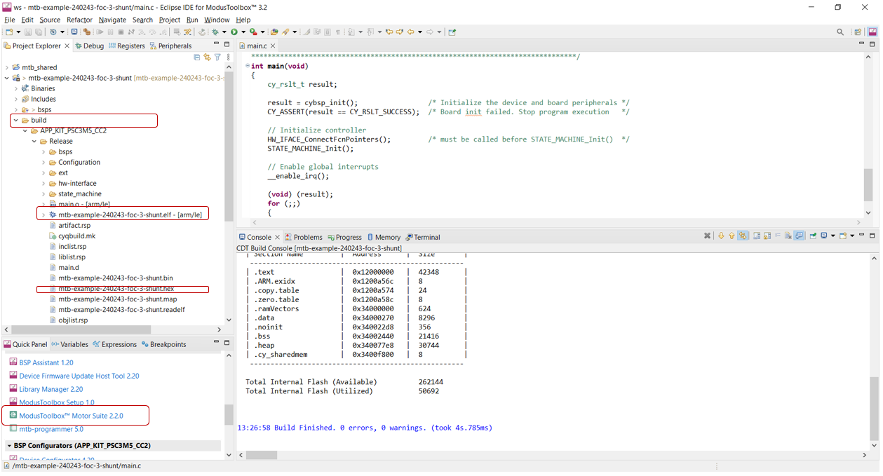
GUI can be installed from
Infineon Developer Center (IDC)
or launch from ModusToolbox™ Quick Panel (highlighted) in the bottom-left corner shown in
Figure 40
.
Figure 40.
GUI launch panel
Double-click on ModusToolbox™ Motor Suite in the Quick Panel, a new window opens as shown in
Figure 41
.
Figure 41.
ModusToolbox™ Motor Suite
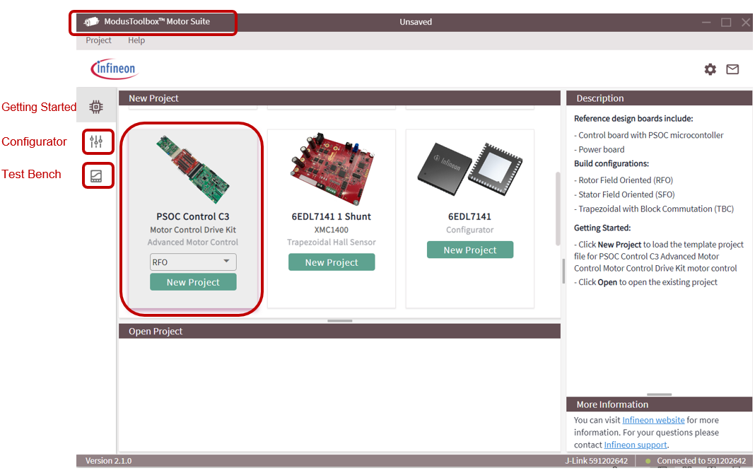
Select the PSOC™ Control C3 motor control drive kit and create a new project. The configurator page will pop-up with an addition icon for the Test Bench.
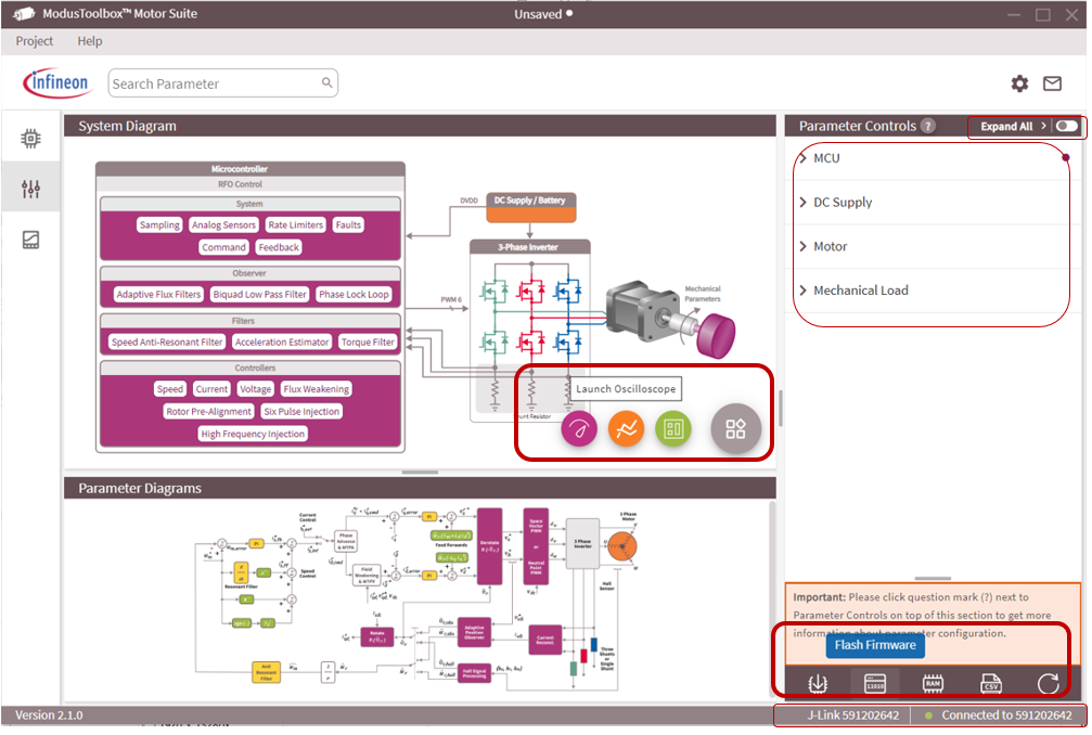
Configurator
ModusToolbox™ Motor Suite Configurator provides the following:
Displays the J-Link connection establishment in the right bottom corner indicated by a green LED
Flash Firmware option for default as well as custom executable
Static parameter configuration for motor control application
Option to launch the oscilloscope
Figure 42.
Configurator
For more details, click
Help
in the left top corner of the window.
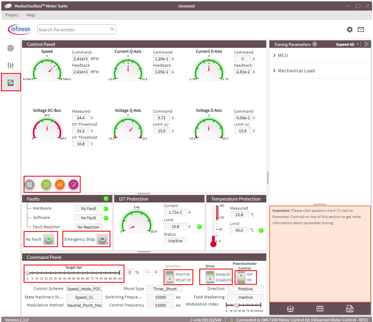
Test Bench
Test Bench provide the run time control and monitor of the motor parameters.
Control parameters
Drive:
Enable/disable the drive
Potentiometer:
Switch on to control motor speed using a potentiometer (hardware)
Switch off to control motor speed using the
Target Set
slider in the GUI
Direction:
Change the motor direction
Emergency Stop:
Stop and reset
Figure 43.
Motor Test Bench
Oscilloscope
ModusToolbox™ Motor Suite support a high-speed oscilloscope to monitor any firmware variable, at a time it monitors up to four variables. In the oscilloscope window, configure the
Divider
value and select
Auto Scale
to get the optimum resolution.
Figure 44.
Oscilloscope
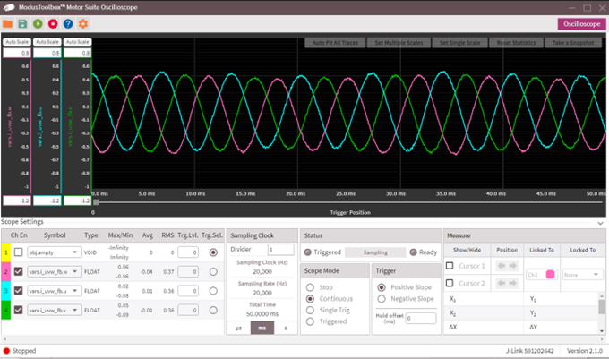
In the
Figure 44
, three motor phase current has been monitor while Channel 1 is unused. Channel 2, channel 3, and channel 4 are used for phase current vars.i_uvw_fb.w, vars.i_uvw_fb.u, and vars.i_uvw_fb.v respectively.
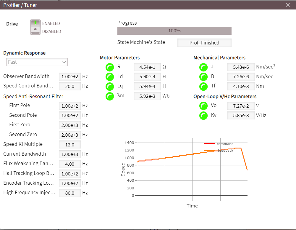
Motor profiler
The motor profiler estimates the following electrical and mechanical parameters of the motor.
Electrical parameters
Stator inductance both d and q axis
Stator resistance, and
Rotor flux
Mechanical parameters
Inertia (J)
Viscous friction coefficient (B)
Coulomb friction (Tf)
Additionally, the motor profiler calculates the open-loop V/Hz constant as well.
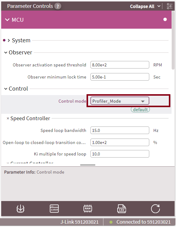
To use a motor profiler, configure the control mode as
Profiler_Mode
from the dropdown menu in the configurator view of Motor Suite as shown in
Figure 45
.
Figure 45.
Motor profiler mode configuration
Select the test bench view of Motor Suite and launch the
Profiler/Tuner
to run the motor profiler.
Profiler provides the option to select the dynamic response of the speed control loop. There are three options available: Slow, Moderate, and Fast as shown in
Figure 46
.
Figure 46.
Motor profiler
Summary
This application note shows how to develop the sensorless FOC scheme in a straightforward hardware and software implementation with the
PSOC™ Control C3
. It is indeed possible to integrate HPPASS and TCPWM so that the timing and synchronization required by the complexity is accommodated.
The capabilities of the
PSOC™ Control C3
are demonstrated by the easy-to-use PMSM sensorless FOC code examples that can be downloaded through the ModusToolbox™. FOC code example is a useful starting point for developing typical applications, you can set up, personalize, and optimize the scheme to its own use cases.
References
Contact
Infineon Support
to obtain these documents.
Application notes
Datasheet
002-36422
- PSOC™ Control C3 MCU - PSC3P2xD, PSC3M3xD
Reference manuals
Hardware design files
KIT_PSC3M5_CC2
- PSOC™ Control C3 motor drive card