PSOC™ Control C3 architecture reference manual
Reference manual
About this document
Scope and purpose
This document provides comprehensive information about Infineon's
PSOC™ Control C3
series of microcontrollers. These 32-bit, single-core chips are part of a high-performance, low-power, and secure family of MCUs specifically designed for real-time control, enhanced sensing, secure, and low-power applications.
Intended audience
This document is intended for hardware engineers, embedded software developers, and system architects who want to understand the architecture of Infineon's
PSOC™ Control C3
series of microcontrollers.
Introduction
This document provides information about Infineon's
PSOC™ Control C3
series of microcontrollers designed for industrial applications. These microcontrollers feature an Arm® Cortex®-M33 CPU and integrated programmable peripherals. Specifically designed for real-time applications, they are manufactured using an advanced 40-nm process. Additionally, they offer a range of low-power modes, security features, a flexible clocking system, rich communication peripherals, advanced digital and analog peripherals, and compatibility with industry-standard development tools.
Detailed features
This device has the following features:
CPU subsystem
Arm® Cortex®-M33 running up to
180 MHz
Digital signal processor (DSP), floating-point unit (FPU), memory protection unit (MPU), 16 KB I-cache
Two direct memory access (DMA) controllers with 16 channels each
Security
Platform security architecture level 2 (PSA L2) certified
Step-wise authentication of execution images until the control is handed over to the user code
Secure execution of code in the execute-only mode for protected routines
Image authentication and integrity check
TrustZone framework that establishes an isolated device root of trust (RoT) for trust attestation and software management
Memory
On-chip flash with ECC support
Up to 256-KB flash with read while write (RWW) capability, 64 KB ROM for boot code, and bootloader functions
Built-in device firmware upgrade (DFU) support in boot ROM via serial interface (UART/I2C/SPI)
SRAM with ECC support
64 KB
full SRAM available in Deep Sleep
SRAM data path is protected with a hardware mechanism (ECC) for soft error detection and correction
Clocking subsystem
8 MHz IMO with Deep Sleep operation offering ±2% accuracy
48 MHz internal high-frequency oscillator (IHO) offering ±1% accuracy
32 kHz internal low frequency oscillator (ILO) offering ±10% accuracy
4 to 35 MHz external crystal oscillator (ECO) support
32.768 kHz external watch crystal oscillator (WCO) usable for real-time clock (RTC)
External clock (EXTCLK): Maximum frequency 80 MHz
One frequency lock loop (FLL) with 24-100 MHz output range
Two digital phase-locked loops, DPLL#0 and DPLL#1, with 25-250 MHz output range
Low power (1.71 V to 3.6 V) operation
Six power modes (Active, Sleep, Deep Sleep, Deep Sleep-RAM, Deep Sleep-OFF, and Hibernate) for fine-grained power management
Deep Sleep mode current of 11 µA at 3.3-V external supply using an internal voltage regulator with 64-KB SRAM retention, LPComp, and Deep Sleep SCB
Hibernate mode current with RTC and LPComp of up to 1000 nA
Communication peripherals
Serial communication blocks (SCBs)
Up to six independent run-time-reconfigurable SCBs; each is software-configurable as I2C, SPI, or UART in master or slave mode
One SCB also supports Deep Sleep operation and wake-up from Deep Sleep in I2C slave and SPI slave modes
One SCB has fast SPI support of up to 50 MHz
SCB supports single-wire half-duplex mode for UART
CAN FD
Up to two CAN FD channels with a single instance with operation of up to 8 Mbps
High-performance, programmable analog subsystem (HPPASS)
Analog-to-digital converter (ADC)
One 12-bit,
12-Msps
SAR ADC
Up to 16 dedicated analog pads, connected to up to 16 parallel sample stages
Two additional GPIOs can be used as analog inputs
Up to 16 sample/hold (S/H) circuits in SAR ADC connected to pins directly or through AMUX
One S/H circuit in SAR ADC is internally connected to analog references and a temperature sensor
Configurable input gain of 1, 3, 6, and 12 on all 16 S/H circuits
Digital comparator at the output to compare the ADC result against programmed boundary values
Digital comparator outputs can be connected to timer/counter pulse-width modulator (TCPWM) (low latency between the modules)
Analog comparators
Five Active comparators without Deep Sleep functionality, each with a 10-bit DAC to generate the comparator reference
Each comparator supports an external reference/threshold through pins
Active comparator can be used with the built-in DAC in Hysteresis mode
Two additional comparators in LPComp are available in Active/Deep Sleep/Hibernate modes
Comparator outputs can be brought to pins for control loop applications
Comparator outputs can be connected to TCPWM (low latency between the modules)
Logical OR of multiple comparator trigger outputs connected as an input trigger to TCPWM via trigger MUX
Real-time control peripherals
Coordinate rotation digital computer (CORDIC)
Supports all CORDIC operating modes for solving circular (trigonometric), hyperbolic functions, and integrated independent lookup tables to accelerate calculation
Timer/counter pulse-width modulator (TCPWM)
Sixteen 16-bit TCPWM channels
Four 32-bit TCPWM channels
supporting high-resolution PWM generation (HRPWM) for PWM outputs
Center-aligned, edge, and pseudorandom modes
Comparator-based triggering of kill signals
Shadow update of duty, period, dead-time, output signal polarity, and dithering (pseudorandom mode)
Multichannel control: In a group of eight TCPWM channels, one channel within a group can trigger another channel
Ability to logically combine the outputs of multiple channels through Smart I/O
Dedicated output triggers mux in a group to allow flexibility to the PWM channel as a trigger and/or gate signals to the HPPASS
Hall sensor interface with autonomous BLDC block commutation support
Quadrature encoder interface to decode motor speed and rotor position
HRPWM feature for period, duty, and dead-time insertion with a typical resolution of less than 80 ps
I/O subsystem
Programmable GPIO pins
Up to
66
functional pins (
50
digital GPIOs; 2 out of
50
GPIOs can be used for analog inputs + 16 dedicated analog-only inputs)
Programmable drive modes, strengths, and slew rates
Programmable digital
Up to
seven
Smart I/O capable ports (
I/Os, 56 LUTs) enable Boolean operations on I/O signals
Cryptography
Cryptography accelerator
Hardware acceleration for symmetric (AES-128) and asymmetric cryptographic algorithms (RSA and elliptic curve cryptography (ECC)) supported by vector unit (VU) and hash functions (SHA-256)
True random number generator (TRNG) function
Architecture
Figure 1.
Functional block diagram
Document organization and conventions
Major sections
The information in this reference manual is organized as follows:
Chapter – Presents the chapters specific to an individual aspect of the device. These are the detailed implementation and use information for some aspect of the integrated circuit
Registers summary – Summary of registers associated with the chapter
Registers Reference Manual - Supplies all device register details summarized in the reference manual. This is an additional document
Document conventions
Register conventions
Register conventions are detailed in the Registers Reference Manual.
Numeric naming
Hexadecimal numbers are represented with all letters in uppercase with an appended lowercase ‘h’ (for example, ‘14h’ or 3Ah) and hexadecimal numbers may also be represented by a ‘0x’ prefix, the C coding convention. Binary numbers have an appended lowercase ‘b’ (for example, 01010100b or 01000011b’). Numbers not indicated by an ‘h’ or ‘b’ are decimal.
Unit of measure
lists the units of measure used in this document.
Abbreviation | Unit of measure |
|---|---|
bps | bits per second |
°C | degrees Celsius |
dB | decibels |
dBm | decibels-milliwatts |
fF | femto farads |
G | Giga |
Hz | Hertz |
k | kilo, 1000 |
K | kilo, 2^10 |
KB | 1024 bytes, or approximately 1000 bytes |
Kbit | 1024 bits |
kHz | kilo Hertz (32.000) |
kΩ | kilo Ohms |
MHz | mega Hertz |
MΩ | mega Ohms |
µA | micro Amperes |
µF | micro Farads |
µs | micro seconds |
µV | micro volts |
µVrms | micro volts root-mean-square |
mA | milli amperes |
ms | milli seconds |
mV | milli Volts |
nA | nano Amperes |
ns | nano seconds |
nV | nano Volts |
Ω | ohms |
pF | pico Farads |
pp | peak-to-peak |
ppm | parts per million |
SPS | samples per second |
σ | sigma: one standard deviation |
V | Volts |
Acronyms
lists the acronyms and their definitions.
Acronym | Definition |
|---|---|
AC | Autonomous controller |
ACK | Acknowledge |
ADC | Analog-to-digital converter |
AES | Advanced Encryption Standard |
AF | Analog filter |
AHB | AMBA high-performance bus, an Arm® ® data transfer bus |
AIRCR | Application interrupt and reset Control Register |
AMBA | Advanced Microcontroller Bus Architecture |
ARB | Arbitration |
BGR | Band gap reference |
BOD | Brown-out detect |
CAN | Controller area network |
CAN-FD | Controller area network flexible data-rate |
CC0 | Capture/Compare0 |
CC1 | Capture/Compare1 |
CM-33 | Cortex® M33 |
CORDIC | Coordinate Rotation Digital Computer |
CPU | Central processing unit |
CPUSS | CPU subsystem |
CSG | Comparator and slope generator |
CSV | Cock supervision |
CTS | Clear to Send |
DAC | Digital-to-analog converter |
DAP | Debug access port |
DF | Digital filter |
DMA | Direct memory access |
DMAC | Direct memory access controller |
DPLL | Digital phase-locked loop |
DSI | Digital system interconnect |
DSP | Digital signal processing |
DU | Data unit |
DW | Data wire |
ECC | Error correcting code |
ECO | External crystal oscillator |
Em_EEPROM | Emulated Electrically Erasable Programmable Read-only Memory |
EOC | End of conversion |
EPPB | External private peripheral us |
FIFO | First in first out |
FIR | Finite impulse response |
FLL | Frequency locked loop |
FM | Flash macro |
FPU | Floating point unit |
FSM | Finite-state machine |
GPIO | General-purpose input output |
HPPASS | High-performance programmable analog subsystem |
HRPWM | High-resolution PWM |
HSIOM | High-speed I/O matrix |
I2C | Inter-integrated circuit |
I-Cache | Instruction cache |
ICER | Interrupt clear enable register |
IDAU | Implementation defined attribution unit |
IHO | Internal high-speed oscillator |
ILO | Internal low-speed oscillator |
IMO | Internal main oscillator |
INFRA | Infrastructure |
IOSS | I/O subsystem |
IPC | Inter processor communication |
IRQ | Interrupt request |
ISER | Interrupt set enable register |
ISR | Interrupt service routine |
ITNS | Interrupt target non-secure |
LCS | Life cycle stage |
LDO | Low dropout |
LFCLK | Low frequency clock |
LIN | Local interconnect network |
LP | Low power |
LPCOMP | Low-power comparator |
LUT | Look-up table |
LVD | Low-voltage detect |
MCU | Microcontroller unit |
MCWDT | Multi-counter watchdog timer |
MF | Medium frequency |
MISO | Master in slave out |
MMIO | Memory-mapped I/O |
MOSI | Master out slave in |
MOTIF | Motion interface |
MPC | Memory protection controller |
MPS | Magnitude PreScaler |
MPU | Memory protection unit |
MSC | Master security controller |
MSP | Main stack pointer |
MTQ | Minimum time quantum |
NACK | No acknowledgment |
NMI | Non-maskable interrupt |
NVIC | Nested vectored interrupt controller |
NVM | Nonvolatile memory |
OD | Overdrive |
OTP | One-time programmable |
OV | Over flow |
PC | Protection context |
PDL | Peripheral driver library |
PendSV | Pending supervisory |
PERI | Peripheral interconnect |
PID | Protected identifier |
PLL | Phase-locked loop |
POR | Power-on reset |
PPB | Private peripheral bus |
PPC | Peripheral protection controller |
PPU | Power policy unit |
PSP | Process stack pointer |
PSR | Program and status register |
PWM | Pulse width modulation |
PWMDT | Pulse width modulation with dead time insertion |
RAM | Random access memory |
RMA | Return merchandise authorization |
RTC | Real time clock |
RTS | Request to send |
RX | Receive |
SAR | Successive approximation register |
SAU | Secure attribution unit |
SCB | Serial communication block |
SCL | Serial clock |
SDA | Serial data |
SFR | Special function register |
SHA | Secure hash algorithm |
SoC | System on-chip |
SPI | Serial peripheral interface |
SRAM | Static random access memory |
SRAMC | Static random access memory controller |
SRSS | System resource subsystem |
SVCall | Supervisory call |
SWD | Single-wire debug |
TC | Terminal count |
TCPWM | Timer counter pulse width modulation |
TQ | Time quantum |
TRNG | True random number generator |
TX | Transmit |
UART | Universal asynchronous receiver/transmitter |
UART_MP | UART multi-processor |
ULP | Ultra low power |
UN | Underflow |
VTOR | Vector table offset register |
VU | Vector unit |
WCO | Watch crystal oscillator |
WDT | Watchdog timer |
WFE | Wait for event |
WFI | Wait for interrupt |
WIC | Wake-up interrupt controller |
WS | Wait states |
XRES | External reset |
CPU subsystem (CPUSS)
The CPU subsystem is based on the 32-bit Arm® Cortex®-M33 (CM33) CPU. It is designed for security, control, communication, short interrupt response time, high code density, and high 32-bit throughput while maintaining a strict cost and power consumption budget.
This section provides only an overview of the Arm Cortex® CPU in
PSOC™ Control C3
MCU. For details, see the Arm documentation sets for
cortex®-M33
.
Features
The
PSOC™ Control C3
MCU Arm® Cortex®-M33 (CM33) CPU has the following features:
Maximum clock frequency of 180 MHz @ over drive (OD) mode
Single-precision floating-point unit (FPU) and DSP extension
Memory protection unit (MPU) with up to 8 regions per security state (secure and non-secure)
Nested vectored interrupt controller (NVIC) integrated with the CPU core yielding low interrupt latency
Wakeup interrupt controller (WIC) that allows the CPU to wake up from the Deep Sleep power mode through Deep Sleep interrupts
16 KB instruction cache (I-cache) on Cortex®-M33 C-AHB bus with four-way set associativity
Supports TrustZone-M memory mapping for secure/non-secure aliasing based on programmable secure attribution unit (SAU) and a fixed implementation defined attribution unit (IDAU)
Architecture
CM33 is a 32-bit processor with a 32-bit data path, 32-bit registers, and a 32-bit memory interface. The CPU supports a wide variety of instructions in the thumb instruction set. The CM33 CPU supports thread and handler operating modes (refer to the
Operating modes and privilege levels
section). Additionally, the CM33 CPU supports secure and non-secure security states based on the security extension.
The CM33 instruction set includes:
Signed and unsigned, 32×32 -> 32-bit and 32×32 -> 64-bit, multiply and multiply accumulate, all single-cycle
Signed and unsigned 32-bit divides that take 2 to 11 cycles (depending on values)
DSP instructions
Complex memory load and store access
Complex bit manipulation
The CM33 processor with FPU supports single precision arithmetic as defined by the FPv5 architecture. This is compliant with the ANSI/IEEE Std 754-2008, IEEE standard for binary floating-point arithmetic.
CPUSS
The
PSOC™ Control C3
CPUSS is a security, control, and communication CPU that is built on a Cortex®-M33 (CM33) core and runs at up to 180 MHz.
The CM33 CPU is a 3-stage pipeline (3PIP) from Arm® based on the Arm® v8-M architecture having a low-power domain with rapid clock switching. The CPUSS implements Arm® TrustZone-M compatible security and protection infrastructure. It provides the initial boot for security and protection schemes.
The CM33 CPU is a TrustZone-M CPU that implements an inbuilt security extension. As part of the security extension, the CM33 implements a secure attribution unit (SAU) inside the CPU. The TrustZone-M architecture also defines an external interface to the CPU, which can be connected to an implementation defined attribution unit (IDAU)
For non-CPU masters in CPUSS, a master security controller (MSC) is instantiated along with an implementation defined attribution unit (IDAU) to distinguish secure/non-secure transfers. For more details, refer to the TrustZone section
The CPUSS has a 16 KB 4-way set associative instruction cache on the C-AHB bus. CPUSS supports on-chip SRAM controller and memories. It provides C-AHB bus access from SRAM for code execution. The CPUSS includes a 128-bit AHB5 bus interface for instruction fetch and data access from FLASH (NVM), as well as internal SRAMs, which are accessible on their aliased addresses. Also it supports a 32-bit AHB5 bus interface to access the memory-mapped Flash, internal SRAM present in the system memory map.
The CPUSS includes two DMA controllers supporting 16 channels with Arm® Q-channel support. These channels are primarily used to service the SCB, CORDIC, and TCPWM peripherals. The CPUSS includes four inter-processor communication (IPC) hardware for secure and non-secure applications to communicate and synchronize their activities.
The CPUSS has clk_hf0 clock domain for the majority of hardware modules.
clk_hf0: Up to 180 MHz @ 1.2 V. Used by majorities of the CPUSS including I-Cache, AHB bus infrastructures, DMA, MSC/IDAU/MPC, and all on-chip memory controllers running at a single synchronous frequency
The CPUSS implements a centralized fault reporting infrastructure (only a single fault interrupt handler is required), which captures faults related to (not an exclusive listing) MPC/PPC violations, peripheral-specific errors, memory controller-specific errors such as ECC errors, and time-out errors.
In CPUSS, the active power domain becomes active or initialized first (by default, following the power-on reset (POR)). Refer the device power modes section for more details.
Address and memory maps
The CPU has a fixed address map. The default memory map of the CPU covers the range 0x00000000 - 0xFFFFFFFF. For the default memory map, see the memory model section of
Arm® Cortex®-M33 Processor Technical Reference Manual
. This 32-bit (4GB) address space is further partitioned into non-secure and secure memory regions as shown in
Table 3
. Based on Arm® TrustZone, bit [28] of the address defines if a memory is secure or non-secure, resulting in the following memory map.
Access type | Address range | Subregion name | Bank mode | Size | Region name - interface |
|---|---|---|---|---|---|
Non-secure | 0x22000000 – 0x2203FFFF | Flash (NVM) | Single bank | 256 KB | SRAM region - S-bus |
Secure | 0x32000000 - 0x3203FFFF | 256 KB | |||
Non-secure | 0x02000000 - 0x0203FFFF | Single bank | 256 KB | Code region - C-bus | |
Secure | 0x12000000 - 0x1203FFFF | 256 KB | |||
Non-secure | 0x22000000 - 0x2201FFFF | Dual bank (Bank 0) | 128 KB | SRAM region - S-bus | |
0x22800000 - 0x2281FFFF | Dual bank (Bank 1) | 128 KB | |||
Secure | 0x32000000 - 0x3201FFFF | Dual bank (Bank 0) | 128 KB | ||
0x32800000 - 0x3281FFFF | Dual bank (Bank 1) | 128 KB | |||
Non-secure | 0x02000000 - 0x0201FFFF | Dual bank (Bank 0) | 128 KB | Code region - C-bus | |
0x02800000 - 0x0281FFFF | Dual bank (Bank 1) | 128 KB | |||
Secure | 0x12000000 - 0x1201FFFF | Dual bank (Bank 0) | 128 KB | ||
0x12800000 - 0x1281FFFF | Dual bank (Bank 1) | 128 KB | |||
Non-secure | 0x04000000 – 0x0400FFFF | SRAM | N/A | 64 KB | Code region - C-bus |
Secure | 0x14000000 – 0x1400FFFF | N/A | 64 KB | ||
Non-secure | 0x24000000 - 0x2400FFFF | N/A | 64 KB | SRAM region - S-bus | |
Secure | 0x34000000 - 0x3400FFFF | N/A | 64 KB | ||
Non-secure | 0x23400000 - 0x23407FFF | SFLASH | N/A | 32 KB | SRAM region - S-bus |
Secure | 0x33400000 - 0x33407FFF | N/A | 32 KB | SRAM region - S-bus | |
Non-secure | 0x03400000 - 0x03407FFF | N/A | 32 KB | Code region - C-bus | |
Secure | 0x13400000 - 0x13407FFF | N/A | 32 KB | Code region - C-bus | |
Non-secure | 0x00800000 – 0x0080FFFF | Reserved | N/A | 64 KB | ROM region |
Secure | 0x10800000 – 0x1080FFFF | N/A | 64 KB | ||
Non-secure | 0x42000000 - 0x43FFFFFF | SYSCPUSS peripheral (SYS MMIO) | N/A | 32 MB | Peripheral region |
Secure | 0x52000000 - 0x53FFFFFF | N/A | 32 MB |
Note:
Secure and non-secure memory pairs are the same physical memory but mapped differently depending on whether they are configured as secure or non-secure.
Gaps in the address space are reserved. Do not access these gaps; if accessed, it can result in hard faults or BUS ERROR depending on which bus segment or peripheral an address is allocated to. Coherency of caches during PC (protection context) switches are all maintained by the software. For CM33, all accessible address spaces in FLASH are cacheable.
All peripheral address spaces specified in 0x4000_0000/0x5000_0000 are NOT cacheable. The XIP execution instruction from this address space causes MemFault. Address aliasing only applies to SRAM when accessed by the CM33 processor via code bus to facilitate code execution out of SRAM memory.
Note:
The CM33_S_VECTOR_TABLE_BASE, CM33_NS_VECTOR_TABLE_BASE registers determine the location of the secure and non-secure vector table for the CM33 CPU.
Wait state lookup tables
The wait state lookup tables show the wait states for different memory modules.
Parameter | Symbol | Values | Note or test condition | ||
|---|---|---|---|---|---|
Min | Typ | Max | |||
Memory wait states | |||||
Wait states | M33 cache | - | - | 0 | |
Wait states from CM33 | M33 SRAM | - | 0 | 3 | Max is 3 with ECC enabled |
Wait states from flash via C-bus (cached) | M33 Flash | 3* | - | 9 | Depending on cache hit, pre-fetch and opcode |
Wait states from flash via S-bus | M33 Flash | - | - | 9 | |
Note:
The wait state lookup tables are applicable for all power modes (ULP/MF/LP/OD).
Note:
[*] M33
Flash
Min is 0 on cache hit
Operating modes and privilege levels
The CM33 CPU supports both secure and non-secure states. The CPU has thread and handler operating modes and can run in either thumb or debug operating states. In addition, the processor can limit or exclude access to some resources by executing code in privileged or unprivileged mode.
See the
Arm®v8-M Architecture Reference Manual
for more information about the modes of operation and execution.
Security states
When the Arm® v8‑M Security Extension is included in the processor, the programmer model includes two orthogonal security states: secure and non-secure. The CM33 CPU has a security extension enabled it always resets into the secure state.
Registers in the system control space are banked across secure and non-secure states and the non-secure register view is available at an aliased address to the secure state.
Operating modes
For each security state, the processor can operate in thread or handler mode.
Thread mode
: Used to execute application software. The processor enters the thread mode on reset, or as a result of an exception return to the thread mode. The thread mode includes privileged and unprivileged codes
Handler mode
: Used to handle exceptions. The processor enters the handler mode as a result of an exception. The handler mode includes only the privileged code
The processor can change the security state on taking an exception. For example, when a secure exception is taken from the non-secure state, the thread mode enters the secure state handler mode. The processor can also call secure functions from the non-secure state and non-secure functions from the secure state. The security extension includes requirements for these calls to prevent secure data from being accessed in the non-secure state.
Operating states
The processor can operate in the thumb or debug state:
The thumb state is the state of normal execution running 16-bit and 32-bit half-word aligned thumb instructions
The debug state is the state when the processor is in halting debug
Privilege levels
Unprivileged:
The software has limited access to the move from the general-purpose register to the special register (MSR) and move from special register to general-purpose register (MRS) instructions, and cannot use the change processor state/disable interrupts (CPSID) and change processor state/enable interrupts (CPSIE) instructions. It cannot access the system timer, NVIC, or system control block. Restricted access to memory or peripherals
Privileged:
The software can use all the instructions and has access to all resources
In the thread mode, the CONTROL register controls whether software execution is privileged or unprivileged. In the handler mode, software execution is always privileged. Only privileged software can write to the CONTROL register to change the privilege level. Unprivileged software can use the SVC instruction to transfer control to the privileged software.
In the handler mode, the MSP is always used. The exception entry and return mechanisms automatically update the CONTROL register, which may change depending on whether MSP or PSP is used.
In the thread mode, use the MSR instruction to set the stack pointer bit in the CONTROL register. When changing the stack pointer, use an ISB instruction immediately after the MSR instruction. This ensures that instructions after the ISB execute using the new stack pointer.
Instruction set
The CM33 CPU supports all the 16-bit thumb instructions defined by the Arm®v8‑M architecture. In addition to that, the processor implements the T32 instruction set based on the thumb-2 technology, ensuring high code density and reduced program memory requirements.
The CM33 CPU implements the following instruction from Arm®v8‑M:
All base instructions
All instructions in the main extension
All instructions in the security extension when security extension is enabled
All instructions in the DSP extension (optional)
All single-precision instructions and double-precision load and store instructions in the floating-point extension when FPU is enabled
For more information about these instructions, see section 3 - The Cortex®-M33 Instruction Set of the Arm® Cortex®- M33 Devices Generic User Guide.
The processor also implements custom datapath extension (CDE) instructions. The CDE introduces 2×3 classes of instructions in the coprocessor instruction space:
Three classes operate on the general-purpose register file
Three classes operate on the floating-point register file
For specific information on the CDE instructions implemented in the processor, see section 9. Arm® custom instructions in Arm® Cortex®-M33 processor RM.
Registers summary
The CM33 CPU has the following 32-bit core registers. When the security extension is included, some of the registers are banked. The secure view of these registers is available when the CPU is in the secure state and the non-secure view when the CPU is in non-secure state.
Name | Type 1 | Required privilege 2 | Reset value | Description |
|---|---|---|---|---|
R0-R12 | RW | Either | UNKNOWN | R0-R12 are general-purpose registers for data operations. |
MSP (R13) | RW | Either | - | The stack pointer (SP) is register R13. In Thread mode, the CONTROL register indicates the stack pointer to use, Main Stack Pointer (MSP) or Process Stack Pointer (PSP). When the Arm®v8‑M Security Extension is included, there are two MSP registers in the Cortex®-M33 processor:
When the Arm®v8‑M Security Extension is included, there are two PSP registers in the Cortex®-M33 processor:
|
PSP (R13) | RW | Either | UNKNOWN | |
MSPLIM | RW | Privileged | 0x00000000 | The stack limit registers limit the extent to which the MSP and PSP registers can descend respectively. When the Arm®v8‑M Security Extension is included, there are two MSPLIM registers in the Cortex®-M33 processor:
When the Arm®v8‑M Security Extension is included, there are two PSPLIM registers in the Cortex®-M33 processor:
|
PSPLIM | RW | Privileged | 0x00000000 | |
LR (R14) | RW | Either | UNKNOWN | The Link Register (LR) is register R14. It stores the return information for subroutines, function calls, and exceptions. |
PC (R15) | RW | Either | - 3 | The Program Counter (PC) is register R15. It contains the current program address. |
xPSR | RW | Either | - | The Program Status Register (PSR) combines:
These registers provide different views of the PSR. |
APSR | RW | Either | UNKNOWN | The APSR contains the current state of the condition flags from previous instruction executions. |
IPSR | RO | Privileged | 0x00000000 | The IPSR contains the exception number of the current ISR. |
EPSR | RO | Privileged | - 4 | The EPSR contains the thumb state bit and the execution state bits for the If-then (IT) instruction, and interruptible-continuable instruction (ICI) field for an interrupted load multiple or store multiple instruction. |
PRIMASK | RW | Privileged | 0x00000000 | The PRIMASK register prevents activation of exceptions with configurable priority. When the Arm®v8‑M Security Extension is included, there are two PRIMASK registers in the Cortex®-M33 processor:
|
BASEPRI | RW | Privileged | 0x00000000 | The BASEPRI register defines the minimum priority for exception processing. When the Arm®v8‑M Security Extension is included, there are two BASEPRI registers in the Cortex®-M33 processor:
|
FAULTMASK | RW | Privileged | 0x00000000 | The FAULTMASK register prevents activation of all exceptions except for NON-MASKABLE INTERRUPT (NMI) and optionally secure HardFault. When the Arm®v8‑M Security Extension is included, there are two FAULTMASK registers in the Cortex®-M33 processor:
|
CONTROL | RW | Privileged | 0x00000000 | The CONTROL register controls the stack used, and optionally the privilege level, when the processor is in the thread mode. When the Arm®v8‑M Security Extension is included, there are two CONTROL registers in the Cortex®-M33 processor:
|
The CM33 floating-point unit (FPU) has the following registers:
Thirty-two 32-bit single-precision registers, S0 to S31. These registers can also be addressed as sixteen 64-bit double-precision registers, D0 to D15
The four FPU control and status registers are as follows:
FPCCR – Floating-point Context Control Register
FPCAR – Floating-point Context Address Register
FPSCR – Floating-point Status Control Register
FPDSCR – Floating-point Default Status Control Register
For more information on how these registers are used, see the Arm® Cortex®-M33 reference manual.
Use the MSR and MRS instructions to access the PSR, PRIMASK, CONTROL, FAULTMASK, and BASEPRI registers. The following tables show how the PSR bits are assigned. See the Combined Program Status Register section in the Arm® Cortex®-M33 reference manual for detailed information.
Bit | Name | Usage |
|---|---|---|
31 | N | Negative flag |
30 | Z | Zero flag |
29 | C | Carry or borrow a flag |
28 | V | Overflow flag |
27 | Q | DSP overflow and saturation flag |
26:20 | - | Reserved |
19:16 | GE[3:0] | Greater than or equal flags |
15:0 | - | Reserved |
Bit | Name | Usage |
|---|---|---|
31:9 | - | Reserved |
8:0 | Exception number | This is the number of the current exceptions:
|
Bit | Name | Usage |
|---|---|---|
31:27 | - | Reserved, RES0 |
26:25, 15:10 | ICI | Interruptible-continuable instruction bits |
26:25, 15:10 | IT | Indicates the execution state bits of the IT instruction |
26:25, 11:10, 15:12 | ECI | Exception continuation flags for beat-wise vector instructions. This field encodes which beats of the in-flight instructions have completed. |
24 | T | Thumb state bit |
23:16 | - |
1
Describes the access type during program execution in the thread mode and the handler mode. Debug access can differ.
2
An entry of either means privileged and unprivileged software can access the register.
3
Soft reset to the value retrieved by the reset handler.
1
Describes the access type during program execution in the thread mode and the handler mode. Debug access can differ.
2
An entry of either means privileged and unprivileged software can access the register.
3
Soft reset to the value retrieved by the reset handler.
Bus infrastructure
The bus infrastructure in a system-on-chip (SoC) forms the backbone of communication between various components within the chip. It is a bus network that connects different IP blocks, such as processors, memory, peripherals, and accelerators. The bus infrastructure provides a standardized interface for data and control signals, enabling seamless interaction and data exchange among these components. It typically consists of different types of buses, such as system buses, interconnects, and peripheral buses, each serving a specific purpose. System buses and interconnects, such as the Advanced High-Performance Bus (AHB), facilitate high-bandwidth communication between processors, memory, and other critical components.
The
PSOC™ Control C3
MCU family features a SYSCPUSS, which consists of AHB5-based bus infrastructure that interconnects multiple bus masters with slaves. The bus interconnect uses bridges, upsizers, and downsizers to connect to other interconnects of varying bus widths, allowing access from multiple masters to slaves and enabling concurrent access and efficient operation even when several high-speed peripherals are working at the same time. This bus infrastructure for
PSOC™ Control C3
devices is shown in
Figure 2
.
Figure 2.
Bus infrastructure for
PSOC™ Control C3
devices
SYSCPUSS AHB5 interconnect
The SYSCPUSS (CM33 CPU) uses a 128-bit and 32-bit multilayer AHB5 bus matrix interconnect. The AHB5 bus masters may reside in the SYSCPUSS or outside of the SYSCPUSS (the SYSCPUSS external bus masters). Similarly, the AHB5 bus slaves may reside inside the SYSCPUSS (for example, the on-chip memory controllers) or outside of the SYSCPUSS (for example, slaves connected to the peripheral interconnect (PERI) or to the external slave interfaces).
The SYSCPUSS AHB5 bus matrix interconnects the following masters and slaves:
Masters:
Cortex®-M33 Code AHB (C-AHB) bus via Instruction cache (I-cache)
Cortex®-M33 Slave AHB (S-AHB) bus
Two direct memory access – Datawire (DMA0, DMA1)
One Cryptographic accelerator (CryptoLite)
Slaves:
Flash controller inside SYSCPUSS
One SRAM controller inside SYSCPUSS (SRAM0)
One ROM inside SYSCPUSS
CM33 to peripheral interconnect (PERI_CM33)
One AHB DMA to peripheral interconnect (PERI_DMA)
AHB5 bus matrix interconnect
The SYSCPUSS uses a round-robin with latency scheme to implement bus arbitration in the AHB5 interconnect.
The following table shows the SYSCPUSS AHB5 bus matrix interconnect:
Bus masters | Bus slaves | ||||
Flash | ROM | SRAM0 | PERI_CM33 | PERI_DMA | |
CM33_C-AHB | X | X | x | - | |
CM33_S-AHB | x | - | X | X | - |
DMA0 | X | - | X | - | X |
DMA1 | X | - | X | - | X |
CryptoLite | X | - | X | - | X |
Where,
"
X
" = connection, bold font type denotes 128-bit bus
"-" = no connection
"x" = connection, aliased address path
"X" = connection
"
x
" = connection, aliased address path, bold font type denotes 128-bit bus
Note:
Memory aliasing allows the CM33 C-AHB bus (I-Cache) to access system SRAM. The CM33 S-AHB bus uses the aliased address path and writes into flash (in C-AHB bus address space). Data can be read from the flash aliased address, but it is not preferred because it is not cached by the CM33's I-cache
All CM33 C-AHB bus accesses are cacheable
DMA writes to aliased addresses using S-AHB bus address space (above 0x20000000)
Write on aliased addresses from the DMA or CM33 S-AHB bus must be followed by a cache invalidation sequence to ensure that stale data does not remain in the cache
PERI_CM33 and PERI_DMA interfaces provide access to the peripherals connected via peripheral interconnect (PERI)
SYSCPU buses
Cortex-M33 C-AHB bus
This bus connects the C-AHB bus of the Cortex®-M33 core to the bus matrix through the instruction cache. This bus is used for instruction fetch and data access to the internal and external memories mapped in the code region. The targets of this bus are the flash, internal SRAM, and ROM.
Cortex-M33 S-AHB bus
This bus connects the S-AHB bus of the Cortex®-M33 core to the bus matrix. This bus is used by the core to access data located in a peripheral or SRAM area. The target of this bus are the aliased flash, internal SRAM, and peripherals connected via PERI_CM33.
DMA bus
This bus connects the bus matrix to the 32-bit AHB master interface of the DMA, which shares the clock with the CM33 CPU. The targets of this bus are the flash, internal SRAM, and peripherals connected via PERI_DMA.
AHB5 MMIO
The memory-mapped I/O registers for CM33, CryptoLite, DMA0/1, CPUSS, and all other peripheral configurations are accessible via the AHB5 MMIO bus interface.
Peripheral interconnect (PERI)
The peripheral interconnect (PERI) implements the AHB5 bus matrix infrastructure, connecting AHB masters to groups of peripheral devices. It allows internal/external masters of SYSCPUSS to interface with peripherals operating in the low-power domain. These peripheral devices include all memory-mapped registers (MMIO registers) of PERI, PCLK, and external peripheral devices, as well as synchronous and asynchronous peripherals mapped in the peripheral address space:
0x4200_0000 ~ 0x43FF_FFFF (Non-secure address map)
0x5200_0000 ~ 0x53FF_FFFF (Secure address map)
In the
PSOC™ Control C3
MCU family, there is one PERI instance. As shown in the following table, PERI comprises of six peripheral groups that connect slave peripherals present in the corresponding peripheral group to the SYSCPUSS and other AHB masters.
Peripheral group | Slave peripheral | Peripheral type | Description |
|---|---|---|---|
PERI GROUP 0 | Peripheral interconnect MMIO registers | Internal | SYSCPUSS platform component without I/O subsystem |
Peripheral Protection Control (PPC) | |||
PERI_PCLK registers | |||
APB Slave group-0, SRAM0, PROM, Flash, MXCM33-0, DW-0/1, SYSCPUSS, IPC, Fault structures MMIO registers | |||
SRSS core | Peripheral | ||
SRSS power mode | |||
SRSS backup | |||
Cryptographic accelerator (CryptoLite) | |||
Coordinate rotation digital computer (CORDIC) | |||
Debug registers | |||
PERI GROUP 1 | High-Speed I/O Matrix (HSIOM) | Peripheral | Async peripherals |
GPIO | |||
Smart I/O | |||
Low-power comparator (LPComp) | |||
PERI GROUP 2 | DFT | Peripheral | |
Efuse | |||
PERI GROUP 3 | Controller area network flexible data-rate (CAN FD) | Peripheral | Async peripherals |
Serial Communication Block (SPI/UART/I2C) (SCB0) | |||
Serial Communication Block (SPI/UART/I2C) (SCB[1:4]) | |||
PERI GROUP 4 | Timer/Counter/PWM (TCPWM) | Peripheral | Async peripherals |
High-performance programmable analog subsystem (HPPASS) | |||
PERI GROUP 5 | Serial Communication Block (SPI/UART/I2C) (SCB[5]) | Peripheral | High-speed SPI |
The AHB bus interfaces of the peripheral slaves in a peripheral group all operate on the same frequency, “clk_group[i]”. To reduce power consumption, slaves can be disabled using SL_CTL[i].ENABLED[j].
Multiplexing trigger signals is done by the trigger component. For more information, see the
Trigger multiplexer (Trigger MUX)
chapter.
AHB bus error handling
The following bus errors are possible in the bus infrastructure:
AHB error response detected at the master interface
AHB error response from the peripheral decoder (peripheral decoder gives error response in any of the scenario’s: “access to the respective slave is disabled/reset by using SL_* registers” (refer to the
PSOC™ Control C3
MCU registers reference manual for more information on these registers) or “access to an unmapped slave address” or “error response from the respective peripheral itself”)
No response for the AHB transaction from the peripheral for a higher number of cycles than expected
PERI uses the fault interface to report these errors.
Bus master peripherals
Direct memory access (DMA-DW)
The DMA0/1 can be used as an AHB master of the CPU subsystem. The DMA-DW is ideal for small data size and transactional DMA, which is typically used to send bytes between peripherals, for example, from ADC to RAM. The DMA-DW uses a 32-bit AHB bus.
CryptoLite
CryptoLite offers an AHB-Lite master interface, which supports 8/16/32-bit AHB-Lite transfers. The AHB-Lite master interface enables the subsystem to access operation operand data from system memories (for example, flash or SRAM memories). Memory buffer accesses can be 8/16/32-bit accesses.
Inter processor communication (IPC)
Inter-processor communication (IPC) provides the functionality for secure applications and non-secure applications to communicate and synchronize their activities. IPC hardware is implemented using two register structures.
IPC Channel: Communication and synchronization between processors are achieved using this structure
IPC Interrupt: Each interrupt structure configures an interrupt line, which can be triggered by a ‘notify’ or ‘release’ event of any IPC channel
The channel and interrupt structures are independent and have no correlation to each other, as shown in
Figure 3
. This allows for building varying models of interfaces, as shown in the
Typical usage models
.
Figure 3.
IPC register architecture
Features
The features of IPC are as follows:
Implements locks for mutual exclusion and synchronization between secure and non-secure applications
Allows sending messages between secure and non-secure applications
Supports up to 16 channels for communication
Supports up to 16 interrupts, which can be triggered using notify or release events from the channels
Architecture
IPC channel
An IPC channel is implemented as six hardware registers, as shown in
Figure 4
. The IPC channel registers are accessible to both secure and non-secure applications in the system.
IPC_STRUCTx_ACQUIRE: This register determines the lock feature of the IPC. The IPC channel is acquired by reading this register. If the SUCCESS field returns a value of ‘1’, it means that the read acquired the lock. If the SUCCESS field returns a value of '0', it means that the read operation failed to acquire the lock. The P, NS, PC, and MS fields represent the access attributes of the transaction that previously obtained the lock successfully, and the current access does not affect these fields.
Note that a single read access performs two functions:
The attempt to acquire a lock
Return the result of the acquisition attempt (SUCCESS field)
The atomicity of these two functions is essential in a CPU with multiple tasks that can preempt each other. When acquired, this register is released by writing any value into the IPC_STRUCTx_RELEASE register. If the register is already in an acquired state, another attempt to read it will not be able to acquire it
IPC_STRUCTx_NOTIFY: This register is used to generate an IPC notify event. Each bit in this register corresponds to an IPC interrupt structure. The notify event generated from an IPC channel can trigger any or multiple interrupt structures
IPC_STRUCTx_RELEASE: This field unlocks and triggers release events for the IPC interrupt structures, but only when the lock is obtained (LOCK_STATUS.ACQUIRED is '1'). The release event generated by an IPC channel can trigger any or multiple interrupt structures. To only release the IPC channel and not generate an interrupt, you can write a zero into the IPC release register. Masking of the interrupt can also be achieved by the IPC_INTR_STRUCTx_INTR_MASK register
IPC_STRUCTx_DATA0 and IPC_STRUCTx_DATA1: These registers are designed to hold data, and they are both 32-bit in size. These registers can be considered as the shared data memory for the channel. Typically, these registers will hold messages that need to be communicated between secure and non-secure applications. If the messages are larger than the combined 64-bit size, place pointers in one or both of these registers
IPC_STRUCTx_LOCK_STATUS: This register provides the instantaneous lock status for the IPC channel. If the channel is acquired (LOCK_STATUS.ACQUIRED is '1'), it shows the protection context, security, and other information in the respective bit fields. However, if the lock is not acquired (LOCK_STATUS.ACQUIRED is '0'), the values in fields P, NS, PC, and MS are not valid. The lock status reading only gives an immediate status, which can change in the next cycle
Figure 4.
IPC channel structure
IPC interrupt
Each IPC interrupt line in the system has a corresponding IPC interrupt structure. An IPC interrupt can be triggered by a notify or a release event from any of the IPC channels in the system. You can choose to mask any of the sources of these events using the IPC interrupt registers.
Figure 5
shows the registers in an IPC interrupt structure.
IPC_INTR_STRUCTx_INTR: This register provides the instantaneous status of the interrupt sources. Note that there are 16 notify and 16 release event bits in this register. These are the notify and release events corresponding to the 16 IPC channels. When a notify event is triggered in IPC channel 0, the corresponding Notify 0 bit is activated in the interrupt registers. A write of ‘1’ to a bit will clear the interrupt
IPC_INTR_STRUCTx_INTR_MASK: The bit in this register masks the interrupt sources. Only the interrupt sources with their masks enabled can trigger the interrupt
IPC_INTR_STRUCTx_INTR_SET: A write of ‘1’ into this register sets the interrupt
IPC_INTR_STRUCTx_INTR_MASKED: This register provides the instantaneous value of the interrupts after they are masked. The values in this register are IPC_INTR_STRUCTx_INTR and IPC_INTR_STRUCTx_INTR_MASK
Figure 5.
IPC interrupt structure
IPC channels and interrupts
The IPC block has a set of associated IPC interrupts. Each IPC interrupt register structure corresponds to an IPC interrupt line. This interrupt can trigger an interrupt on any of the processors in the system. The interrupt routing for processors is dependent on the device architecture.
Each IPC channel has a release and notify register, which can drive events to any of the IPC interrupts. An illustration of this relationship between the IPC channels and the IPC interrupt structure is shown in
Figure 6
.
Figure 6.
IPC channels and interrupts
Implementing locks
The IPC channels can be used to implement locks, which are typically used between secure and non-secure applications to enable some form of mutually exclusive access to a shared resource. When secure and non-secure applications share a resource, the secure or non-secure application can acquire and release the IPC channel. So secure and non-secure applications can assume an IPC channel as a lock. The semantics of this code are that access to the shared resource is gated by the secure and non-secure application ownership of the channel. So the secure or non-secure application must acquire the IPC channel before they can access the shared resource.
A failure to acquire the IPC channel by the secure or non-secure application signifies a lock on the shared resource. Note that the IPC channel does not enforce which application acquires or releases the channel. Secure or non-secure applications can both acquire or release the IPC channel.
Message passing
IPC channels can be used to communicate messages between secure and non-secure applications. In this use case, the channel is used in conjunction with the interrupt structures. The IPC channel is used to lock access to the data registers. The IPC channel is acquired by the sender and used to populate the message. The receiver reads the message and then releases the channel. Thus, between the sender transmitting data into the channel and the receiver reading it, the channel is locked for all other task access. The sender uses a notify event on the receiver’s IPC interrupt to denote a send operation. The receiver acts on this interrupt and reads the data from the data registers. After the reception is complete, the receiver releases the channel and can also generate a release event for the sender's IPC interrupt. Note that the action of locking the channel does not restrict access to the data registers in hardware. This is a semantic that should be enforced by software.
shows an example of a sender (a non-secure application) sending data to a receiver (a secure application). IPC interrupt A is configured to interrupt non-secure application. IPC interrupt B is configured to interrupt secure application.
The sender will attempt to acquire the IPC channel by reading the IPC_STRUCTx_ACQUIRE register. If the channel is acquired, the sender has ownership of the channel for data transmission. This also changes the status of the channel and its corresponding IPC_STRUCTx_LOCK_STATUS register. If the channel is not acquired, the sender should wait until the channel is free for acquisition. This can be done by polling the IPC channel’s IPC_STRUCTx_LOCK_STATUS register
After the IPC channel is acquired, the sender has control of the channel for communication and places the data in the IPC_STRUCTx_DATA0 and IPC_STRUCTx_DATA1 registers
Now that the message is placed in the IPC channel, the sender generates a notify event on the receiver’s interrupt line. It achieves this by setting the corresponding bit in the IPC channel’s IPC_STRUCTx_NOTIFY register. This event creates a notify event at IPC interrupt B (IPC_INTR_STRUCTx_INTR). If the IPC channel’s notify event is enabled by setting the mask bit (IPC_INTR_STRUCTx_INTR_MASK 31:16) in the IPC interrupt B, this will generate an interrupt in the receiver
When it receives IPC interrupt B, the receiver can poll the IPC_INTR_STRUCTx_INTR_MASKED register to understand which IPC channel triggered the notify event. Based on this, the receiver identifies the channel to read and reads from the IPC channel’s IPC_STRUCTx_DATA0 and IPC_STRUCTx_DATA1 registers. The receiver has now received the data sent by the sender. It needs to release the channel so that other processes can use it
The receiver releases the channel. It also optionally generates a release event on the sender’s IPC interrupt A. This generates a release event interrupt on the sender if the corresponding channel release event is masked
On receiving the release interrupt, the sender can act on the event based on the application requirement. It can either try to reacquire the channel for further transmission or go to other tasks because the transmission is complete.
Figure 7.
Sending messages using IPC
In the previous example, the size of the data being transmitted was only 64 bits. Larger messages can be sent as pointers. The sender can allocate a larger message structure in memory and pass the pointers to the data registers, see
Figure 8
for usage. Note that the user code must implement the synchronization of the message read process.
The implementation can stall the channel until the receiver has used all the data in the message packet and the message packet can be rewritten. This is worthless because it will stall other inter-process communications as the number of IPC channels is limited
The receiver can release the channel as soon as it receives the pointer to the message packet. It implements the synchronization logic in the message packet as a flag, which the sender sets on write complete and the receiver clears on read complete
Figure 8.
Communicating larger messages
Typical usage models
The unique channel and interrupt architecture of the
PSOC™ Control C3
IPC allows for a range of usage models for communication between secure and non-secure applications. Some of these are listed here as an example. Note that the communication models possible, based on the IPC architecture, are not restricted to the ones listed in this document. Also note that this document only provides a high-level usage model and does not provide details of data management in the communication. This must be determined based on the specific application use case.
Full-duplex communication
In this usage model, an IPC channel is used according to the direction of communication between secure and non-secure applications. In this example, IPC channel X is dedicated to data communication from non-secure application to secure application and IPC channel Y is for data communication from secure application to non-secure application. The IPC interrupt X will signal events on secure application. Therefore, its interrupt output is connected to the secure application's system interrupts. The events are triggered by writing into the IPC interrupt register structure over the system bus. Similarly, IPC interrupt Y is dedicated to non-secure application.
Figure 9.
Full-duplex IPC between secure and non-secure application
Half-duplex with independent event handling
In this case, only one IPC channel is used to set up the transfer between the secure and non-secure applications. This means that only one side controls data transfer at a time. The channel's lock register must be used to avoid contention of the one shared IPC channel. Two independent events are supported since two IPC interrupt structures are used. This model is shown in
Figure 10
.
Figure 10.
Half-duplex with independent event handling
Half-duplex with shared event handling
In this model, both the IPC channel and interrupt are shared between the secure and non-secure applications. Since the interrupt is also shared, access to the interrupt registers must be managed using the IPC lock of the channel. As shown in
Figure 11
, the IPC interrupt is set up to trigger interrupts in both secure and non-secure applications. Therefore, secure or non-secure application interrupts should have logic in their ISR to check which application is in control of the IPC and determine if the message and event were for that application.
Figure 11.
Half-duplex with shared event handling
Flash
The
PSOC™ Control C3
flash offers high bulk program performance and supports ultra-low-power operation. Flash is typically used to store CPU instructions and data when the device's power is off. Flash may be written, but the process is much slower and more restrictive than for SRAM. This chapter explains the geometry and capability of flash memory.
Features
Flash has the following features:
Flash memory size of up to 256 KB
512-byte row size; minimum programmable unit
9-bit ECC for single error correction and dual error detection (SECDED)
Supports the Read While Write feature
Flash memory protection using the memory protection controller (MPC)
Supports a programmable number of wait states
Arm® Q-Channel LPI for low-power mode management
10 - 20 year retention
Endurance of 100k program cycles
Configuration
Block diagram
This section explains the major components within the FLASHC.
Figure 12.
FLASHC high-level block diagram
Flash geometry
The following figure shows the geometry of Flash Macro (FM).
Figure 13.
Flash geometry
Read Word: Flash Macros (FMs) have a Read Word size that is read and returned on each read command. Each word is 128 data bits with 9 bits of ECC
Rows: Rows are associated with a wordline in the FM and can only be programmed/erased in their entirety. This is composed of 32 units of Read Word. Each wordline size is 512 bytes
Sector: A sector is composed of 256 rows. Each sector size is 128 KB
33
rd
column: In the FM, when erase/program cycles occur to the other rows in the same sector, the unselected rows see a program disturb, which degrades the endurance/retention of memory cells. The 33
rd
column is used as a counter to track the oldest row and the youngest row in the sector through these count values. The data from the 33
rd
column is used to initiate a refresh operation
Refresh rows: These are additional pages in each sector only to support refresh operations. A refresh operation involves erasing and destroying original data in a row before reprogramming it. Any interruptions during this sequence may leave critical rows of data in a corrupted or erased state. Therefore, data from the pages to be refreshed is copied to refresh rows. Then the rows to be refreshed are erased and reprogrammed with the same data from the refresh rows with a new counter value. Refresh is not allowed in sector 1 because SFLASH is shared with this sector. The access to the refresh rows must be configured to a Protection Context (PC) of 0, 1, or 2 to prevent corruption of the recovery process. It is the responsibility of the OEM code to test for refresh and to initiate the flash refresh routine when required
Note:
Any EEPROM emulation memory must be allocated in physical sector 0.
Bank modes and address mapping
This flash memory controller has a dual-bank mode feature. When using dual-bank mode, the flash memory region is split into two half-banks. One is called Bank 0, and the other is called the Bank 1.
FM supports a Read While Write operation on the same flash. This means a write can be done on one logical bank and a read can be done from the other bank. If the write and read is done from the same logical bank, it will result in an error.
The main flash region supports dual-bank mode. The user can select the mode through FLASH_CTL.BANK_MODE.
This is to support Firmware updates of the software image in flash memory.
These address maps are configurable to support bank swapping as follows:
When configuring single bank mode, the entire main flash regions are mapped as a single contiguous address region
When configuring dual bank mode, the main flash region is split into two halves, and each half is presented as a separate address region. Furthermore, these halves can be swapped to support same-location firmware upgrades
– Choosing mapping A will present the Bank 0 in the lower region and the Bank 1 in the upper region.
– Choosing mapping B will present the Bank 0 in the upper region and the Bank 1 in the lower region.
When switching flash banks, the following rules must be followed:
The BANK_MODE LSB must be changed in order for the banks to switch correctly. Modifying BANK_MAPPING without modifying the BANK_MODE LSB may result in errors
Refer to
Table 11
for flash address mapping.
Flash controller
The flash controller provides the following FM platform controller functionality:
Read from FM on the 128-bit AHB5 host interface with MPC protection connected to the 128-bit CODE interconnect
Write sequence initiation to FM on the same 128-bit AHB5 host interface or on the 32-bit AHB5 MMIO interface. The continuous sequence proceeding for control and status check is achieved through the 32-bit AHB5 MMIO interface connected to the peripheral interconnect with PPC protection
There can be three modes of operation for FM: full R-bus, full C-bus, and RWW (Read While Write) modes
The FLASHC converts the AHB5 transaction into an R-bus interface for FM data read
The wait states (FLASH_CTL.RBUS_WS) on the 128-bit AHB5 host interface for FM data read
32-bit AHB5 MMIO interface for the FLASHC MMIO and FM MMIO access for FM read, write, and control/configuration:
32-bit word-aligned access only
Peripheral protection using the Peripheral Protection Controller (PPC) within the PERI
The FLASHC converts the AHB5 MMIO transaction into a C-bus interface for FM sequence proceeding
The fault interface supports connections to the CPUSS central fault reporting infrastructure
Configurable single or dual bank modes of the FM
Power modes
The
PSOC™ Control C3
supports system power modes including OFF, HIBERNATE, DEEPSLEEP_OFF, DEEPSLEEP_RAM, DEEPSLEEP, and ACTIVE. The following table shows system and flash power mode mapping.
System power modes | FM power modes | FM time to wake | Condition |
|---|---|---|---|
Hibernate | Hibernate | < 10 us | All analog circuits Off |
DEEPSLEEP_OFF | Hibernate | < 10 us | All analog circuits Off |
DEEPSLEEP_RAM | Hibernate | < 10 us | All analog circuits Off |
DEEPSLEEP | Hibernate | < 10 us | All analog circuits Off |
SLEEP | Standby | - | All analog circuits On, No clock |
ACTIVE | Active | - | All analog circuits On, clock present |
Read While Write support
The
PSOC™ Control C3
MCU supports read operations on one sector while programming or erasing in another area. The FM contains two sectors, each 128 KB in size. The RWW feature is available between sectors, the application can read or execute from one sector while there is an ongoing write or erase operation in another sector. However, when the code execution or read is in the last 16 bytes of a given sector (say sector 0) and the flash write/erase operation is in the next sector (sector 1), an RWW violation may occur if cache pre-fetch is enabled. This is because pre-fetch will fetch the next 16 bytes of data, which is part of sector 1, while a write operation is underway in the same sector. This will result in a fault and should be considered during firmware design. Firmware can be designed to place dead code or constant data in the last 16 bytes of every sector, making sure the last 16 bytes of a sector are never accessed, or it can disable cache pre-fetch during a flash write or erase operation.
The RWW FMs can be used as a traditional one that is Read Operations through Read-bus, Read or Write Operations through Control-bus, or in RWW mode, for which Read Operations occur through Read-bus while the part is written through Control-bus. The Read-bus and Control-bus have separate sector and row address registers and pre-decoders, their outputs being multiplexed at sector level. During the write operation, the concurrent read cannot happen in the same sector.
During RWW, the following operations can be performed on the Write Sector:
Row erase or program
Sector erase or pre-program
During RWW, the following are not available:
Data read in the Write Sector
Bulk Erase or Pre-Program
Test Modes
ECC
The flash controller supports Error Correcting Code (ECC). The FM uses an additional 9 bits for every word of 128 bits to perform Single Error Correction (SEC) and Dual Error Detection (DED). Due to ECC, the internal read width is extended from 128 bits to 137 bits.
The ECC block can be tested by injecting incorrect ECC values. See
ECC (error) injection
for details.
ECC generation/encoding
The ECC Encoder is located in the FM, while the ECC Decoder is located in the flash controller within CPUSS. While in full C-bus or RWW mode, it is software configuration that either FM hardware-generated ECC or software-specified ECC written into FM follow FM C-bus ECC generation/encoding on the write sequence.
When FM ANA_CTL0.ECC_ENC_DIS == 1’b0 implies the ECC encoder is enabled for the FM with the ECC feature. The PL ECC bits are loaded automatically
When FM ANA_CTL0. ECC_ENC_DIS == 1’b1 implies the ECC encoder is disabled. FM will use the ECC parity from FM_PL_ECC.DATA9
ECC (error) injection
ECC injection can be enabled or disabled based on the register ECC_INJ_EN.ECC_INJ_ENABLE. In full R-bus or RWW mode, ECC parity can be injected based on ECC_INJ_EN.ECC_INJ_ENABLE to replace ECC parity delivered by Flash Macro. The ECC_CTL.WORD_ADDR and ECC_CTL.PARITY registers specify the address and the parity to be injected. ECC_CTL.PARITY is injected when ECC_INJ_EN.ECC_INJ_PC and ECC_CTL.WORD_ADDR both match the AHB5 read transaction over the 128-bit interface.
While in full R-bus or RWW mode, ECC parity (to replace ECC parity delivered by FM) can be injected prior to the ECC correction or decoding logic during the read. The flash MMIO ECC_INJ_EN/ECC_INJ_CTL can be enabled and configured to inject 9-bit ECC based on the Program Counter and address of the 128-bit long-word.
When ECC_INJ_EN.ECC_INJ_ENABLE is LOW, ECC_INJ_EN.ECC_INJ_PC inherits Program Counter (PC) from the master who enables/configures ECC_INJ_ENABLE HIGH.
When ECC_INJ_ENABLE is HIGH, only the PC specified by ECC_INJ_PC can access (read/write) ECC_INJ_EN (ENABLE, ECC_ERROR, and ECC_INJ_PC bits)
PC violation results in a bus error, and there is no additional fault/interrupt triggered. The only exception is PC0, which can access (read/write) ECC_INJ_EN at any time to break the potential deadlock of ECC_INJ_EN
ECC_INJ_CTL.WORD_ADDR specifies address (based on module-internal offset address) and ECC_INJ_CTL.PARITY, parity, to be injected.
When ECC_INJ_ENABLE is HIGH, only the PC specified by ECC_INJ_PC can access (read/write) ECC_INJ_CTL
PC violation results in a bus error, and there is no additional fault/interrupt triggered
PARITY is injected when ECC_INJ_PC and WORD_ADDR both match the AHB read transaction over the 128-bit interface.
ECC_INJ_CTL.PARITY replaces ECC parity from FM and is used by the ECC correction/decoding logic
ECC_INJ_EN.ECC_ERROR:
LOW (1’b0): If the injected ECC does not trigger any non-recoverable error (ECC errors <= 1)
HIGH (1’b1): If the injected ECC triggers a non-recoverable error (ECC errors >= 2). The AHB read transaction results in a bus error. There is no additional fault/interrupt triggered
ECC injection is subject to MPC protection. Each PC is allowed only to inject ECC parity into its allocated address blocks/ranges.
To disable ECC injection, the PC specified by ECC_INJ_PC should clear ECC_INJ_EN (reset ECC_INJ_ENABLE and ECC_ERROR bits). PC0 can also clear ECC_INJ_EN at any time.
FLASHC hardware clears ECC_INJ_CTL autonomously while ECC_INJ_EN is being cleared.
Security and protection
The FLASHC 128-bit AHB5 host interface is protected using MPC. The MPC implements Secure/Non-Secure block-based protection similar to the Arm® SIE-200 MPC. However, the functionality is extended to provide block-based protection for each protection context (PC) as well.
Refer to
Memory Protection Controller (MPC)
for details on MPC.
Note:
Flash write can only be done from a secure application.
Note:
FLASHC APIs can be called only from secure application.
API library
The Peripheral Driver Library (PDL) provides user access to low power mode configuration, FM sector write protection, Read While Write, and read/write operations on FM. For more information, refer to the
Peripheral Driver Library API Reference Manual
.
SRAM controller
This section explains the
PSOC™ Control C3
MCU SRAM controller, its features, architecture, and wait states. The SRAM controller enables the CPU to read and write parts of the
PSOC™ Control C3
MCU's SRAM.
In the
PSOC™ Control C3
MCU, the size of the SRAM is 64 KB. To know more about SRAM instances and their start addresses, see the
Address and memory maps
section of the CPU subsystem.
Features
The SRAM controller has the following features:
Supports 8, 16, and 32-bit access
Provides exclusive access support using Exclusive Access Monitor (EAM) from Arm® SIE-200
SRAM memory protection using the MPC (Memory Protection Controller)
SRAM power mode control using Arm® PPU (Power Policy Unit)
The SRAM controller supports the Error Correction Code (ECC) for the SRAM
See the device datasheet for electrical specifications.
Architecture
The SRAM controller has an AHB5 interface that connects to the AHB5 infrastructure. The AHB5 transfers are the origin for all SRAM accesses. The SRAM controller differentiates between the following three types of AHB5 transfers:
AHB5 read transfers
32-bit AHB5 write transfers
8-bit and 16-bit AHB5 write transfers (also referred to as
partial AHB5 write transfers
)
AHB5 read transfers
AHB5 reads transfers, and a read transfer is translated into SRAM read access.
32-bit AHB5 write transfers
A 32-bit AHB5 write transfer is translated into SRAM write access.
Partial AHB5 write transfers
Partial writes (8-bits and 16-bits) are supported through read, modify, and write by applying the associated mask during write.
Power partition control
The PWR_MACRO_CTL register controls the power state of each SRAM power partition independently. Each bit of PWR_MACRO_CTL.OFF[31:0] represents the individual state of each SRAM power partition. Enabling the bit corresponding to the particular power partition turns OFF the partitions, and disabling the bit turns ON the respective partitions. It is mandatory to ensure STATUS.PWR_DONE becomes 1 after these PWR_MACRO_CTL register contents are changed to ensure the SRAM mode transition is completed successfully. Each power partition contains a (RAM[ ]_MACRO_NR/RAM[ ]_PWR_GROUP_NR) number of base SRAM units. In
PSOC™ Control C3
MCU, RAMC0_MACRO_NR = 8 and RAMC0_PWR_GROUP_NR = 8 create 8 power partitions with 1 macro in each power partition.
The PWR_MACRO_CTL_LOCK register controls the accidental writes into the PWR_MACRO_CTL register by prohibiting read/write access when this (PWR_MACRO_CTL_LOCK[1:0]) field is not equal to zero.
Note:
The partition that is OFF loses its data content. The same is true for this partition in DEEPSLEEP-OFF, DEEPSLEEP-RAM, and DEEPSLEEP system power modes. A partition that is ON is available for operation in Active power mode. This partition retains the data contents in the DEEPSLEEP-RAM and DEEPSLEEP system power modes and loses the contents in the DEEPSLEEP-OFF system power mode.
Error Correcting Code (ECC)
The SRAM controller supports Error Correcting Code (ECC) for the SRAM.
The 7-bit SECDED parity covers the 32-bit data word as a single entity, there is no dedicated parity for the four 8-bit bytes within the data. Therefore, any partial 8-bit or 16-bit AHB5 write bus transfer requires a SRAM read access and a SRAM write access.
32-bit AHB5 write bus transfers require only a single SRAM write access
8-bit and 16-bit AHB5 write bus transfers require an additional SRAM read access that precedes the SRAM write access to retrieve the missing data bytes
When a non-recoverable error that is error of more than 1 bit is detected, the data word that is used as the result for an AHB5 bus transfer is incorrect, but NO AHB5 bus error is generated. Instead, the error is communicated through the CPUSS fault reporting infrastructure.
ECC Error Injection
The Error Injection mechanism is supported by 32-bit data word write into an address defined in ECC_MATCH. Reading from the address defined in ECC_MATCH.WORD_ADDR triggers correctable or uncorrectable fault indication, if the value in ECC_CTL.PARITY has 1, 2, or more errors compared to expected ECC value.
ECC error report functionality
The ECC syndrome logic reports recoverable and non-recoverable errors to the CPUSS fault reporting infrastructure. The ECC syndrome logic corrects recoverable errors, error up to one bit is recoverable .
Partial AHB5 write transfers
Error reported during partial write transfer involving SRAM read are listed as below
Correctable Error (1-bit error):
This corrected 32-bit data word is then merged with the write data with appropriate mask and stored in the write buffer. A future write-buffer request results in a SRAM write access with the merged write data
Multiple-bit error:
the error is communicated through the CPUSS fault reporting infrastructure
AHB5 read transfers
During the AHB read transfers below are possible scenarios.
Correctable Error (1-bit error):
The corrected data is returned to the AHB5 interface. If ECC auto-correct functionality is enabled, then the corrected data is also stored in write-buffer. A future write-buffer request results in a SRAM write access with the corrected data
Multiple-bit error:
Corrupted-data (multiple-bit error data) is returned to the AHB master on hrdata[31:0]
Correctable ECC error reporting
When the auto-correct functionality is enabled for 1-bit correctable ECC errors, the corrected data and merged data during partial write along with the corresponding AHB address is stored in the WRITE-BUFFER. Until the data for this AHB address is written back from the WRITE_BUFFER to the SRAM macro, all future accesses to this AHB address result in the data being read from the WRITE_BUFFER.
Non-correctable ECC error reporting
When a non-recoverable error is detected, this is reported only via fault reporting structure and no AHB bus error is generated. Further, the data word that is used as the result for an AHB5 bus transfer is incorrect.
Wait states
There are no wait states as there are only AHB5 requests. There shall be up to three wait states for read operation if ECC is enabled.
Interrupts
Features
The
PSOC™ Control C3
supports the following interrupt features:
Supports 140 system interrupts
Four interrupts can be mapped to the CPU's non-maskable interrupt (NMI)
All interrupt sources are capable of waking the CPU from CPU Sleep power mode
30 interrupt sources are capable of waking the Cortex®-M33 from CPU DeepSleep power mode
Nested vectored interrupt controller (NVIC) integrated with CPU core, yielding low interrupt latency
Wakeup interrupt controller (WIC) enabling interrupt detection (CPU wakeup) in CPU DeepSleep power mode
A vector table may be placed in either volatile or non-volatile memory
Separate vector tables for Cortex®-M33 secure and non-secure states
Configurable priority levels for each interrupt, eight levels on the Cortex®-M33
Level-triggered interrupt signals
Architecture
Figure 14.
PSOC™ Control C3
interrupt architecture block diagram
shows the
PSOC™ Control C3
interrupt architecture. The Cortex®-M33 has system interrupt sources directly connected to the IRQn of the NVIC. The NVIC handles enabling/disabling individual interrupt IRQs, priority resolution, and communication with the CPU core. The other exceptions, such as NMI and hard faults, are not shown in
Figure 14
because they are part of CPU core-generated events, unlike interrupts, which are generated by peripherals external to the CPU.
In addition to the NVIC, the
PSOC™ Control C3
supports wakeup interrupt controllers (WIC) for the CPU and interrupt synchronization blocks that synchronize the interrupts to the CPU's CLK_HF0 domain (adds two CLK_HF0 cycles of delay for synchronization). The WIC provides detection of interrupts in the CPU DeepSleep power mode.
Interrupts and exceptions operation
Interrupt/exception handling
The following sequence of events occurs when an interrupt or exception event is triggered:
The assumption is that all the interrupt and exception signals are initially low (idle or inactive state) and the processor executes the main code. Any interrupt signal that is held asserted is registered by the NVIC, if the interrupt or exception is enabled to be serviced by the CPU. The signal is now in a pending state, waiting to be serviced by the CPU
On detecting the signal from the NVIC, the CPU stores its current context by pushing the contents of the CPU registers onto the stack
The CPU also receives the exception number of the triggered interrupt from the NVIC. All interrupts and exceptions have a unique exception number. By using this exception number, the CPU fetches the address of the specific exception handler from the vector table. Each interrupt can be configured to target the secure or non-secure vector table
The CPU then branches to this address and executes the exception handler that follows
After completion of the exception handler, the CPU registers are restored to their original state using stack pop operations, and the CPU resumes the main code execution
When the NVIC receives an interrupt request while another interrupt is being serviced or receives multiple interrupt requests at the same time, it evaluates the priority of all these interrupts, sending the exception number of the highest priority interrupt to the CPU. Thus, a higher-priority interrupt can block the execution of a lower-priority ISR at any time. The Armv8-M CPU also supports tail-chaining. This means that on completion of an exception handler, if the next pending exception has a higher priority than all stacked exceptions, the stack pop operation is skipped and control is transferred to the new exception handler. Exceptions are handled in the same way that interrupts are handled. Each exception event has a unique exception number, which is used by the CPU to execute the appropriate exception handler.
Security is of importance; it is advised to mask non-secure interrupts during secure code execution. This is because a non-secure interrupt can inherit the protection context of the secure code if a non-secure interrupt were to trigger during secure code execution.
Level interrupts
PSOC™ Control C3
only supports level signals on the interrupt lines (IRQn).
Figure 15.
Level interrupts
Note:
Pulse interrupts are not supported by this device.
shows how a level interrupt is handled. Assuming the interrupt signal is initially inactive (logic low), the following sequence of events explains the handling of the level:
For level interrupts, the interrupt signal remains asserted until the NVIC registers the interrupt request. The interrupt is now in the pending state, which means the CPU has not serviced the interrupt requests
The NVIC then sends the exception number along with the interrupt request signal to the CPU. When the CPU starts executing the ISR, the pending state of the interrupt is cleared
If the interrupt signal remains high after completing the ISR, it will be pending, and the ISR will be executed again.
Figure 15
shows this for level-triggered interrupts, where the ISR is executed as long as the interrupt signal is high
Exception vector table
PSOC™ Control C3
has two exception vector tables that store the entry point addresses for all exception handlers for the Cortex®-M33 secure state and the Cortex®-M33 non-secure state. The CPU fetches the appropriate address based on the exception number.
Exception number | Secure exceptions | Exception priority | Vector address |
|---|---|---|---|
- | Initial stack pointer value | - | Start_Address =CM33_S_VECTOR_TABLE_BASE or CM33’s VTOR_S |
1 | Reset | -4 | Start_Address + 0x0004 |
2 | Secure non-maskable interrupt (NMI_S) | -2 | Start_Address + 0x0008 |
3 | Secure HardFault | (-1 or -3) | Start_Address + 0x000C |
4 | Secure Memory Management | Configurable (0-7) | Start_Address + 0x0010 |
5 | Secure Bus Fault | Configurable (0-7) | Start_Address + 0x0014 |
6 | Secure Usage fault | Configurable (0-7) | Start_Address + 0x0018 |
7 | Secure Fault | Configurable (0-7) | Start_Address + 0x001C |
8-10 | Reserved | - | ... |
11 | Secure Supervisory Call (SVCall_S) | Configurable (0-7) | Start_Address + 0x002C |
12 | Secure Debug Monitor | Configurable (0-7) | Start_Address + 0x0030 |
13 | Reserved | - | ... |
14 | Secure Pending Supervisory (PendSV_S) | Configurable (0-7) | Start_Address + 0x0038 |
15 | Secure Sys Tick Timer (SysTick_S) | Configurable (0-7) | Start_Address + 0x003C |
16 | Secure IRQ(0) | Configurable (0-7) | Start_Address + 0x0040 |
... | ... | ... | ... |
154 | Secure IRQ(138) | Configurable (0-7) | Start_Address + 0x0228 |
155 | Secure IRQ(139) | Configurable (0-7) | Start_Address + 0x022C |
Note:
Start address = CM33_S_VECTOR_TABLE_BASE on reset and can be later modified by firmware by updating the CM33’s Armv8-M VTOR_S register.
Secure HardFault can change its priority based on the BFHFNMINS bit in the Armv8-M AIRCR register.
Exception number | Secure exceptions | Exception priority | Vector address |
|---|---|---|---|
- | Initial stack pointer value | - | Start_Address =CM33_S_VECTOR_TABLE_BASE or CM33’s VTOR_NS |
1 | Reset | -4 | Start_Address + 0x0004 |
2 | non-maskable interrupt (NMI_NS) | -2 | Start_Address + 0x0008 |
3 | HardFault | (-1 or -3) | Start_Address + 0x000C |
4 | Memory Management | Configurable (0-7) | Start_Address + 0x0010 |
5 | Bus Fault | Configurable (0-7) | Start_Address + 0x0014 |
6 | Usage Fault | Configurable (0-7) | Start_Address + 0x0018 |
7 | Secure Fault | Configurable (0-7) | Start_Address + 0x001C |
8-10 | Reserved | - | ... |
11 | Supervisory Call (SVCall_NS) | Configurable (0-7) | Start_Address + 0x002C |
12 | Debug Monitor | Configurable (0-7) | Start_Address + 0x0030 |
13 | Reserved | - | ... |
14 | Pending Supervisory (PendSV_NS) | Configurable (0-7) | Start_Address + 0x0038 |
15 | Sys Tick Timer (SysTick_NS) | Configurable (0-7) | Start_Address + 0x003C |
16 | IRQ(0) | Configurable (0-7) | Start_Address + 0x0040 |
... | ... | ... | ... |
154 | IRQ(138) | Configurable (0-7) | Start_Address + 0x0228 |
155 | IRQ(139) | Configurable (0-7) | Start_Address + 0x022C |
Note:
Start address = CM33_NS_VECTOR_TABLE_BASE on reset and can be later modified by firmware by updating the CM33’s Armv8-M VTOR_NS register.
The first word (4 bytes) in each vector table is not marked as exception number zero. This is because the first word in the exception table is used to initialize the main stack pointer (MSP) value on device reset; it is not considered as an exception. The vector table offset register (VTOR) present as part of the Armv8-M System Control Block registers (SCB) configures the vector table offset from the base address (0x0000). The VTOR value determines the location of the vector table, which can be placed in volatile and non-volatile memory. Note that the VTOR registers can be updated only in privilege CPU mode. The advantage of moving the vector table to volatile memory, such as SRAM, is that the exception handler addresses can be dynamically changed by modifying the vector table contents. However, a non-volatile memory vector table must be modified by a non-volatile memory write. Note that the exception table must be 1024 byte-aligned for the Cortex®-M33. The exception sources (exception numbers 1 to 15) are explained in the
Exception sources
section. The exceptions marked as reserved are not used, although they have addresses reserved for them in the vector table. The interrupt sources (exception numbers 16 and higher) are explained in the
Interrupt sources
section.
Exception sources
This section explains the different exception sources listed in
Table 12
and
Table 13
(exception numbers 1 to 15). This section also discusses a TrustZone concept called "banking". See the
Interrupt/exception target security state and banking
section for more information about banking.
Reset exception
A device reset is treated as an exception. The reset exception is always enabled with a fixed priority of –4, the highest priority exception.
A device reset can occur for multiple reasons, such as power-on-reset (POR), an external reset signal on the XRES pin, or a watchdog reset. For
PSOC™ Control C3
, after a device reset, the Cortex®-M33 core is available, which begins the secure boot process. A Cortex®-M33 secure reset exception is triggered. The Cortex®-M33 reset handler then begins the Cortex®-M33 boot code. Once the Cortex®-M33 boot code is completed successfully, the Cortex®-M33 enters the user application code.
Non-maskable interrupt exception
Non-maskable interrupt (NMI) is always enabled with a fixed priority of –2.
Figure 16.
NMI trigger
The Cortex®-M33 provides an option to trigger an NMI exception from up to four of the interrupts the CPU has access to (IRQ0—IRQn). The NMI exception triggered by the interrupt executes the NMI handler pointed to by the active exception vector table. The CM33_NMI_CTLx registers select the interrupt source that triggers the NMI from hardware. The registers have a default value of 1023; that is, if the register is set to 1023, then that particular register does not map any interrupt source to the NMI. There are four such registers, and each can map one interrupt vector to the NMI. NMI is triggered when any of the four interrupts are triggered; that is, the interrupts are logically ORed.
For the CPU, the exception is not banked between security states.
If the BFHFNMINS bit in the Armv8-M Application Interrupt and Reset Control Register (AIRCR) is set to 0, the NMI exception targets the Secure NMI handler
If the BFHFNMINS bit in the Armv8-M AIRCR register is set to 1, the NMI exception targets the non-Secure NMI handler
HardFault exception
PSOC™ Control C3
Armv8-M CPU supports the HardFault exception. HardFault is an always-enabled exception that occurs because of an error during normal or exception processing. HardFault has a priority of at least –1, meaning it has a higher priority than any exception with configurable priority. A HardFault exception is a catch-all exception for different types of fault conditions, which include executing an undefined instruction and accessing an invalid memory address. The CPU does not provide fault status information to the HardFault exception handler, but it does permit the handler to perform an exception return and continue execution in cases where software can recover from the fault situation.
For CPU, the exception can be banked or not, depending on the BFHFNMINS in the AIRCR register.
If the BFHFNMINS bit in the Armv8-M AIRCR register is set to 0, only Secure HardFault is enabled with a priority of –1. The Secure HardFault then handles all faults that are unable to preempt the current execution. In this scenario, the exception is not banked
If the BFHFNMINS bit in the Armv8-M AIRCR register is set to 1, secure and non-secure HardFaults are enabled. Secure HardFault has a priority of –3, and non-secure HardFaults will have a priority of –1. The HardFault handler used depends on whether the fault targets a secure or non-secure state. In this scenario, the exception is banked
MemManage fault exception
A MemManage fault is an exception that occurs because of a memory protection-related fault. The fixed memory protection constraints determine this fault for both instruction and data memory transactions. This fault is always used to abort instruction access to Execute Never (XN) memory regions. The priority of the exception is configurable from 0 (highest) to 7 (lowest).
The exception is banked between security states.
BusFault exception
A BusFault is an exception that occurs because of a memory-related fault for an instruction or data memory transaction. This may be from an error detected on a bus in the memory system. The priority of the exception is configurable from 0 (highest) to 7 (lowest).
For the CPU, the exception is not banked between security states.
If the BFHFNMINS bit in the ARMv8-M AIRCR register is set to 0, the BusFault exception targets the Secure BusFault handler
If the BFHFNMINS bit in the ARMv8-M AIRCR register is set to 1, the BusFault exception targets the Non-Secure BusFault handler
UsageFault exception
A UsageFault is an exception that occurs because of a fault related to instruction execution. This includes:
An undefined instruction
An illegal unaligned access
Invalid state on instruction execution
An error on exception return
The following can cause a usage fault when the core is configured to report them:
An unaligned address on word and half-word memory access
Division by zero
The priority of the exception is configurable from 0 (highest) to 7 (lowest).
The exception is banked between security states.
SecureFault exception
The SecureFault is an extra exception on Armv8-M CPUs with the security extension, otherwise known as TrustZone. The SecureFault can be triggered by the various security checks that are performed. For example, jumping from a non-secure code to an address in the secure code that is not marked as a valid entry point will trigger the SecureFault. Use caution when handling the SecureFault and make sure that the handler does not inadvertently introduce a security vulnerability. The SecureFault will always target the secure state. The priority of the exception is configurable from 0 (highest) to 7 (lowest).
Supervisor Call (SVCall) exception
SVCall is an always-enabled exception caused when the CPU executes the SVC instruction as part of the application code. Application software uses the SVC instruction to make a call to an underlying operating system and provide a service. This is known as a supervisor call. The SVC instruction enables the application to issue an SVCall that requires privileged access to the system. The priority of the exception is configurable from 0 (highest) to 7 (lowest).
The exception is banked between security states.
DebugMonitor exception
Armv8-M CPUs support the DebugMonitor exception. DebugMonitor is only available if halting debug is disabled and debug monitoring is enabled. This can be done by setting the C_DEBUGEN bit to disabled in the Armv8-M Debug Halting Control and Status Register (DHCSR) and the MON_EN bit to enabled in the Armv8-M Debug Exception and Monitor Control Register (DEMCR). The DebugMonitor exception is handled by dedicated debug monitoring software running on the same core. A debug event causes a DebugMonitor exception only when the priority of the DebugMonitor exception is greater than the current exception priority. The priority of the exception is configurable from 0 (highest) to 7 (lowest).
The exception is not banked between security states. DebugMonitor will target the secure handler if the Secure Debug Monitor Enable (SDME) bit in the Armv8-M DEMCR register is set to 1. If SDME is set to 0, the DebugMonitor exception targets the non-secure handler.
PendSupervisory (PendSV) exception
Armv8-M CPUs support the PendSV exception. PendSV is another supervisor call-related exception similar to SVCall, normally being software-generated. PendSV is always enabled, and its priority is configurable, similar to SVCall. The priority of the exception is configurable from 0 (highest) to 7 (lowest).
The exception is banked between security states.
System Tick (SysTick) exception
SysTick provides a simple, 24-bit decrementing counter for various timekeeping purposes, such as an RTOS tick timer, high-speed alarm timer, or simple counter. The SysTick timer can be configured to generate an interrupt when its count value reaches zero, which is referred to as a SysTick exception. The priority of the exception is configurable from 0 (highest) to 7 (lowest).
The exception is banked between security states. This means there are two SysTick timers, one for each security state.
Interrupt sources
The
PSOC™ Control C3
supports 140 interrupts from peripherals. The source of each interrupt is listed in
Table 14
. These system interrupts are mapped directly to the Cortex®-M33 NVIC.
The interrupts include standard interrupts from the on-chip peripherals such as TCPWM, SCB, watchdog, ADC, and so on. The interrupt generated is usually the logical OR of the different peripheral states. The peripheral interrupt status register should be read in the ISR to detect which condition generated the interrupt. These interrupts are level interrupts. The appropriate interrupt registers should be cleared in the ISR to deassert the interrupt. Usually, a write '1' is required to clear the registers. If the interrupt register is not cleared in the ISR, the interrupt remains asserted, and the ISR is executed continuously.
For the Cortex®-M33 CPU, all interrupts are not banked between security states.
As seen from
Table 14
, 30 interrupts (IRQ0 to IRQ29) can wake up the Cortex®-M33 from CPU DeepSleep power mode. All interrupts can wake up the CPU from CPU Sleep power mode.
Cortex®-M33 interrupt | Cortex®-M33 exception number | CPU DeepSleep capable | Interrupt source |
|---|---|---|---|
NMI | -2 | - | Logical OR of four of the following 140 interrupt sources |
IRQ0 | 16 | Yes | GPIO Port Non-Secure #0 |
IRQ1 | 17 | Yes | GPIO Port Non-Secure #1 |
IRQ2 | 18 | Yes | GPIO Port Non-Secure #2 |
IRQ3 | 19 | Yes | GPIO Port Non-Secure #3 |
IRQ4 | 20 | Yes | GPIO Port Non-Secure #4 |
IRQ5 | 21 | Yes | GPIO Port Non-Secure #5 |
IRQ6 | 22 | Yes | GPIO Port Non-Secure #6 |
IRQ7 | 23 | Yes | GPIO Port Non-Secure #7 |
IRQ8 | 24 | Yes | GPIO Port Non-Secure #8 |
IRQ9 | 25 | Yes | GPIO Port Non-Secure #9 |
IRQ10 | 26 | Yes | GPIO Port Secure #0 |
IRQ11 | 27 | Yes | GPIO Port Secure #1 |
IRQ12 | 28 | Yes | GPIO Port Secure #2 |
IRQ13 | 29 | Yes | GPIO Port Secure #3 |
IRQ14 | 30 | Yes | GPIO Port Secure #4 |
IRQ15 | 31 | Yes | GPIO Port Secure #5 |
IRQ16 | 32 | Yes | GPIO Port Secure #6 |
IRQ17 | 33 | Yes | GPIO Port Secure #7 |
IRQ18 | 34 | Yes | GPIO Port Secure #8 |
IRQ19 | 35 | Yes | GPIO Port Secure #9 |
IRQ20 | 36 | Yes | GPIO Supply Detect |
IRQ21 | 37 | Yes | GPIO Non-Secure - All ports |
IRQ22 | 38 | Yes | GPIO Secure – All ports |
IRQ23 | 39 | Yes | SCB#0 |
IRQ24 | 40 | Yes | MCWDT |
IRQ25 | 41 | Yes | Backup domain |
IRQ26 | 42 | Yes | Inter Process Communication #0 |
IRQ27 | 43 | Yes | Inter Process Communication #1 |
IRQ28 | 44 | Yes | WDT |
IRQ29 | 45 | Yes | LPCOMP |
IRQ30 | 46 | - | SRSS (LVD, CLKCAL) |
IRQ31 | 47 | - | SCB#1 |
IRQ32 | 48 | - | SCB#2 |
IRQ33 | 49 | - | SCB#3 |
IRQ34 | 50 | - | SCB#4 |
IRQ35 | 51 | - | SCB#5 |
IRQ36 | 52 | - | FLASH Macro |
IRQ37 | 53 | - | CPUSS DMA#0, Channel#0 |
IRQ38 | 54 | - | CPUSS DMA#0, Channel#1 |
IRQ39 | 55 | - | CPUSS DMA#0, Channel#2 |
IRQ40 | 56 | - | CPUSS DMA#0, Channel#3 |
IRQ41 | 57 | - | CPUSS DMA#0, Channel#4 |
IRQ42 | 58 | - | CPUSS DMA#0, Channel#5 |
IRQ43 | 59 | - | CPUSS DMA#0, Channel#6 |
IRQ44 | 60 | - | CPUSS DMA#0, Channel#7 |
IRQ45 | 61 | - | CPUSS DMA#0, Channel#8 |
IRQ46 | 62 | - | CPUSS DMA#0, Channel#9 |
IRQ47 | 63 | - | CPUSS DMA#0, Channel#10 |
IRQ48 | 64 | - | CPUSS DMA#0, Channel#11 |
IRQ49 | 65 | - | CPUSS DMA#0, Channel#12 |
IRQ50 | 66 | - | CPUSS DMA#0, Channel#13 |
IRQ51 | 67 | - | CPUSS DMA#0, Channel#14 |
IRQ52 | 68 | - | CPUSS DMA#0, Channel#15 |
IRQ53 | 69 | - | CPUSS DMA#1, Channel#0 |
IRQ54 | 70 | - | CPUSS DMA#1, Channel#1 |
IRQ55 | 71 | - | CPUSS DMA#1, Channel#2 |
IRQ56 | 72 | - | CPUSS DMA#1, Channel#3 |
IRQ57 | 73 | - | CPUSS DMA#1, Channel#4 |
IRQ58 | 74 | - | CPUSS DMA#1, Channel#5 |
IRQ59 | 75 | - | CPUSS DMA#1, Channel#6 |
IRQ60 | 76 | - | CPUSS DMA#1, Channel#7 |
IRQ61 | 77 | - | CPUSS DMA#1, Channel#8 |
IRQ62 | 78 | - | CPUSS DMA#1, Channel#9 |
IRQ63 | 79 | - | CPUSS DMA#1, Channel#10 |
IRQ64 | 80 | - | CPUSS DMA#1, Channel#11 |
IRQ65 | 81 | - | CPUSS DMA#1, Channel#12 |
IRQ66 | 82 | - | CPUSS DMA#1, Channel#13 |
IRQ67 | 83 | - | CPUSS DMA#1, Channel#14 |
IRQ68 | 84 | - | CPUSS DMA#1, Channel#15 |
IRQ69 | 85 | - | SRAM#0 PPU |
IRQ70 | 86 | - | Cortex®-M33 Floating Point Unit |
IRQ71 | 87 | - | Cortex®-M33 CTI #0 |
IRQ72 | 88 | - | Cortex®-M33 CTI #1 |
IRQ73 | 89 | - | CPUSS Faults |
IRQ74 | 90 | - | CPUSS PPU |
IRQ75 | 91 | - | CPUSS Master Security Controller |
IRQ76 | 92 | - | TCPWM #0, Group 0, Counter #0 |
IRQ77 | 93 | - | TCPWM #0, Group 0, Counter #1 |
IRQ78 | 94 | - | TCPWM #0, Group 0, Counter #2 |
IRQ79 | 95 | - | TCPWM #0, Group 0, Counter #3 |
IRQ80 | 96 | - | TCPWM #0, Group 1, Counter #256 |
IRQ81 | 97 | - | TCPWM #0, Group 1, Counter #257 |
IRQ82 | 98 | - | TCPWM #0, Group 1, Counter #258 |
IRQ83 | 99 | - | TCPWM #0, Group 1, Counter #259 |
IRQ84 | 100 | - | TCPWM #0, Group 1, Counter #260 |
IRQ85 | 101 | - | TCPWM #0, Group 1, Counter #261 |
IRQ86 | 102 | - | TCPWM #0, Group 1, Counter #262 |
IRQ87 | 103 | - | TCPWM #0, Group 1, Counter #263 |
IRQ88 | 104 | - | TCPWM #0, Group 2, Counter #512 |
IRQ89 | 105 | - | TCPWM #0, Group 2, Counter #513 |
IRQ90 | 106 | - | TCPWM #0, Group 2, Counter #514 |
IRQ91 | 107 | - | TCPWM #0, Group 2, Counter #515 |
IRQ92 | 108 | - | TCPWM #0, Group 2, Counter #516 |
IRQ93 | 109 | - | TCPWM #0, Group 2, Counter #517 |
IRQ94 | 110 | - | TCPWM #0, Group 2, Counter #518 |
IRQ95 | 111 | - | TCPWM #0, Group 2, Counter #519 |
IRQ96 | 112 | - | SRSS Main PPU |
IRQ97 | 113 | - | Crypto |
IRQ98 | 114 | - | TRNG |
IRQ99 | 115 | - | CAN#0, Interrupt#0, Channel#0 |
IRQ100 | 116 | - | CAN#0, Interrupt#1, Channel#0 |
IRQ101 | 117 | - | CAN#0, Interrupt#0, Channel#1 |
IRQ102 | 118 | - | CAN#0, Interrupt#1, Channel#1 |
IRQ103 | 119 | - | CAN#0, Consolidated interrupt #0 |
IRQ104 | 120 | - | CAN#0, Consolidated interrupt #1 |
IRQ105 | 121 | - | CORDIC |
IRQ106 | 122 | - | TCPWM #0, MOTIF #1 SR0 |
IRQ107 | 123 | - | TCPWM #0, MOTIF #1 SR1 |
IRQ108 | 124 | - | Combined HPPASS (AC, Error conditions) |
IRQ109 | 125 | - | Combined SAR Entry and FIR results |
IRQ110 | 126 | - | Individual SAR Entry result 0 |
IRQ111 | 127 | - | Individual SAR Entry result 1 |
IRQ112 | 128 | - | Individual SAR Entry result 2 |
IRQ113 | 129 | - | Individual SAR Entry result 3 |
IRQ114 | 130 | - | Individual SAR Entry result [4] |
IRQ115 | 131 | - | Individual SAR Entry result [5] |
IRQ116 | 132 | - | Individual SAR Entry result [6] |
IRQ117 | 133 | - | Individual SAR Entry result [7] |
IRQ118 | 134 | - | FIR result 0 |
IRQ119 | 135 | - | FIR result 1 |
IRQ120 | 136 | - | Combined SAR range |
IRQ121 | 137 | - | Individual SAR range 0 |
IRQ122 | 138 | - | Individual SAR range 1 |
IRQ123 | 139 | - | Individual SAR range 2 |
IRQ124 | 140 | - | Individual SAR range 3 |
IRQ125 | 141 | - | Individual SAR range [4] |
IRQ126 | 142 | - | Individual SAR range [5] |
IRQ127 | 143 | - | Individual SAR range [6] |
IRQ128 | 144 | - | Individual SAR range [7] |
IRQ129 | 145 | - | Combined CSG DAC |
IRQ130 | 146 | - | Individual CSG DAC 0 |
IRQ131 | 147 | - | Individual CSG DAC 1 |
IRQ132 | 148 | - | Individual CSG DAC 2 |
IRQ133 | 149 | - | Individual CSG DAC 3 |
IRQ134 | 150 | - | Individual CSG DAC [4] |
IRQ135 | 151 | - | Reserved |
IRQ136 | 152 | - | Reserved |
IRQ137 | 153 | - | Reserved |
IRQ138 | 154 | - | Combined CSG CMP |
IRQ139 | 155 | - | Combined FIFO |
Interrupt/exception target security state and banking
For the Cortex®-M33 CPU, exceptions and interrupts can target the secure or non-secure ISR handler. If an exception is said to be banked, this means that the resources for the exception are duplicated and both have a secure and non-secure version. If an exception is said to not be banked, this means the exception can be configured to only target the secure or non-secure handler.
The following are included in the banked exceptions:
Banked enabled, pending, and active bits
A banked SHPRn.PRI field
A banked exception vector
A handler for each security state
Exception | Banked |
|---|---|
Reset | No |
HardFault | Yes |
NMI | No |
MemManagment Fault | Yes |
BusFault | No |
UsageFault | Yes |
SecureFault | No |
SVCall | Yes |
DebugMonitor | No |
PendSV | Yes |
SysTick | Yes |
IRQ(0) | No |
… | ... |
IRQ(n) | No |
Note:
HardFault is a banked exception when the BFHFNMINS bit is set to 1. When the BFHFNMINS bit is set to 0, all HardFaults go to the secure handler.
BusFault, NMI, and HardFault can be configured using the BFHFNMINS bit in the Armv8-M Application Interrupt and Reset Control Register (AIRCR). When the BFHFNMINS is set to 0, BusFault, NMI, and HardFault target their respective secure handlers. When the BFHFNMIS is set to 1, BusFault and NMI target their respective non-secure handlers, while HardFault becomes a banked exception with both secure and non-secure handlers.
SecureFault always targets the secure handler.
DebugMonitor targets the secure handler if the Secure Debug Monitor Enable (SDME) bit in the Armv8-M DEMCR register is set to 1. If SDME is set to 0, the DebugMonitor exception targets the non-secure handler.
Interrupt target security state
On the Cortex®-M33 CPU, each interrupt can be configured to target a secure or non-secure state. As a result, an interrupt can be configured to service either the Interrupt Service Routine (ISR) in the secure vector table or the ISR in the non-secure vector table. In the Armv8-M architecture, there are 16 Interrupt Target non-secure registers (ITNSn), which are used to configure the specific vector table that an interrupt uses. Each ITNSn register has 32 bits. The interrupt number is represented as 32n + m, where m is the bit number in the register and n is the register instance. Setting bit m to 0 configures the interrupt target for the secure state, while setting bit m to 1 configures the interrupt target for the non-secure state.
GPIO secure and non-secure interrupts
For the CPU, each GPIO pin can be configured to be secure or non-secure. A single GPIO port can have a combination of secure and non-secure pins. As a result, there are two interrupt sources going into the NVIC for each GPIO port, one for secure and one for non-secure GPIO interrupts. These two interrupt sources are present in
Table 14
. Configuring a pin’s security state also configures the GPIO port interrupt source that will be triggered. As a result, a secure GPIO pin can only trigger the secure GPIO port interrupt, and a non-secure GPIO pin can only trigger the non-secure GPIO port interrupt.
Interrupt/exception priority
Exception priority is useful for exception arbitration when there are multiple exceptions that need to be serviced by the CPU. All exceptions other than Reset, NMI, and HardFault can be assigned a configurable priority level. The Reset and NMI have a fixed priority of –4 and –2, respectively. HardFaults on the CPU can have priority of –1 and –3. For more information on HardFault configurations with TrustZone, see the
HardFault exception
section. Lower priority numbers represent higher priorities. This means that the Reset, NMI, and HardFault exceptions have the highest priorities. The other exceptions can be assigned a configurable priority level between 0 and 7.
The Armv8-M CPU supports nested exceptions, in which a higher-priority exception can obstruct (interrupt) the currently active exception handler. This pre-emption does not happen if the incoming exception priority is the same as or lower than the active exception. The CPU resumes execution of the lower-priority exception handler after servicing the higher-priority exception. With eight priority levels supported, this allows up to eight nested exceptions. When the CPU receives two or more exception requests of the same priority, the lowest exception number is serviced first.
The priority of the exception numbers 4 to 15 can be configured by writing to the three System Handler Priority Registers (SHPR1, SHPR2, SHPR3). Each SHPRn stores the priority of four exceptions, PRI_N. Each priority number corresponds to an exception number. SHPR1 stores the priority for exceptions PRI_4 to PRI_7. SHPR2 stores the priority for exceptions PRI_8 to PRI_11. SHPR3 stores the priority for exceptions PRI_12 to PRI_15.
The priority of the interrupts can be configured by writing to the respective Interrupt Priority registers (NVIC_IPRn). This is a group of 124 32-bit registers, with each register storing the priority values of four interrupts, as specified in
Table 16
. The interrupt number corresponding to each field is represented as 4n + m, where m is the field number in the register and n is the register instance.
Bits | Name | Description |
|---|---|---|
7:5 | PRI_N0 | Priority of interrupt number 4N + 0 |
15:13 | PRI_N1 | Priority of interrupt number 4N + 1 |
23:21 | PRI_N2 | Priority of interrupt number 4N + 2 |
31:29 | PRI_N3 | Priority of interrupt number 4N + 3 |
Enabling and disabling interrupts
The NVICs of the Armv8-M CPUs provide registers to individually enable and disable the interrupts in software. If an interrupt is not enabled, the NVIC does not process the interrupt requests on that interrupt line. The Armv8-M Interrupt Set Enable Register (ISERn) and the Armv8-M Interrupt Clear-Enable Register (ICERn) are used to enable and disable the interrupts, respectively. There are 16 instances of the 32-bit ISER/ICER registers in the Armv8-M architecture. The interrupt number corresponding to each bit is represented as 32n+m, where m is the bit number in the register and n is the register instance. These registers can also be read in software to get the enable status of the interrupts. Enabling and disabling interrupts/exceptions shows the register access properties for these two registers. Note that writing zero to these registers has no effect. For CPU, ISER and ICER are not banked between security states.
Register | Operation | Bit value | Comment |
|---|---|---|---|
Interrupt Set Enable Register (ISERn) | Write | 1 | To enable the interrupt |
0 | No effect | ||
Read | 1 | Interrupt is enabled | |
0 | Interrupt is disabled | ||
Write | 1 | To disable the interrupt | |
0 | No Effect | ||
Read | 1 | Interrupt is enabled | |
0 | Interrupt is disabled |
The ISER and ICER registers are applicable only for interrupts. These registers cannot be used to enable or disable the exception numbers 1 to 15.
The Armv8-M SHCSR register can be configured to enable and disable SecureFault, UsageFault, BusFault, and MemFault. The SHCSR register has the SECUREFAULTENA, USGFAULTENA, BUSFAULTENA, and MEMFAULTENA bits, where setting them enables the exception while clearing it disables the exception. For the CPU, the register is banked between security states on a bit-by-bit basis. The SECUREFAULTENA and BUSFAULTENA bits are not banked between security states. The USGFAULTENA and MEMFAULTENA bits are banked between security states.
SysTick can be configured with the ENABLE bit in the Armv8-M SysTick Control and Status Register (SYST_CSR). For the CPU, this register is banked between security states.
DebugMonitor can be enabled with the MON_EN bit in the Armv8-M Debug Exception and Monitor Control Register (DEMCR). Note that the C_DEBUGEN bit needs to be disabled in the ARMv8-M Debug Halting Control and Status Register (DHCSR) for the DebugMonitor to function. For the CPU, the registers are not banked between security states.
Note that HardFault, NMI, SVCall, and PendSV are always enabled and therefore do not have an exception enable bit.
Interrupts and exceptions can also be disabled using the Armv8-M special purpose mask register (PRIMASK, FAULTMASK, and BASEPRI). The PRIMASK register can be used as a global exception enable register to mask all the configurable priority exceptions, irrespective of whether they are enabled. Configurable priority exceptions include all the exceptions except Reset, NMI, and HardFault listed in
Table 14
. The FAULTMASK register can be used to disable all faults and interrupts except for the NMI exception. The BASEPRI register can be used to disable interrupts based on priority level. Only interrupts with a priority value lower (higher priority) than what is in the BASEPRI register can trigger. When PRIMASK, FAULTMASK, or BASEPRI are set, none of the masked exceptions can be serviced by the CPU. The masked exceptions remain in a pending state until the mask is cleared. For the CPU, the registers are banked between security states.
Interrupt/exception states
Each exception can be in one of the following states:
Exception state | Meaning |
|---|---|
Inactive | The exception is not active or pending. Either the exception is disabled or the enabled exception has not been triggered. |
Pending | The exception request has been received by the CPU/NVIC, and the exception is waiting to be serviced by the CPU. |
Active | An exception request has been serviced by the CPU but whose exception handler execution is not yet complete. A high-priority exception can interrupt the execution of a lower priority exception. In this case, both the exceptions are in the active state. |
Active and Pending | The exception is being serviced by the processor, and there is a pending request from the same source during its exception handler execution. |
The Armv8-M Interrupt Control State Register (ICSR) contains status bits describing the various exception states.
The VECTACTIVE bits ([8:0]) in the ICSR store the exception number for the current executing exception. This value is zero if the CPU does not execute any exception handler (the CPU is in thread mode). Note that the value in the VECTACTIVE bitfields is the same as the value in bits [8:0] of the Interrupt Program Status Register (IPSR), which is also used to store the active exception number
The VECTPENDING bits ([20:12]) in the ICSR store the exception number of the highest priority pending exception. This value is zero if there are no pending exceptions
The ISRPENDING bit (bit 22) in the ICSR indicates if a NVIC-generated interrupt is in a pending state
Pending interrupts/exception
When a peripheral generates an interrupt request signal to the NVIC or an exception event occurs, the corresponding exception enters the pending state. When the CPU starts executing the corresponding exception handler routine, the exception is changed from the pending state to the active state. The NVIC allows software pending of all interrupt lines by providing separate register bits for setting and clearing the pending states of the interrupts. The Interrupt Set-Pending register (ISPRn) and the Interrupt Clear-Pending register (ICPRn) are used to set and clear the pending status of the interrupt lines. There are 16 instances of the 32-bit ISPR/ICPR registers, where each bit corresponds to an interrupt. The interrupt number corresponding to each bit is represented as 32n + m, where m is the bit number in the register and n is the register instance.
Table 19
shows the register access properties for these two registers. Note that writing zero to these registers has no effect. For the CPU, ISPR and ICPR are not banked between security states.
Register | Operation | Bit value | Comment |
|---|---|---|---|
Interrupt Set-Pending Register (ISPRn) | Write | 1 | To put an interrupt to pending state |
0 | No effect | ||
Read | 1 | Interrupt is pending | |
0 | Interrupt is not pending | ||
Interrupt Clear-Pending Register (ICPRn) | Write | 1 | To clear a pending interrupt |
0 | No effect | ||
Read | 1 | Interrupt is pending | |
0 | Interrupt is not pending |
Setting the pending bit when the same bit is already set results in only one execution of the ISR. The pending bit can be updated regardless of whether the corresponding interrupt is enabled. If the interrupt is not enabled, the interrupt line does not move to the pending state until it is enabled by writing to the ISER register. Note that the ISPR and ICPR registers are used only for peripheral interrupts. These registers cannot be used for pending exception numbers 1 to 15.
The pending bits for exceptions 1 to 15 can be found in the Armv8-M SHCSR, ICSR, and DEMCR registers.
The SHCSR has the HARDFAULTPENDED, SECUREFAULTPENDED, SVCALLPENDED, BUSFAULTPENDED, MEMFAULTPENDED, and USGFAULTPENDED bits, which are the pending bits for the exceptions with the same name. There are no clear pending registers for these exceptions. Writing and clearing these bits sets and clears the pending state of the exception.
The ICSR has the PENDNMISET, PENDSVSET, and PENDSTSET bits, which set the NMI, PendSV, and SysTick exceptions to the pending state when writing one. The ICSR also has the PENDNMICLR, PENDSVCLR, and PENDSTCLR bits, which clear the NMI, PendSV, and SysTick exceptions when writing one.
The DEMCR register has the MON_PEND bits, which are used to set or clear the pending state of the DebugMonitor.
Stack usage for interrupts/exceptions
When the CPU executes the main code (in thread mode) and an exception request occurs, the CPU stores the state of its general-purpose registers in the stack. It then starts executing the corresponding exception handler (in handler mode). The CPU pushes the contents of the eight 32-bit internal registers into the stack. These registers are the Program and Status Register (PSR), ReturnAddress, Link Register (LR or R14), R12, R3, R2, R1, and R0. Armv8-M CPUs without TrustZone have two stack pointers: the Main Stack Pointer (MSP) and the Process Stack Pointer (PSP). The Armv8-M CPUs with TrustZone enabled have four stack pointers to separate between secure and non-secure states: MSP_NS, MSP_S, PSP_NS, and PSP_S. Only one of the stack pointers can be active at a time. When in thread mode, the Active Stack Pointer bit in the Control register is used to define the current active stack pointer. When in handler mode, the MSP is always used as the stack pointer. The stack pointer always grows downward and points to the address that has the last pushed data.
When the CPU is in thread mode and an exception request comes, the CPU uses the stack pointer defined in the control register to store the general-purpose register contents. After the stack push operations, the CPU enters handler mode to execute the exception handler. When another higher-priority exception occurs while executing the current exception, the MSP is used for stack push/pop operations because the CPU is already in handler mode. See the CPU subsystem (CPUSS) section for details.
Interrupts and low-power modes
The CPU wake up from low-power modes when certain peripheral interrupt requests are generated. The Wakeup Interrupt Controller (WIC) block generates a wakeup signal that causes the CPU to enter the Active mode when one or more wakeup sources generate an interrupt signal. After entering Active mode, the ISR of the peripheral interrupt is executed.
The Wait For Interrupt (WFI) or Wait For Event (WFE) instruction, executed by the CPU, triggers the transition into CPU Sleep and CPU DeepSleep modes. Both the WFI and WFE instructions can wake up on interrupts. However, the WFE requires the interrupts to be unmasked in the CPU’s Exception Mask register (PRIMASK). In addition, the WFE instruction puts the CPU to sleep based on the status of an event bit and wakes up from an event signal, typically sent by the other CPU. WFI does not require PRIMASK unmasking and can wake up the CPU from any pending interrupt masked to the NVIC or WIC. However, WFI cannot wake up the CPU from event signals from other CPUs. The sequence of entering the different low-power modes is detailed in the Device power modes.
Chip low-power modes have two categories of interrupt sources:
Interrupt sources that are available in the CPU Active, CPU Sleep, and CPU DeepSleep modes
Interrupt sources that are available only in the CPU Active and CPU Sleep modes
Refer to the Interrupt sources for interrupts that support DeepSleep.
When using the WFE instruction, make sure to call the WFE instruction twice to enter and exit Sleep/DeepSleep modes. This behavior comes from the event register implementation in the Armv8-M architecture.
According to the Armv8-M architecture reference manual (Section B2.1.1):
A reset clears the event register
Any WFE wakeup event, or the execution of an exception return instruction, sets the event register
A WFE instruction clears the event register
Software cannot read or write the value of the event register directly
Therefore, the first WFE instruction puts the CPU to sleep, and the second WFE clears the event register after a WFE wakeup, which sets the event register. So the next WFE will put the core to sleep.
Interrupt/exception - initialization/configuration
This section covers the different steps involved in initializing and configuring exceptions in the
PSOC™ Control C3
family.
Configuring the Exception Vector Table Location: The first step in using exceptions is to configure the vector table location as required, either in volatile or non-volatile memory. This configuration is done as described in the
Exception vector table
section. The vector table should be placed in volatile memory if the application must change the vector addresses dynamically. If the table is located in non-volatile memory, such as flash, then a flash write operation is required to modify the vector table contents
Note:
Only secure applications can do the flash write operation
Configuring individual exceptions: The next step is to configure individual exceptions required in an application, as explained in the earlier sections:
Configure the exception or interrupt source: This includes setting up the interrupt generation conditions. The register configuration depends on the specific exception required. Refer to the respective peripheral section for more information about the interrupt configuration supported by them
For the Cortex®-M33 CPU, configure the NVIC to use the secure or non-secure vector table when an interrupt source is triggered, as described in the interrupt target security state
Define the exception handler function and write the address of the function to the exception vector table.
Table 14
gives the exception vector table format; write the exception handler address to the appropriate exception number entry in the table
Set up the exception priority, as explained in the
Interrupt/exception priority
section
Enable the exception, as explained in Enabling and disabling interrupts/exceptions
Fault monitoring
Fault monitoring allows you to monitor various faults generated within the device and take actions based on the fault reported. In addition to reporting faults, the fault structures in
PSOC™ Control C3
MCU provide a mechanism to log data from the fault sources and optionally perform a soft reset.
The
PSOC™ Control C3
MCU family supports one centralized fault reporting/monitoring structure that monitors faults generated within the device. The fault report structure can monitor and report faults from up to 96 sources.
PSOC™ Control C3
MCU supports 30 fault sources.
Features
PSOC™ Control C3
MCU fault report structure supports:
Monitoring protection unit violations, peripheral-specific errors, memory controller-specific errors, and so on
Four 32-bit data registers to record fault information
Soft reset on fault detection while retaining the fault information
Interrupt on fault detection
Trigger output to DW for fault data transfer
Fault-detected output to a pin for external fault handling
Architecture
Figure 17.
Fault report architecture
The
PSOC™ Control C3
MCU family uses a centralized fault report structure, which enables system-wide, consistent handling of faults as well as simplified software development. The fault reporting hardware can be configured such that only a single fault interrupt handler is required to service all faults. A fault report structure provides the fault source and additional fault-specific information from a single set of MMIO registers. No iterative search for the fault source or fault information is required. All pending faults are available from a single set of MMIO registers.
The fault structure captures faults related to MPC/PPC protection violations, peripheral-specific errors, memory controller-specific errors, ECC errors, and time-out errors.
The fault structure can also be configured to capture one or more faults, as listed in
Table 20
. When a fault structure is configured to capture a specific fault, the fault occurrence is recorded as a pending fault. If the fault structure has finished processing all other faults, or if there are no other pending faults, the fault data is captured into fault structure registers. In addition, a successful capture can trigger an interrupt and be processed by the Cortex®-M33 depending on the application requirement.
In addition to capturing faults, the fault structure can optionally perform a soft reset while retaining the fault information. This reset results in the RESET_ACT_FAULT reset cause in the SRSS_RES_CAUSE register.
Fault report
The
PSOC™ Control C3
MCU family supports one fault report structure; it has a dedicated set of control and status registers. The fault report structure captures a single fault. The captured fault information includes:
A fault validity bit that indicates that a fault is captured (FAULT_STRUCT0_STATUS.VALID). This bit is set whenever a fault is captured. The bit should be cleared after processing the fault information. New faults are captured only when this bit is '0'
A 7-bit index, as shown in
Table 20
, that identifies the fault source (FAULT_STRUCT0_STATUS.IDX)
Additional fault information describing fault specifics (FAULT_STRUCT0_DATA0 through FAULT_STRUCT0_DATA3). This additional information is fault-source-specific. The data field encodings can be found in the
Fault encodings
section
FAULT_STRUCT0_STATUS, which can be written by software to trigger a fault from software
Signaling interface
In addition to the captured fault information, the fault report structure supports a signaling interface to notify the rest of the system of the captured fault. The interface of the fault report structure supports the following:
A fault interrupt (interrupt_fault0). Use the FAULT_STRUCT0_INTR, FAULT_STRUCT0_INTR_SET, FAULT_STRUCT0_INTR_MASK, and FAULT_STRUCT0_INTR_MASKED registers to monitor, set, and mask the fault structure's interrupt. When the interrupt is configured, an interrupt request is sent to the NVIC when setting FAULT_STRUCT0_STATUS.VALID. Only a single interrupt cause is present, which indicates that a fault has been detected. The fault report structure can be read in the interrupt handler to deduce the fault
A DMA trigger (tr_fault0). The trigger is enabled by setting FAULT_STRUCT0_CTL.TR_EN. With the trigger enabled, the DMA trigger is activated when setting FAULT_STRUCT0_STATUS.VALID. The trigger can be connected to a DMA controller, which can transfer the captured fault information from the fault report structure to memory and clear the FAULT_STRUCT0_STATUS.VALID field. For failure analysis, a memory location that is retained during a warm/soft reset is recommended
A chip output signal (fault_out0). The output signal is enabled by setting FAULT_STRUCT0_CTL.OUT_EN. With the output signal enabled, the fault structure generates an output signal when setting FAULT_STRUCT0_STATUS.VALID. This signal can be routed out of the device through the HSIOM and can be used to communicate non-recoverable faults to off-chip components (possibly resulting in a reset of the chip)
A fault reset request (fault_reset_req0). The reset capability is enabled by setting FAULT_STRUCT0_CTL.RESET_REQ_EN. With the reset capability enabled, FAULT_STRUCT0_STATUS.VALID triggers a soft reset. The reset is captured as RESET_ACT_FAULT in the SRSS_RES_CAUSE register. The FAULT_STRUCT0 STATUS and DATA registers are retained through this reset
Four different signaling interfaces are provided. Each interface has its own enabling functionality. Each enabled interface is activated when FAULT_STRUCT0_STATUS.VALID is set.
Because the device has a single fault_reset_req signal, the individual fault_reset_req[x] signals from the fault structures are combined into a single fault_reset_req signal, as shown in
Figure 18
.
Note:
x means different fault report structures that share one central structure.
Figure 18.
Fault reset
Monitoring
The fault report structure keeps track of all pending faults in the system. The FAULT_STRUCT0_PENDING0, FAULT_STRUCT0_PENDING1, and FAULT_STRUCT0_PENDING2 registers reflect the fault sources that are pending. The registers provide a single pending bit each for up to 96 fault sources. The FAULT_STRUCT0_PENDINGx registers are mirrored in the fault report structure. The fault source numbering scheme follows the numbering scheme of FAULT_STRUCT0_STATUS.IDX (see
Table 20
for details).
The pending fault sources are not captured by a fault structure. When a pending fault is captured by a fault structure, the associated pending bit is cleared to ‘0’.
The fault report structure is selective in the faults it captures. The FAULT_STRUCT0_MASK0, FAULT_STRUCT0_MASK1, and FAULT_STRUCT0_MASK2 reflect the pending fault sources that are captured by the fault structure. These faults are referred to as “enabled” faults. The fault structure contains its own set of FAULT_STRUCT0_MASK registers.
The fault structure only captures “enabled” faults when FAULT_STRUCT0_STATUS.VALID is ‘0’. When a fault is captured, hardware sets FAULT_STRUCT0_STATUS.VALID to ‘1’. In addition, hardware clears the associated pending bit to ‘0’. When a fault structure is processed, firmware or a DMA transfer should clear FAULT_STRUCT0_STATUS.VALID to ‘0’. Note that fault capturing does not consider the FAULT_STRUCT0_INTR.FAULT bit, and firmware should clear the bit after servicing the interrupt if the interrupt is enabled.
Low-Power mode operation
The fault report structure functionality is available in CPU active and CPU sleep power modes only. The interfaces between the fault sources and fault report structures are reset in the CPU DeepSleep power mode. Because the fault report structure is an active functionality, pending faults (in the FAULT_STRUCT0_PENDING registers) are not retained when transitioning to CPU DeepSleep power mode. The fault structure’s registers can be partitioned based on the reset domain and their retention capability as follows:
Active reset domain: FAULT_STRUCT0_PENDING, FAULT_STRUCT0_INTR, FAULT_STRUCT0_INTR_SET, and FAULT_STRUCT0_INTR_MASKED registers. These registers are not retained in CPU DeepSleep power mode
DeepSleep reset domain: FAULT_STRUCT0_CTL, FAULT_STRUCT0_MASK, and FAULT_STRUCT0_INTR_MASK registers. These registers are retained in CPU DeepSleep power mode, but any system reset will reset these registers to the default state
Soft reset domain: FAULT_STRUCT0_STATUS and FAULT_STRUCT0_DATA registers. These registers are retained through soft resets (detectable in the SRSS_RES_CAUSE register). However, hard resets such as XRES/POR/BOD will reset the registers
Using a fault structure
Follow these steps to configure and use a fault structure:
Identify the faults from
Table 20
to be monitored in the system
For firmware fault handling through interrupts:
Set the FAULT_STRUCT0_INTR_MASK.FAULT bit
Set the FAULT_STRUCT0_INTR.FAULT to clear any pending interrupt
Enable the FAULT interrupt on the CPU by configuring the appropriate ISER register. Refer to the interrupts section
For fault handling through DW:
Set the FAULT_STRUCT0_CTL.TR_EN bit
Route the tr_fault0 signal to the trigger input DMA controller
Configure and enable the DMA controller to transfer FAULT_STRUCT0_STATUS and FAULT_STRUCT0_DATA registers to memory and write back ‘0’ to the FAULT_STRUCT0_STATUS register after the transfer is complete
For fault handling outside the device:
Set the FAULT_STRUCT0_CTL.OUT_EN bit
Route the fault_out0 signal to a pin through HSIOM
Use the signal externally for processing the fault generate external reset, power cycle, or log fault information
Set the FAULT_STRUCT0_CTL.RESET_REQ_EN bit if a soft reset is required for any fault detection in the structure
Clear the FAULT_STRUCT0_STATUS.VALID register to clear any fault captured
Set the fault index bits in the FAULT_STRUCT0_MASK registers for faults that need to be captured by the fault structure
CPU exceptions versus fault monitoring
Some faults captured in
Table 20
also result in bus errors or CPU exceptions (Bus/Usage/Memory/Hard faults). The faults can be communicated in two ways:
As a bus error to the master of the faulting bus transfer. This results in Bus, Usage, Memory, or Hard fault exceptions in the CPU
As a fault in a fault report structure. This fault can be communicated as a fault interrupt to any processor in the system. This allows fault handling on a processor that is not the master of the faulting bus transfer. It is useful for faults that cause the master of the faulting transfer to become unresponsive or unreliable
Fault sources
The fault sources can vary between device families.
Table 20
provides the list of fault sources available in
PSOC™ Control C3
MCU.
Fault Index | Source | Descriptions | Fault encodings |
|---|---|---|---|
0 | peri.peri_ms0_ppc_vio | Fault interface in the master interface. It is used to report PPC violations (Secure/Non-secure access mismatch, Privilege/User access mismatch, and PC access mismatch) and bus error. | PERI master interface PPC violation |
1 | peri.peri_ms1_ppc_vio | Fault interface in the master1 interface. It is used to report PPC violations (Secure/Non-secure access mismatch, Privilege/User access mismatch, and PC access mismatch) and bus error. | PERI master interface PPC violation |
2 | peri.peri_ppc_pc_mask_vio | Fault interface for PPC MMIO access violation. This fault interface is used to report PPC violation when a locked PC tries to write to the PC_MASK register. | PERI peripheral PPC PC mask violation |
3 | peri.peri_gp1_timeout_vio | Fault interface for AHB timeout in peripheral group 1 | PERI peripheral group AHB timeout |
4 | peri.peri_gp2_timeout_vio | Fault interface for AHB timeout in peripheral group2 | PERI peripheral group AHB timeout |
5 | peri.peri_gp3_timeout_vio | Fault interface for AHB timeout in peripheral group3 | PERI peripheral group AHB timeout |
6 | peri.peri_gp4_timeout_vio | Fault interface for AHB timeout in peripheral group4 | PERI peripheral group AHB timeout |
7 | peri.peri_gp5_timeout_vio | Fault interface for AHB timeout in peripheral group5 | PERI peripheral group AHB timeout |
8 | peri.peri_gp0_ahb_vio | Fault interface for AHB ERROR in peripheral group0 | PERI peripheral group AHB violation |
9 | peri.peri_gp1_ahb_vio | Fault interface for AHB ERROR in peripheral group1 | PERI peripheral group AHB violation |
10 | peri.peri_gp2_ahb_vio | Fault interface for AHB ERROR in peripheral group2 | PERI peripheral group AHB violation |
11 | peri.peri_gp3_ahb_vio | Fault interface for AHB ERROR in peripheral group3 | PERI peripheral group AHB violation |
12 | peri.peri_gp4_ahb_vio | Fault interface for AHB ERROR in peripheral group4 | PERI peripheral group AHB violation |
13 | peri.peri_gp5_ahb_vio | Fault interface for AHB ERROR in peripheral group5 | PERI peripheral group AHB violation |
14 | cpuss.ramc0_mpc_fault_mmio | RAMC-0 MPC fault | RAMC0 MPC violation |
15 | cpuss.exp_ms_ahb_error_mmio | Fault generated due to an AHB error on the EXP bridge | AHB bridge error fault |
16 | cpuss.promc_mpc_fault_mmio | PROMC MPC Fault | PROMC MPC violation |
17 | cpuss.ramc0_c_ecc_mmio | RAMC-0 correctable ECC Fault | RAMC0_C ECC mmio |
18 | cpuss.ramc0_nc_ecc_mmio | RAMC-0 non-correctable ECC Fault | RAMC0_NC ECC mmio |
19 | cpuss.flashc_mpc_fault | FLASHC MPC Fault | FLASCH MPC fault |
20 | cpuss.flashc_bus_access_fault | FLASHC Bus Error Fault | FLASHC bus access fault |
21 | cpuss.flashc_main_c_ecc_mmio | FLASHC ECC correctable Fault | FLASHC main_c ECC mmio fault |
22 | cpuss.flashc_main_nc_ecc_mmio | FLASHC ECC non-correctable Fault | FLASHC main_nc ECC mmio fault |
23 | cpuss.flashc_fm_ctl_fault | FLASHC FM CTRL Fault | FLASHC FM CTL fault |
24 | cpuss.flashc_fm_r_q_fault | FLASHC FM r_q Fault | FLASHC FM r_q fault |
25 | cpuss.flashc_flash_ctl_fault | FLASHC FLASH CTL Fault | FLASHC flash CTL fault |
26 | cpuss.flashc_addr_hole_fault | FLASHC ADDR HOLE Fault | FLASHC addr hole fault |
27 | cpuss.flashc_lock_fault | FLASHC Lock Fault | FLASHC lock fault |
28 | srss.fault_csv | CSV Fault Interface | SRSS clock supervisor fault |
29 | srss.fault_ssv | SSV Fault Interface | SRSS supply supervisor fault |
Fault encodings
This section contains all the encodings of the data fields for each fault.
For data fields with an "H" prefix, such as HMASTER, HWRITE, and HPROT, refer to the
Arm® AHB protocol specification
for more details.
PERI master interface PPC violation
This fault interface is used to report PPC violations and bus errors.
The data field 'Type of Violation' only logs the highest priority violation if multiple violations occur at the same time.
The peripheral region index value is not valid when the 'Type of Violation' is an AHB error.
DATA0 | DATA1 |
|---|---|
[31:0]: Violating address | [9:0]: Peripheral region index [15:12]: Protection Context of Master interface transaction [18:16]: Type of violation
|
PERI peripheral PPC PC mask violation
This fault interface is used to report PPC violation when a locked PC tries to write to a PC_MASK register.
DATA0 | DATA1 |
|---|---|
[31:0]: Violating address | [9:0]: Peripheral region index [15:12]: Protection Context of Master interface transaction [18:16]: Type of Violation
|
PERI peripheral group AHB timeout
This fault interface is used to report time-out errors in the respective peripheral groups. Each peripheral group has its own fault interface.
DATA0 |
|---|
[4:0]: Peripheral group slave number |
PERI peripheral group AHB violation
This fault interface is used to report bus errors on the peripheral group decoder (side facing the bridge).
Each peripheral group has its own fault interface.
DATA0 | DATA1 |
|---|---|
[31:0]: Violating address | 0: Privilege mode
[7:4]: Protection Context of Master interface transaction [31:30]: Error type
|
RAMC0 MPC violation
This fault is triggered when there is an access violation and MPC_CFG.RESPONSE is set. Access violations include reads from non-readable memory, writes to non-writeable memory, or non-secure access to secure memory.
When MPC_CFG.RESPONSE is not set and an access violation occurs, no fault is generated. Reads are zero, and writes are ignored.
DATA0 | DATA1 |
|---|---|
[31:0]: Violating address | 17: Secure or Non-Secure configuration of a violated block
[27:24]: Protection Context of Master interface transaction [30]: Security Access Violation [31]: PC Access violation |
AHB bridge error fault
This fault interface is used to report an AHB error on an AHB bridge.
DATA0 | DATA1 |
|---|---|
[31:0]: Violation address | [7:4]: Protection Context of Master interface transaction |
PROMC MPC violation
DATA0 | DATA1 |
|---|---|
[31:0]: Violating address | [27:24]: Protection Context of Master interface transaction [30]: Security Access Violation [31]: PC Access violation |
RAMC0_C ECC mmio
This fault interface is used to report RAMC0 ECC error detection faults that are correctable. This fault will be masked if it occurs with an MPC access fault.
DATA0 | DATA1 |
|---|---|
[31:0]: Violating address |
RAMC0_NC ECC mmio
This fault interface is used to report RAMC0 ECC error detection faults that are non-correctable. This fault will be masked if it occurs with an MPC access fault.
DATA0 | DATA1 |
|---|---|
[31:0]: Violating address |
FLASHC MPC fault
This is the FLASHC MPC violation fault interface.
DATA0 | DATA1 |
|---|---|
[31:0]: Violating address | [15:0] MASTER 16 non-secure of transaction 17 Secure or non-secure configuration of a violated block 18 WR
23:19 Reserved [27:24] Transaction PC of access violation 29:28 Reserved [30] Security access violation [31] PC access violation |
FLASHC bus access fault
This fault interface is used to report the following faults:
C-bus access to FM registers FM_ADDR/FM_REFRESH_ADDR while in Full R-bus mod
R-bus access while in Full C-bus mode
AHB5 write transaction on the 128-bit AHB5 host interface while in Full C-bus/RWW mode, and ENFORCE_PC_LOCK = 0
Write to FM_ADDR register in Full R-bus mode through 128-bit AHB5 bus
DATA0 | DATA1 |
|---|---|
[31:0]: Violating address | 0 Full R-bus mode 1 Full C-bus mode 2 RWW mode 3 ENFORCE_PC_LOCK [4] Indicates transaction is from which AHB5 interface [6:5] Type of fault
[31:7] Reserved |
FLASHC main_c ECC mmio fault
This fault interface is used to report a fault when parameter ECC_PRESENT is high and the ECC recoverable error count is over the threshold counter (ECC_LOGIR.ECCTHRESHOLD) (not caused by ECC (error) injection).
DATA0 | DATA1 |
|---|---|
[31:0] Violating address | [8:0] Syndrome [31:9] Reserved |
FLASHC main_nc ECC mmio fault
This fault interface is used to report a fault when there is any non-recoverable ECC error (not caused by ECC (error) injection).
DATA0 | DATA1 |
|---|---|
[31:0] Violating address | [8:0] Syndrome [31:9] Reserved |
FLASHC FM CTL fault
Fault interface for:
write to the FLASH_MACRO_CTL register with invalid mode (IF_SEL = 1 and WR_EN = 1)
Updating FLASH_MACRO_CTL.IF_SEL and FLASH_MACRO_CTL.WR_EN at the same time
Write a non-zero value in the TEST_CTL register when FLASH_CTL.ENFORCE_PC_LOCK is high
DATA0 | DATA1 |
|---|---|
[31:0] Violating address | 0 Value to be written to FLASH_MACRO_CTL.IF_SEL 1 Value to be written to FLASH_MACRO_CTL.WR_EN 2 ENFORCE_PC_LOCK [4:3] type of fault
31:5 Reserved |
FLASHC FM r_q fault
Fault interface to report fault for R-bus address conflict (r_q_error from FM). The read address conflicts with that of the C-bus address.
DATA0 | DATA1 |
|---|---|
[4:0] Word address [log2(FLASHC_ROWS_PER_SECTOR-1)+4:5] Row address [FM_ADDR_WIDTH-4:FM_ADDR_WIDTH-4-log2(FLASHC_SECTOR_M-1)+1] Sector address [FM_ADDR_WIDTH-3] axa (01 is for SFLASH) [FM_ADDR_WIDTH-2] bxa (01 is for Refresh Row) [FM_ADDR_WIDTH-1] cxa (01 is for column 33) [32-FM_ADDR_WIDTH] Reserved | [7:0] Reserved [MASTER_WIDTH+8-1:8] Master ID [31:MASTER_WIDTH+8] Reserved |
FLASHC flash CTL fault
Fault interface for:
Setting FLASH_MACRO_CTL.FM_MODE[3:0] to modes 9, 12, and 13 when FLASH_CTL.BLOCK_SECTOR_OPERATIONS is high
Setting FLASH_MACRO_CTL.FM_MODE[3:0] to modes 6 and 8 when FLASH_CTL.BLOCK_SUBSECTOR_OPERATIONS is high
Setting FLASH_MACRO_CTL.FM_MODE[3:0] to modes 10 and 15 when FLASH_CTL.BLOCK_BULK_OPERATIONS is high
Setting FLASH_MACRO_CTL.FM_MODE[3:0] to mode 3 when FLASH_CTL.ENFORCE_PC_LOCK is high
DATA0 |
|---|
[3:0] FM_MODE[3:0] [4] ENFORCE_PC_LOCK [5] BLOCK_SECTOR_OPERATIONS [6] BLOCK_SUBSECTOR_OPERATIONS [7] BLOCK_BULK_OPERATIONS [9:8] Type of fault
[31:10] Reserved |
FLASHC addr hole fault
Fault interface to report the faults when there is a transaction to an invalid address via the 128-bit AHB5 interface caused by wounding or by targeting FM address holes.
DATA0 |
|---|
[31:0] Violating address |
FLASHC lock fault
Fault interface to detect fault for trying to write/release FLASH_LOCK.LOCKED by the non-acquired PC or by the acquired PC with a non-acquired HMASTER_ID.
DATA0 |
|---|
0 FLASH_LOCK.LOCKED [4:1] Transaction PC [8:5] Acquired PC [MASTER_WIDTH+8:9] Master ID of the violating transfer [2*MASTER_WIDTH+8:MASTER_WIDTH+9] Acquired Master ID [31:2*MASTER_WIDTH+9] Reserved |
SRSS clock supervisor fault
This fault is generated when the SRSS detects an error with one of the clocks.
DATA0 |
|---|
SRSS supply supervisor fault
This fault is generated when the SRSS detects an error with one of the power supplies.
DATA0 |
|---|
Registers summary
Registers | Function |
|---|---|
FAULT_STRUCT0_CTL | fault control registers |
FAULT_STRUCT0_STATUS | fault status registers |
FAULT_STRUCT0_DATA | fault data registers capture fault information |
FAULT_STRUCT0_PENDING0 | fault pending0 registers specify pending (not captured) fault sources |
FAULT_STRUCT0_PENDING1 | fault pending1 registers specify pending (not captured) fault sources |
FAULT_STRUCT0_PENDING2 | fault pending2 registers specify pending (not captured) fault sources |
FAULT_STRUCT0_MASK0 | fault mask0 registers specify "enables" for fault sources |
FAULT_STRUCT0_MASK1 | fault mask1 registers specify "enables" for fault sources |
FAULT_STRUCT0_MASK2 | fault mask2 registers specify "enables" for fault sources |
FAULT_STRUCT0_INT | fault interrupt cause registers |
FAULT_STRUCT0_INT_SET | fault interrupt set registers |
FAULT_STRUCT0_INT_MASK | fault interrupt mask registers |
FAULT_STRUCT0_INT_MASKED | fault interrupt masked registers |
Direct memory access (DMA - DW)
Direct Memory Access (DMA) transfers data to and from memory, peripherals, and registers using the 32-bit Advanced High-Performance Bus (AHB). These transfers occur independently from the CPU. The DMA can be configured to perform multiple independent data transfers. All data transfers are managed by a channel. There are 16 channels in the DMA. Refer to the MCU datasheet for more device details.
The CPU includes a DMA controller that can be used to transfer data to and from memory, peripherals, and registers. This allows for autonomous, deterministic control of peripherals such as the PWM or enables large data transfers from a peripheral such as the ADC to memory.
The DMA controllers are bus masters in the M33 domain:
Two DMAs with 16 channels. It has a single transfer engine for all channels that arbitrates for bus master access. This DMA uses the 32‑bit AHB bus that shares a clock with the M33. The DMA is optimal for small data transfers; transactional DMA is typically used to transfer data from memory to peripheral or peripheral to memory
Note:
The DMA is referenced as the Data Wire (DW) in both register names and for triggers in the
Trigger multiplexer (Trigger MUX)
chapter.
Features
Each DMA controller has the following features:
Supports 16 data channels
Four levels of priority for each channel
Descriptors are defined in memory and referenced to the respective channels
Supports single, 1D, or 2D transfer modes for a descriptor
Configurable source and destination address increments
Supports 8-bit, 16-bit, and 32-bit data widths at both source and destination
Configurable input trigger behavior for each channel
Configurable interrupt generation in each channel
Configurable output trigger generation for each channel
Descriptors can be chained to other descriptors for more complex transfers
Configurable cyclical redundancy check (CRC)
Architecture
Figure 19.
DMA architecture
A data transfer is initiated by an input trigger. This trigger may originate from the source of the transfer, the destination of the transfer, the CPU SW, or from another SoC component. Triggers provide Active/Sleep functionality and are not available in CPU/System DeepSleep and Hibernate power modes.
Once a transfer is triggered, the DMA completes the transfer as configured by the channel descriptor. Channels can be configured to perform a 1D or 2D memory copy. At the end of a transfer, the descriptor can initiate a new transfer by pointing to a new descriptor or generate a completion interrupt.
The DMA is broken up into the following blocks:
Pending Triggers: Keeps track of activated triggers by locally storing them in pending bits. This is essential because multiple channel triggers may be activated simultaneously, whereas only one channel can be served by the data transfer engine at a time
Priority Decoder: Determines the highest priority channel with an active trigger. Within a priority group, triggers are decoded on a round-robin basis
Data Transfer Engine: Transfers data from a source location to a destination location. When idle, the data transfer engine is ready to accept the highest-priority activated channel. It is also responsible for reading the channel descriptor from memory
AHB Slave I/F: AHB bus slave, which allows the main CPU to access controller MMIO control/status registers
AHB Master I/F: AHB bus master, which allows the controller to initiate AHB data transfers to the source and destination locations as well as to read the descriptor from memory
Interrupt Logic: Includes interrupt status for each of the channels
MMIO Registers: Stores each channel's descriptor
QCH (Q-Channel) Controller: Enables the Power Policy Unit (PPU) to check the current state of the DMA before changing the power state of the device
Standard flow
A typical DMA data transfer follows these steps:
The main CPU programs the descriptor chain (in memory) and associates it with a specific channel. Further, it programs the channel registers to set the desired attributes for the channel. It also programs the MMIO register, which selects a specific system trigger for the channel
The channel’s system trigger is activated
Priority decoding determines the highest-priority pending channel
The data transfer engine accepts the activated channel and uses the channel identifier to load the channel’s descriptor structure from memory using the master I/F. The descriptor structure specifies the channel’s data transfer(s)
The data transfer engine uses the master I/F to load data from the source location
The data transfer engine uses the master I/F to store data at the destination location. The amount of data transferred depends on the TR_IN_TYPE
The data transfer engine updates the active descriptor registers and channel structure registers to reflect the data transfers. There is no update to the descriptors in memory
Output trigger generation and interrupt generation are determined by TR_OUT_TYPE and INTR_TYPE, respectively. DW can generate an error interrupt if it encounters an error. A channel gets disabled if there is an error
Channels
The DMA controller supports multiple independent data transfers that are managed by a channel. Each channel connects to a specific system trigger through a trigger multiplexer that is outside the DMA controller.
Channel priority
Only one DMA channel may be moving data at a time. Each channel has a corresponding priority to determine which channel gets bus access if multiple channels are triggered.
Each channel is assigned a priority (CHi_CTL.PRIO) between 0 and 3, with 0 being the highest priority and 3 being the lowest priority. Channels with the same priority constitute a priority group. Priority decoding determines the highest-priority pending channel. This channel is determined as follows:
The highest priority group with pending channels is identified first
Within this priority group, round-robin arbitration is applied. Round-robin arbitration (within a priority group) gives the highest priority to the lower channel indices (within the priority group)
Each channel can be marked as pre-emptable by setting CHi_CTL.PREEMPTABLE to ‘1’. When a higher-priority channel goes into a pending state, it will interrupt a channel marked pre-emptable in between a 1D transfer. After the completion of a higher-priority channel transfer, the channel marked pre-emptable is re-activated by the controller state machine.
Channel security attributes
Each channel has three access control attributes that are used by the memory protection controller (MPC) and peripheral protection controller (PPC) for access control. The following three fields are inherited from the access attributes of the MMIO write transaction that configures the CHi_CTL register.
“Privileged Mode” (CHi_CTL.P) attribute can be inherited as privileged or user
“Non-secure” (CHi_CTL.NS) attribute can be inherited as secure or non-secure
“PC” (CHi_CTL.PC) inherits the protection context from the write transaction
Channel state
At any given time, there is at most one channel that is actively performing a data transfer. This channel is called the active channel. A channel can be in one of the four channel states described in the following table.
Channel state | Registers | Description |
|---|---|---|
Disabled | CHi_CTL.ENABLED = 0 | The channel has been disabled by setting DW_CHi_CTL.ENABLED to 0. The channel trigger is ignored in this state. If an active channel is disabled by software, there should be no assumptions made about the state of the channel (the current "position" of the transfer as reflected by the MMIO registers or descriptor(s)). A software channel re-enable should prepare the new descriptor(s) and reconfigure the channel. |
Blocked | CHi_CTL.ENABLED = 1 CHi_STATUS.PENDING = 0 | The channel is enabled and is waiting for a trigger to initiate a data transfer. |
Pending | CHi_CTL.ENABLED = 1 CHi_STATUS.PENDING = 1 | The channel is enabled and has received an active trigger. In this state, the channel is ready to initiate a data transfer but is waiting for it to be scheduled. |
Active | CHi_CTL.ENABLED = 1 CHi_STATUS.PENDING = 1 DW_STATUS.CH_IDX = Active Channel DW_STATUS.ACTIVE = 1 | The channel is enabled, has received an active trigger, and has been scheduled. It is actively performing data transfer(s). If there are multiple channels pending, the highest-priority pending channel gets scheduled. |
Once a channel is in an active state, more information can be found using DW_STATUS.STATE:
Val 0: Default/inactive state
Val 1: Loading the channel descriptor from memory
Val 2: Loading the data element from the source location
Val 3: Storing the data element at the destination location
Val 4: CRC functionality (only used when DESCR_CTL.DESCR_TYPE is set to CRC)
Val 5: Update active control information (source and destination addresses) and wait for trigger deactivation
Val 6: Error
Channel interrupt generation
Each DMA channel has an interrupt line associated with it. The DMA allows interrupt generation on the completion of a transfer as well as on error conditions. These interrupts can then wake the CPU up at the end of a transfer or signal that the CPU needs to fix a DMA error. Each DMA channel has six registers to control/interact with interrupts. For more information on transfer types, see the
Descriptor memory transfer types
section.
DESCR_CTL.INTR_TYPE selects what completion interrupt (CHi_STATUS.INTR_CAUSE is set to COMPLETION) is generated by the DMA channel:
Set 0: An interrupt is generated after a single transfer
Set 1: An interrupt is generated after a single 1D transfer. If the descriptor type is "single", the interrupt is generated after a single transfer. If the descriptor type is "1D", "CRC", or "2D", the interrupt is generated after the execution of a 1D transfer
Set 2: An interrupt is generated after the execution of the current descriptor. Independent of the value of DESCR_NEXT_PTR.ADDR of the current descriptor
Set 3: An interrupt is generated after the execution of the current descriptor. The value of DESCR_NEXT_PTR.ADDR of the current descriptor must be "0'
CHi_STATUS.INTR_CAUSE specifies the source of the interrupt cause when CHi_INTR.CH is set to ‘1’. The following interrupts can be generated in CHi_STATUS.INTR_CAUSE:
Value 0: No interrupt detected (NO_INTR)
Value 1: Interrupt on transfer completion configured based on the DESCR_CTL.INTR_TYPE field in the descriptor (COMPLETION)
Value 2: Source bus error (SRC_BUS_ERROR)
Value 3: Destination bus error (DST_BUS_ERROR)
Value 4: Misaligned source address (SRC_MISAL)
Value 5: Misaligned destination address (DST_MISAL)
Value 6: Current descriptor pointer is null (CURR_PTR_NULL)
Value 7: Active channel is in a disabled state (ACTIVE_CH_DISABLED)
Value 8: Descriptor bus error (DESCR_BUS_ERROR)
CHi_INTR is set to ‘1’ by hardware when an interrupt (as specified by CHi_STATUS.INTR_CAUSE) is detected. The register is cleared by writing a ‘1’.
CHi_INTR_SET is set to ‘1’ to set the corresponding CHi_INTR field.
CHi_INTR_MASK is used to set the interrupt mask for the specified DMA channel.
CHi_INTR_MASKED when read, gives the bitwise and between CHi_INTR and CHi_INTR_MASK.
For error-related interrupt causes (CHi_STATUS.INTR_CAUSE 2 through 8), the hardware disables the channel (HW sets CHi_CTL.ENABLED to ‘0’). The interrupt should be cleared before the channel is re-enabled.
The DMA controller is a CPU Active power mode peripheral. Therefore, INTR and INTR_SET are not retained in CPU/System DeepSleep power modes. The INTR_MASK is retained.
Descriptors
The data transfer between a source and destination in a channel is configured using a collection of 32-bit words called a descriptor. A descriptor is a set of up to six 32-bit words that can be configured to support four different memory transfer types.
The descriptor pointer is specified in the DMA channel registers. CHi_CURR_PTR stores the address of the current descriptor and is updated to DESCR_NEXT_PTR after the execution of the current descriptor. The DMA controller does not modify the descriptor and treats it as read-only.
Each channel includes a CHi_IDX register, which includes the X_IDX and Y_IDX bit fields. These two fields contain the current descriptor X and Y indices as the transfer completes. These are set to zero when CHi_CURR_PTR is updated and are incremented after each X and Y loop.
Descriptor memory transfer types
The DMA supports four different types of memory transfers: single, 1D, 2D, and CRC (cyclic redundancy check). The memory transfer type is configured in DESCR_CTL.DESCR_TYPE but can require up to six configured 32-bit words to support the specified transfer type. The following sections describe the three memory transfer types.
Single transfer
The descriptor configuration performs a single data element. The data element size can be configured with DESCR_CTL.DATA_SIZE as 8-bit, 16-bit, or 32-bit. A single transfer requires the configuration of four 32-bit words. The following pseudocode describes the functionality for a single transfer.
Required configurations: DESCR_CTL, DESCR_SRC, DESCR_DST, and DESCR_NEXT_PTR.
// DST_ADDR is a pointer to an object of type defined by DESCR_DST.DST_ADDR
			// SRC_ADDR is a pointer to an object of type defined by DESCR_SRC.SRC_ADDR
			// t_DATA_SIZE is the type associated with the DESCR_CTL.DATA_SIZE
			DST_ADDR[0] = (t_DATA_SIZE) SRC_ADDR[0];
The following figure illustrates how to move 32 bits in memory using a single transfer.
Figure 20.
Single transfer
1D memory transfer
The descriptor configuration performs a one-dimensional “for loop”, where a channel copies X_COUNT+1 bytes from DESCR_SRC to DESCR_DST. A 1D memory transfer requires the configuration of five 32-bit words. The following pseudocode describes the functionality for a 1D memory transfer.
Required configurations: DESCR_CTL, DESCR_SRC, DESCR_DST, DESCR_X_CTL, and DESCR_NEXT_PTR.
// DST_ADDR is a pointer to an object of type defined by DESCR_DST.DST_ADDR
			// DST_X_INCR specifies the source increment between single transfer defined by DESCR_X_CTL.DST_X_INCR
			// SRC_ADDR is a pointer to an object of type defined by DESCR_SRC.SRC_ADDR
			// SRC_X_INCR specifies the source increment between single transfer defined by DESCR_X_CTL.SRC_X_INCR
			// t_DATA_SIZE is the type associated with the DESCR_CTL.DATA_SIZE
			// X_COUNT is the number of single transfers defined by DESCR_X_CTL.X_COUNT
			for (X_IDX = 0; X_IDX <= X_COUNT; X_ID++)(
			DST_ADDR[X_IDX * DST_X_INCR] = (t_DATA_SIZE) SRC_ADDR[X_IDX * SRC_X_INCR);
			)
The following figure illustrates how to move three 32-bit data elements in memory using a 1D memory transfer.
Figure 21.
1D memory transfer
2D memory transfer
The descriptor configuration performs a two-dimensional “for loop”, where a channel copies (Y_COUNT+1)*(X_COUNT+1) bytes from DESCR_SRC to DESCR_DST. A 2D memory transfer requires the configuration of six 32-bit words. The following pseudocode describes the functionality for a 2D memory transfer.
Required configurations: DESCR_CTL, DESCR_SRC, DESCR_DST, DESCR_X_CTL, DESCR_Y_CTL, and DESCR_NEXT_PTR.
// DST_ADDR is a pointer to an object of type defined by DESCR_DST.DST_ADDR
			// SRC_ADDR is a pointer to an object of type defined by DESCR_SRC.SRC_ADDR
			// SRC_X_INCR/DST_X_INCR specifies the source and destination increment between single transfers defined by DESCR_X_CTL
			// SRC_Y_INCR/DST_Y_INCR specifies the source and destination increment between 1D transfers defined by DESCR_Y_CTL
			// Y_COUNT is the number of 1D transfers defined by DESCR_Y_CTL.Y_COUNT
			// t_DATA_SIZE is the type associated with the DESCR_CTL.DATA_SIZE
			// X_COUNT is the number of single transfers defined by DESCR_X_CTL.X_COUNT
			for (Y_IDX = 0; Y_IDX <= Y_COUNT; Y_IDX++) (
			for (X_IDX = 0; X_IDX <= X_COUNT; X_IDX++) (
			DST_ADDR[X_IDX * DST_X_INCR + Y_IDX * DST_Y_INCR] = (t_DATA_SIZE) SRC_ADDR[X_IDX * SRC_X_INCR + Y_IDX * SRC_Y_INCR];
			)
			)
The following figure illustrates how to move six 32-bit data elements in memory using a 2D memory transfer.
Figure 22.
2D memory transfer
Cyclic Redundancy Check (CRC) transfer
The descriptor configuration performs a one-dimensional “for loop” similar to the 1D memory transfer. However, the source data is not transferred to a destination. Instead, a CRC checksum is calculated over the source data. A CRC transfer requires the configuration of five 32-bit words. The CRC configuration is provided through a set of registers that is shared by all DW channels, and the assumption is that the DW channels use the CRC functionality, which is mutually exclusive in time. The following pseudocode describes the functionality of a CRC transfer.
Required configurations: DESCR_CTL, DESCR_SRC, DESCR_DST, DESCR_X_CTL, and DESRC_NEXT_PTR.
Required registers: CRC_CTL, CRC_DATA_CTL, CRC_POL_CTL, CRC_LFSR_CTL, CRC_REM_CTL, and CRC_REM_RESULT.
// DST_ADDR is a pointer to an address location where the calculated CRC is stored.
			// SRC_ADDR is a pointer to an object of type defined by DESCR_SRC
			// t_DATA_SIZE is the type associated with the DATA_SIZE
			CRC_STATE = CRC_LFSR_CTL;
			for (X_IDX = 0; X_IDX <= X_COUNT; X_IDX++) (
			Update_CRC (CRC_STATE, (t_DATA_SIZE) SRC_ADDR[X_IDX * SRC_X_INCR];
			)
			DST_ADDR = CRC_STATE;
Descriptor size
The size of a descriptor depends on its type. Only relevant parameters are stored. For example, a single transfer descriptor does not contain the parameters DESCR_X_CTL and DESCR_Y_CTL. When a channel gets triggered, the descriptor is pulled from memory into the channel's active descriptor registers: CHi_ACT_DESCR_CTL, CHi_ACT_DESCR_SRC, CHi_ACT_DESCR_DST, CHi_ACT_DESCR_X_CTL, CHi_ACT_DESCR_Y_CTL, and CHi_ACT_DESCR_NEXT_PTR. The DMA only pulls the required 32-bit descriptor words for the specified DESCR_TYPE.
Descriptor configuration
There are six 32-bit words that make up a channel descriptor. Not all configurations require all six 32-bit words. When reading the descriptor from memory, only the required descriptor size will be read. This means that for a single transfer, only four 32-bit words are read from memory. The descriptor layout is shown in
Figure 19
.
Figure 23.
Descriptor layout
Descriptor control (DESCR_CTL)
This descriptor control register is broken into seven different controls required by all transfer types.
WAIT_FOR_DEACT: Specifies whether the DMA controller should wait for the input trigger to be deactivated after it has completed the data transfer corresponding to the current trigger. This field is used for level-sensitive triggers to give sufficient time for the triggering agent to deactivate the trigger. The wait specified can be no wait (pulse-sensitive triggers), up to 4 cycles, up to 16 cycles, or indefinite. For more information, see the
Trigger multiplexer (Trigger MUX)
chapter
INTR_TYPE: This defines when a completion interrupt is generated. The interrupt is generated in CHi_INTR. For more information, see the
Channel interrupt generation
section
TR_OUT_TYPE: This defines when an output trigger is generated
TR_IN_TYPE: An input trigger initiates a data transfer, and the TR_IN_TYPE defines the action on the trigger
CH_DISABLE: Specifies whether the channel is disabled or not after completion of the current descriptor; this is independent of the value of the DESCR_NEXT_PTR value
SRC_TRANSFER_SIZE: Specifies the bus transfer size to the source location. This can be set as the data size specified by DATA_SIZE or set to 32 bits
DST_TRANSFER_SIZE: Specifies the bus transfer size to the destination location. This can be set as the data size specified by DATA_SIZE or set to 32 bits
DATA_SIZE: Specifies the data element size if SRC_TRANSFER_SIZE or DST_TRANSFER_SIZE uses DATA_SIZE. This can set the data element size to 8-bit, 16-bit, or 32-bit
DESCR_TYPE: Specifies the transfer type of the descriptor. DMA can be configured for single, 1D, 2D, or CRC transfers. See the
Descriptor memory transfer types
section for more information
Source and destination address (DESCR_SRC/DESCR_DST)
The source and destination addresses are set in the respective registers in the descriptor. These set the base addresses for the source and destination locations for the transfer. In case the descriptor is configured to transfer a single element, this descriptor holds the source/destination address of the data element. If the descriptor is configured to transfer multiple elements with a source address or destination address or both in an incremental mode, this field will hold the address of the first element that is transferred.
When the transfer type is set to CRC, this field should be programmed with the address of the DW_CRC_LSFR_CTL register. The calculated CRC LFSR state is written to this address with the AHB interface.
Descriptor X loop control (DESCR_X_CTL)
Used if DESCR_CTL.DESCR_TYPE is configured for 1D or 2D transfers.
SRC_X_INCR: Specifies the increment of the source address for each X loop iteration (in multiples of SRC_TRANSFER_SIZE). This field is a signed number in the range [-2048, 2047]. If this field is "0", the source address is not incremented. This is useful for reading from RX FIFO structures
DST_X_INCR: Specifies the increment of the destination address for each X loop iteration (in multiples of DST_TRANSFER_SIZE). This field is a signed number in the range [-2048, 2047]. If this field is "0", the destination address is not incremented. This is useful for writing to TX FIFO structures. This field is not used if the DESCR_TYPE is set to CRC
X_COUNT: Number of iterations (minus 1) of the "X loop" (X_COUNT+1 is the number of single transfers in a 1D transfer). This field is an unsigned number in the range [0, 255], representing 1 through 256 iterations
Descriptor Y loop control (DESCR_Y_CTL)
Used if DESCR_CTL.DESCR_TYPE is configured for 2D transfers.
SRC_Y_INCR: Specifies the increment of the source address for each Y loop iteration (in multiples of SRC_TRANSFER_SIZE). This field is a signed number in the range [-2048, 2047]
DST_Y_INCR: Specifies the increment of the destination address for each Y loop iteration (in multiples of DST_TRANSFER_SIZE). This field is a signed number in the range [-2048, 2047]
Y_COUNT: Number of iterations (minus 1) of the "Y loop" (X_COUNT+1)*(Y_COUNT+1) is the number of single transfers in a 2D transfer. This field is an unsigned number in the range [0, 255], representing 1 through 256 iterations
Descriptor next pointer (DESCR_NEXT_PTR)
Address of the next descriptor in the descriptor list. When this field is "0", this is the last descriptor in the descriptor list.
Descriptor transfer Size
The word width for a transfer can be configured using the transfer/data size parameter in the descriptor. The settings are diversified into source transfer size, destination transfer size, and data size. The data size parameter (DESCR_CTL.DATA_SIZE) sets the width of the bus for the transfer. The source and destination transfer sizes set by DESCR_CTL.SCR_TRANSFER_SIZE and DESCR_CTL.DST_TRANSFER_SIZE can have a value of either DATA_SIZE or 32 bits. DESCR_CTL.DATA_SIZE can have a 32-bit, 16-bit, or 8-bit setting.
The source and destination transfer size for the DMA must match the addressable width of the source and destination, regardless of the width of data that must be moved. The DATA_SIZE parameter corresponds to the width of the actual data. For example, if a 16-bit PWM is used as a destination for DMA data, the DST_TRANSFER_SIZE must be set to 32 bits to match the width of the PWM register, because the peripheral register width for the TCPWM block (and most peripherals) is always 32 bits wide. However, in this example, the DATA_SIZE for the destination may still be set to 16-bit because the 16-bit PWM only uses two bytes of data.
summarizes the possible combinations of the transfer size.
DATA_SIZE | SCR_TRANSFER_SIZE | DST_TRANSFER_SIZE | Typical usage | Description |
|---|---|---|---|---|
8-bit | 8-bit | 8-bit | Memory to memory | No data manipulation |
8-bit | 32-bit | 8-bit | Peripheral to memory | Higher 24 bits from the source dropped |
8-bit | 8-bit | 32-bit | Memory to peripheral | Higher 24 bits zero padded at destination |
8-bit | 32-bit | 32-bit | Peripheral to peripheral | Higher 24 bits from the source dropped and higher 24 bits zero padded at destination |
16-bit | 16-bit | 16-bit | Memory to memory | No data manipulation |
16-bit | 32-bit | 16-bit | Peripheral to memory | Higher 16 bits from the source dropped |
16-bit | 16-bit | 32-bit | Memory to peripheral | Higher 16 bits zero padded at destination |
16-bit | 32-bit | 32-bit | Peripheral to peripheral | Higher 16 bits from the source dropped and higher 16-bit zero padded at destination |
32-bit | 32-bit | 32-bit | Peripheral to peripheral | No data manipulation |
Descriptors chaining
When descriptors are chained together, it is known as a descriptor list. The DESCR_NEXT_PTR field contains a pointer to the next descriptor in the chain. Align this pointer to a multiple of 8 bytes. A channel executes the next descriptor in the chain when it completes executing the current descriptor. In the last descriptor in the chain, DESCR_NEXT_PTR is set to “0” (a NULL pointer). It is possible to have a circular list, in which case the execution continues indefinitely until there is an error or the channel or the controller is disabled by SW. A circular list includes descriptors that point to itself.
Triggers
Each DMA channel has one input trigger and one output trigger. These triggers are used to start a data transfer or to signal another peripheral at the end of the transfer. Both input and output triggers are configured per descriptor.
Input triggers
An input trigger initiates a data transfer. This trigger may originate from the source of the transfer, the destination of the transfer, the CPU SW, or from another peripheral. Triggers provide CPU Active/Sleep functionality and are not available in CPU/System DeepSleep and Hibernate power modes.
Each channel connects to a specific system trigger through a trigger multiplexer that is outside the DMA controller. The trigger multiplexer block routes trigger signals to the specified destinations. The DMA is one such destination. Refer to the
Trigger multiplexer (Trigger MUX)
chapter for details on the trigger multiplexer block.
The DMA controls what happens on trigger inputs using the TR_IN_TYPE and WAIT_FOR_DEACT fields. These fields are both part of the DESCR_CTL register.
TR_IN_TYPE: Each DMA channel's input triggers are configured using DESCR_CTL.TR_IN_TYPE, which defines the action of each channel when triggered.
Table 44
describes the different trigger types.
Trigger type | Description |
|---|---|
Type 0 | A trigger results in the execution of a single transfer. The descriptor type can be single, 1D, or 2D. |
Type 1 | A trigger results in the execution of a single 1D transfer. If the descriptor type is "single", the trigger results in the execution of a single transfer. If the descriptor type is "1D" or "2D", the trigger results in the execution of a 1D transfer. |
Type 2 | A trigger results in the execution of the current descriptor. |
Type 3 | A trigger results in the execution of the current descriptor and continues (without requiring another input trigger) with the execution of the next descriptor using the next descriptor's information. |
WAIT_FOR_DEACT: The DMA has controls for input trigger deactivation. When the DMA transfer based on the TR_IN_TYPE is completed, the data transfer engine checks the state of trigger deactivation. The data transfer on the second trigger is initiated only after the deactivation of the first. The DESCR_CTL.WAIT_FOR_DEACT parameter will determine when the trigger signal is considered deactivated. The first DMA transfer is activated when the trigger is activated, but the transfer is not considered complete until the trigger is deactivated. This field is used to synchronize the controller’s data transfers with the agent that generated the trigger. The different trigger deactivations are listed in
Table 45
.
Deactivation types | Description |
|---|---|
Type 0 | Pulse trigger: Does not wait for deactivation. When a trigger is detected, the transfer is initiated. After completing the transfer, if the trigger is still active, it is considered another trigger, and the subsequent transfer is initiated immediately. |
Type 1 | Level-sensitive: Waits for four slow clock cycles after the transfer to be considered as a deactivation. When a trigger is detected, the transfer is initiated. After completing the transfer, if the trigger is still active, then it is considered another trigger after waiting for four cycles. Then, a subsequent transfer is initiated. The transfer corresponding to the trigger is considered complete only at the end of four additional cycles. Even trigger output events will be affected based on this delay. This parameter adds up to a 4-cycle delay in each trigger transaction and hence affects throughput. |
Type 2 | Level-sensitive: Waits for 16 slow clock cycles after the transfer to be considered as a deactivation. When a trigger is detected, the transfer is initiated. After completing the transfer, if the trigger is still active, then it is considered another trigger after waiting for 16 cycles. Then, a subsequent transfer is initiated. The transfer corresponding to the trigger is considered complete only at the end of the 16 additional cycles. Even trigger output events will be affected based on this delay. This parameter adds up to a 16-cycle delay in each trigger transaction and hence affects throughput. |
Type 3 | Pulse trigger: Waits indefinitely for deactivation. The DMA transfer is initiated after the trigger signal deactivates. The next transfer is initiated only if the trigger goes low and then high again. A trigger signal that remains active or does not transition to zero between two transactions will simply stall the DMA channel. |
A DMA transfer can also be triggered by software. Writing a ‘1’ to CHi_TR_CMD generates a trigger, which sets a trigger pending on the channel. The channel must be enabled.
Pending triggers
A channel is considered pending when an enabled channel is triggered (CHi_STATUS.PEDNING set to 1). Once triggered, the DMA controller initiates a transfer if no other channel is in a pending state.
If there are multiple channels with a pending state, then the DMA will use priority decoding to determine the highest-priority pending channel. This channel is determined as follows:
First, the highest-priority group with pending channels is identified
Second, within this priority group, round-robin arbitration is applied, which gives the highest priority to the lower channel indices (within the priority group). The channel priority can be set by using CHi_CTL.PRIO
Output triggers
Each channel has an output trigger, which is high for at least two slow clock cycles. This trigger is generated on the completion of a data transfer. At the system level, these output triggers can be connected to the trigger multiplexer component. The trigger multiplexer block is outside the DMA block (refer to the Trigger Multiplexer Block section). This connection allows a DMA controller output trigger to be connected to a DMA controller input trigger. In other words, the completion of a transfer in one channel can activate another channel or even reactivate the same channel.
TR_OUT_TYPE: The DMA channel output triggers are configured using CHi_DESCR_CTL.TR_OUT_TYPE defines when an output trigger is generated. The different trigger types are listed in the following table.
Trigger type | Description |
|---|---|
Type 0 | An output trigger is generated after a single transfer. |
Type 1 | An output trigger is generated after a single 1D transfer. If the descriptor type is "single", the output trigger is generated after a single transfer. If the descriptor type is "1D", "CRC", or "2D", the output trigger is generated after the execution of a 1D transfer. |
Type 2 | An output trigger is generated after the execution of the current descriptor. |
Type 3 | An output trigger is generated after the execution of a descriptor list: after the execution of the current descriptor AND the current descriptor DESCR_NEXT_PTR.ADDR is “0”. |
Performance
A clock cycle estimate can be calculated for a DMA transfer. This estimate depends on the transfer type specified in DESCR_CTL.DESCR_TYPE.
Single transfer
The DMA controller takes 14 clock cycles (of “clk”) for a single data transfer if there are no wait states on the bus infrastructures for loading descriptors or for loading/storing the data elements. The following is a breakdown of the clock cycles:
Two cycles for trigger synchronization
One cycle for detecting, priority decoding, and making the channel pending
One cycle for the controller state machine to detect the pending channel and start
Two cycles for descriptor channel control information to be loaded from DW channel configuration memory to DW control flip-flops
Four cycles to load the descriptors (DESCR_CTL, DESCR_SRC, and DESCR_DST)
One cycle to load the next pointer (DESCT_NEXT_PTR)
Three cycles for loading the data from the source and for storing the data at the destination
1D transfer
The following is the formula for calculating the number of cycles for completing a 1D transfer of “n” data elements:
Number of cycles = 12 + n*3 + m, where “m” is the total number of wait states seen by the DW controller for loading/storing descriptors/data.
The following is the split of the 12 fixed cycles in the above expression:
Two cycles for trigger synchronization
One cycle for detecting, priority decoding, and making the channel pending
One cycle for the controller state machine to detect the pending channel and start
Two cycles for descriptor channel control information to be loaded from the DW channel configuration memory to the DW control flip-flops
Four cycles to load the descriptors (DESCR_CTL, DESCR_SRC, and DESCR_DST)
One cycle to load descriptor X control (DESCR_X_CTL)
One cycle to load the next pointer (DESCT_NEXT_PTR)
Each data element transfer from source to destination takes three cycles, which is represented by n*3 in the formula.
2D transfer
The following is the formula for calculating the number of cycles for completing a 2D transfer of “n” data elements:
Number of cycles = 13 + n*3 + m, where “m” is the total number of wait states seen by the DW controller for loading/storing descriptors/data.
The following is the split of the 13 fixed cycles in the above expression:
Two cycles for trigger synchronization
One cycle for detecting, priority decoding, and making the channel pending
One cycle for the controller state machine to detect the pending channel and start
Two cycles for descriptor channel control information to be loaded from DW channel configuration memory to DW control flip-flops
Four cycles to load the descriptors (DESCR_CTL, DESCR_SRC, and DESCR_DST)
One cycle to load descriptor X control (DESCR_X_CTL)
One cycle to load descriptor Y control (DESCR_Y_CTL)
One cycle to load the next pointer (DESCT_NEXT_PTR)
Each data element transfer from source to destination takes three cycles, which is represented by n*3 in the formula.
CRC transfer
The following is the formula for calculating the number of cycles for completing the CRC computation of “n” data words.
Number of cycles = 17 + n*9 + m, where “m” is the total number of wait states seen by the DW controller for loading/storing descriptors/data.
The CRC computation for each data word takes ‘9’ clock cycles, which is represented by n*9 in the formula (assuming the CRC descriptor configuration uses word transfers). The extra 17 cycles include trigger synchronization, detection, loading of the descriptor, and storing the computed CRC back at the destination.
Trigger multiplexer (Trigger MUX)
Every peripheral in this MCU device is interconnected using trigger signals. Trigger signals are used by peripherals to indicate the occurrence of an event or transition to a state.
These triggers are used to effect or initiate an action in other peripherals. The trigger multiplexers help the user to route triggers from a source peripheral to a destination. Triggers are produced by one peripheral and consumed by another. Unlike interrupts, triggers are used to synchronize between peripherals rather than between a peripheral and the Arm® CPU core.
Features
Trigger multiplexer has the following features:
Ability to connect any trigger signal from one peripheral to another
Provides multiplexer-based trigger groups and 1-to-1 trigger groups
Supports a software trigger that can trigger any signal in the block
Ability to configure a trigger multiplexer with trigger manipulation features in hardware, such as inversion and edge/level detection
Ability to block triggers in debug mode
Architecture
Triggers are used to synchronize the functionality of peripherals in hardware (as opposed to software-based synchronization). Peripheral DMA uses triggers to initiate the transfer of a data element from one address location to another. For example, an “ADC conversion done” event may initiate the transfer of an ADC sample from an ADC module to an SRAM memory location.
Triggers are digital signals generated by peripheral blocks to denote a state, such as FIFO level, or an event, such as the completion of an action. These trigger signals typically serve as initiators of other actions in other peripheral blocks. An example is an ADC peripheral block sampling three channels. After the conversion is complete, a trigger signal will be generated, which in turn triggers a DMA channel that transfers the ADC data to a memory buffer. This example is shown in
Figure 24
.
Figure 24.
Trigger signal example
The
PSOC™ Control C3
MCU has multiple peripheral blocks; each of these blocks can be connected to other blocks through trigger signals, based on the system implementation. To support this, there is hardware, which is a series of multiplexers used to route the trigger signals from potential sources to destinations. This hardware is called the trigger multiplexer block. The trigger multiplexer can connect to any trigger signal emanating out of any peripheral block in the MCU and route it to any other peripheral to initiate or affect an operation at the destination peripheral block.
Triggers come in two types:
High-active, level-sensitive triggers: This type typically reflects a peripheral state. For example, tr_fifo_empty indicates that a FIFO is empty. The trigger remains '1' as long as the FIFO is empty. This type requires an action by the consumer of the trigger for the producer to deactivate the trigger. For example, tr_fifo_empty is deactivated by writing a data element to the associated FIFO. This trigger type can be produced on any clock
Rising edge, pulse triggers: This type typically reflects the occurrence of an event. For example, tr_adc_done indicates that a SAR ADC has converted a sample. This trigger type is produced on the peripheral system interface clock: the trigger remains '1' for a two-cycle pulse on the peripheral system interface clock and returns to '0' by itself
If the consumer of the trigger cannot immediately react to the trigger, it needs to be able to remember that the trigger occurred. If the consumer of the trigger is confronted with multiple triggers in short succession, it may need to remember multiple triggers or decide to miss triggers.
Triggers should be treated as asynchronous signals between the producer and consumer peripheral; the consumer peripheral should synchronize input triggers. In addition, for pulse triggers, the consumer peripheral may perform rising edge detection and memorize the occurrence of the trigger.
At a high-level of abstraction, a trigger is a wire connection between a producer and a consumer peripheral. However, at a more detailed level, several processing steps are distinguished.
In general, a trigger input signal indicates the completion of a peripheral action or a peripheral event. In general, a trigger output signal initiates a peripheral action.
The decision for standard multiplexer components (as part of peripheral groups) rather than multiplexer components integrated as part of peripherals has the following rationale:
- A standard multiplexer component enforces a consistent user interface. The selection of a trigger input signal for a specific trigger output signal (peripheral input signal) is the same for all components
- Any additional functionality provided by the multiplexer components, such as software control over output trigger signal activation, benefits all components
The trigger module provides multiplexing functionality. It may be required to perform any of the following functions on a peripheral that uses the trigger output signals:
Synchronization of the trigger signal to the peripheral clock domain
Edge detection on the trigger signal
Storing/remembering the trigger signal
A trigger component consists of multiple trigger groups. A trigger group can be of two types:
A 1-to-1 based connectivity group: This group type connects a peripheral input trigger to one specific peripheral output trigger
A multiplexer-based connectivity group: This type connects a peripheral input trigger to multiple peripheral output triggers. The selection is under software control: PERI_TR_GR_TR_CTL.TR_SEL
The trigger component for
PSOC™ Control C3
MCU provides 15 multiplexer-based trigger groups and 3 1-to-1 trigger groups.
Functional description
The trigger component multiplexes trigger signals. The trigger input source signals are typically peripheral output signals. The trigger output destination signals are typically peripheral input signals.
Examples of trigger input source signals are:
TCPWM output signals; for example, a counter reaches a pre-programmed limit
ADC output signals; for example, an ADC conversion has completed
I/O input signals
DMA controller output signals that indicate the completion of a transfer
Examples of trigger output destination signals are:
TCPWM input signals; for example, “start a counter”
ADC input signals; for example, “start an ADC conversion”
I/O output signals
DMA controller input signals to start a transfer
Figure 25.
Trigger configuration parameters
Each group is associated with the trigger inputs of a specific peripheral.
Figure 25
gives an overview.
Trigger destination peripherals are connected to trigger source peripheral components TRIG_IN_MUX_x and TRIG_IN_1TO1_x. Trigger source peripherals are connected to trigger destination peripheral components TRIG_OUT_MUX_x and TRIG_OUT_1TO1_x. It is important to distinguish between the functionality that is provided by the trigger component in PERI and the functionality that is provided by the peripheral.
The trigger component provides the following functionality (on TRIG_IN_MUX_x and TRIG_IN_1TO1_x):
For a multiplexer-based connectivity group, an input trigger TRIG_IN_MUX_x is selected for each output trigger TRIG_OUT_MUX_x. Note that all output triggers in a group[i] share the same input triggers. For a 1-to-1 based group, an input trigger TRIG_IN_1TO1_x is connected to an output trigger TRIG_OUT_1TO1_x
Software control is provided for trigger activation. This control allows for the activation of a specific trigger. For level-sensitive triggers, the trigger activation is completely under software control. For edge-sensitive triggers, the trigger activation is two high/'1' cycles on CLK_PERI
Trigger propagation can be blocked in debug mode (typically when a CPU is halted). This allows it to isolate the trigger consumer peripheral from getting input triggers during a debug halt. The debug mode is indicated by the level trigger input x_DEBUG_FREEZE_TR_IN1, which is connected to a CPUSS CTI trigger output
Hardware edge detection is provided to allow pulse triggers that transfer to the output trigger clock domain. This hardware performs asynchronous edge detection to support input triggers that operate on a higher clock frequency than the output trigger clock domain. This functionality is intended for pulse triggers (level triggers typically bypass the edge detection functionality)
Hardware trigger signal level inversion
Most trigger multiplexers have all output signals connected to a common peripheral. The manipulation logic is tied to the clock for that peripheral. However, the debug multiplexer has outputs in many clock domains. This is valid because most destinations are level-sensitive signals, I/Os, or some other debug destinations that might not need any clock manipulations
A peripheral may provide the following functionality:
Synchronization of the output triggers TRIG_OUT_MUX_x and TRIG_OUT_1TO1_x
Edge detection of the synchronized output triggers
Storing/remembering the trigger signal
Figure 26.
Trigger group
Figure 27.
Trigger 1-to-1 group
Note:
A 1-to-1 group has AND-gate functionality to disable an input trigger
An overview of the Trigger multiplexer connections for
PSOC™ Control C3
is shown in
Table 47
.
In | Trigger MUX | Out |
|---|---|---|
IOSS[0:49] | MOTIF Trigger | TCPWM.motif_in[0:7] |
HPPASS tr_level_out[0:7] | ||
8x16-bit TCPWM[GP1 counter out0, out1] | ||
HPPASS[all] | TCPWM0 Trigger | TCPWM.tr_all[0:3] |
LPCOMP[comp0, comp1] | ||
SCB[all] | TCPWM1 Trigger | TCPWM.tr_all[4:15] |
CPUSS.tr_fault0 | ||
DW0, DW1[all] | ||
CANFD.tmp_rtp_out | ||
TCPWM[out1 only] | ||
IOSS[0:49] | ||
TCPWM.tr_motif_out[0:7] | ||
IOSS[0:49] | TCPWM2 Trigger | TCPWM.tr_one[trigger 3 (20 x counter)] |
TCPWM[out0 only] | TCPWM3 Trigger | TCPWM.tr_one[trigger 4 (20 x counter)] |
TCPWM[out1 only] | HPPASS Trigger | HPPASS.tr_muxed_in[all] |
IOSS[0:49] | ||
TCPWM tr_motif_out[0:7] | ||
TCPWM[all out0] | PDMA0 | DW0 - 16 channels |
IOSS[0:49] | ||
SCB[6x3] (all) | ||
HPPASS[all] | ||
LPCOMP[comp0, comp1] | ||
CORDIC.done_mxcordic | ||
CRYPTOLITE.tr_trng_bitstream | ||
CANFD[all] | ||
CPUSS.tr_fault0 | ||
DEBUG600.CTI_out[0:1] | ||
Same "in" as PDMA0 | PDMA1 | DW1 - 16 channels |
DW0[0-3] | HSIOM0 Trigger | IOSS.peri_tr_io_output_out[0:49] |
DW0[all] | ||
DW1[all] | ||
CPUSS.CTI_out[0:1] | ||
SCB[all] | ||
CANFD.tmp_rtp_out | ||
TCPWM[all out1] | ||
TCPWM tr_line[0:19] | ||
TCPWM tr_line_compl[0:19] | ||
TCPWM tr_motif_out[0:7] | ||
HPPASS[all] | ||
LPCOMP[comp0, comp1] | ||
CORDIC.done_mxcordic | ||
CRYPTOLITE.tr_trng_bitstream | ||
IOSS.peri_tr_io_input_in[0:49] | ||
TCPWM[line][0:3] | HSIOM1 Trigger | IOSS.peri_tr_io_output_out [50:57] |
TCPWM[line_compl][0:3] | ||
TCPWM[line][256:259] | HSIOM2 Trigger | IOSS.peri_tr_io_output_out [58:65] |
TCPWM[line_compl][256:259] | ||
TCPWM[line][512:515] | HSIOM3 Trigger | IOSS.peri_tr_io_output_out[66:73] |
TCPWM[line_compl][512:515] | ||
DW0[all] | CPUSS_CTI | CPUSS.CTI_in[0:1] |
DW1[all] | SRSS.debug_freeze_mcwdt | |
DEBUG600.CTI_out[0:1] | ||
CPUSS.tr_fault0 | ||
TCPWM[all out0, out1] | ||
IOSS[all pads] | ||
SCB[all] | ||
CANFD.tmp_rtp_out[0:1] | ||
HPPASS[all] | ||
LPCOMP[comp0, comp1] | ||
CORDIC.done_mxcordic | ||
CORDIC.start_mxcordic | ||
TCPWM tr_motif_out[0:7] | ||
DEBUG600.CTI_out[0:1] | PERI_FREEZE | TCPWM.debug_freeze |
CPUSS.tr_fault0 | PERI.dbg_freeze | |
CANFD.tmp_rpt_out[0:1] | CANTT | CANFD.evt_swt_in[0:1] |
Note:
The DMA is referenced as the Data Wire (DW) in both register names and for triggers in this section.
The detailed Trigger MUX connections for
PSOC™ Control C3
MCU can be found in the following tables:
Trigger MUX input | Trigger source label | Description |
|---|---|---|
0 | ZERO | |
1:4 | PDMA0_TR_OUT[0:3] | Allow P-DMA0 to chain to PDMA0. Channels 0 - 3 are for chaining. |
5 | TCPWM0_GRP0_OUT0_0 | 32-bit TCPWM counters to PDMA1 |
6 | TCPWM0_GRP0_OUT0_1 | |
7 | TCPWM0_GRP0_OUT0_2 | |
8 | TCPWM0_GRP0_OUT0_3 | |
9 | TCPWM0_GRP1_OUT0_0 | 16-bit TCPWM counters to PDMA1 |
10 | TCPWM0_GRP1_OUT0_1 | |
11 | TCPWM0_GRP1_OUT0_2 | |
12 | TCPWM0_GRP1_OUT0_3 | |
13 | TCPWM0_GRP1_OUT0_[4] | |
14 | TCPWM0_GRP1_OUT0_[5] | |
15 | TCPWM0_GRP1_OUT0_[6] | |
16 | TCPWM0_GRP1_OUT0_[7] | |
17 | TCPWM0_GRP2_OUT0_0 | |
18 | TCPWM0_GRP2_OUT0_1 | |
19 | TCPWM0_GRP2_OUT0_2 | |
20 | TCPWM0_GRP2_OUT0_3 | |
21 | TCPWM0_GRP2_OUT0_[4] | |
22 | TCPWM0_GRP2_OUT0_[5] | |
23 | TCPWM0_GRP2_OUT0_[6] | |
24 | TCPWM0_GRP2_OUT0_[7] | |
25:74 | HSIOM_TR_OUT[0:49] | Triggers connected to pins in HSIOM (peri.tr_in) |
75 | SCB_I2C_SCL0 | |
76 | SCB_TX0 | SCB TX/RX DMA requests |
77 | SCB_RX0 | |
78 | SCB_I2C_SCL1 | |
79 | SCB_TX1 | |
80 | SCB_RX1 | |
81 | SCB_I2C_SCL2 | |
82 | SCB_TX2 | |
83 | SCB_RX2 | |
84 | SCB_I2C_SCL3 | |
85 | SCB_TX3 | |
86 | SCB_RX3 | |
87 | SCB_I2C_SCL[4] | |
88 | SCB_TX[4] | |
89 | SCB_RX[4] | |
90 | SCB_I2C_SCL[5] | |
91 | SCB_TX[5] | |
92 | SCB_RX[5] | |
93:94 | CTI_TR_OUT[0:1] | CPUSS debug events |
95 | MXCORDIC_DONE | MXCORDIC done trigger |
96 | CANFD_TT_TR_OUT0 | CAN TT sync outputs |
97 | CANFD_TT_TR_OUT1 | CAN TT sync outputs |
98 | CAN_DBG0 | |
99 | CAN_DBG1 | |
100 | CAN_FIFO0_CH0 | |
101 | CAN_FIFO0_CH1 | |
102 | CAN_FIFO1_CH0 | |
103 | CAN_FIFO1_CH1 | |
104 | LPCOMP_DSI_COMP0 | LPCOMP Comparator#0 |
105 | LPCOMP_DSI_COMP1 | LPCOMP Comparator#1 |
106 | CPUSS_TR_FAULT0 | |
107 | TRNG_BITSTREAM | TRNG_BITSTREAM |
108:111 | PASS_FIFO[0:3] | Trigger to PERI for FIFO level |
112:119 | PASS_PULSE[0:7] | Trigger to PERI for HPPASS pulse triggers |
120:127 | PASS_LEVEL[0:7] | Trigger to PERI for range level |
Trigger MUX output | Trigger destination label | Description |
|---|---|---|
0:15 | PDMA0_TR_IN[0:15] | Triggers to P-DMA0 |
Trigger MUX input | Trigger source label | Description |
|---|---|---|
0 | ZERO | |
1:4 | PDMA1_TR_OUT[0:3] | Allow P-DMA1 to chain to PDMA1. Channels 0 - 3 are for chaining. |
5 | TCPWM0_GRP0_OUT0_0 | 32-bit TCPWM counters to PDMA1 |
6 | TCPWM0_GRP0_OUT0_1 | |
7 | TCPWM0_GRP0_OUT0_2 | |
8 | TCPWM0_GRP0_OUT0_3 | |
9 | TCPWM0_GRP1_OUT0_0 | 16-bit TCPWM counters to PDMA1 |
10 | TCPWM0_GRP1_OUT0_1 | |
11 | TCPWM0_GRP1_OUT0_2 | |
12 | TCPWM0_GRP1_OUT0_3 | |
13 | TCPWM0_GRP1_OUT0_[4] | |
14 | TCPWM0_GRP1_OUT0_[5] | |
15 | TCPWM0_GRP1_OUT0_[6] | |
16 | TCPWM0_GRP1_OUT0_[7] | |
17 | TCPWM0_GRP2_OUT0_0 | |
18 | TCPWM0_GRP2_OUT0_1 | |
19 | TCPWM0_GRP2_OUT0_2 | |
20 | TCPWM0_GRP2_OUT0_3 | |
21 | TCPWM0_GRP2_OUT0_[4] | |
22 | TCPWM0_GRP2_OUT0_[5] | |
23 | TCPWM0_GRP2_OUT0_[6] | |
24 | TCPWM0_GRP2_OUT0_[7] | |
25:74 | HSIOM_TR_OUT[0:49] | Triggers connected to pins in HSIOM (peri.tr_in) |
75 | SCB_I2C_SCL0 | |
76 | SCB_TX0 | SCB TX/RX DMA requests |
77 | SCB_RX0 | |
78 | SCB_I2C_SCL1 | |
79 | SCB_TX1 | |
80 | SCB_RX1 | |
81 | SCB_I2C_SCL2 | |
82 | SCB_TX2 | |
83 | SCB_RX2 | |
84 | SCB_I2C_SCL3 | |
85 | SCB_TX3 | |
86 | SCB_RX3 | |
87 | SCB_I2C_SCL[4] | |
88 | SCB_TX[4] | |
89 | SCB_RX[4] | |
90 | SCB_I2C_SCL[5] | |
91 | SCB_TX[5] | |
92 | SCB_RX[5] | |
93:94 | CTI_TR_OUT[0:1] | CPUSS debug events |
95 | MXCORDIC_DONE | MXCORDIC done trigger |
96 | CANFD_TT_TR_OUT0 | CAN TT sync outputs |
97 | CANFD_TT_TR_OUT1 | CAN TT sync outputs |
98 | CAN_DBG0 | |
99 | CAN_DBG1 | |
100 | CAN_FIFO0_CH0 | |
101 | CAN_FIFO0_CH1 | |
102 | CAN_FIFO1_CH0 | |
103 | CAN_FIFO1_CH1 | |
104 | LPCOMP_DSI_COMP0 | LPCOMP Comparator#0 |
105 | LPCOMP_DSI_COMP1 | LPCOMP Comparator#1 |
106 | CPUSS_TR_FAULT0 | |
107 | TRNG_BITSTREAM | TRNG_BITSTREAM |
108:111 | PASS_FIFO[0:3] | Trigger to PERI for FIFO level |
112:119 | PASS_PULSE[0:7] | Trigger to PERI for HPPASS pulse triggers |
120:127 | PASS_LEVEL[0:7] | Trigger to PERI for range level |
Trigger MUX output | Trigger destination label | Description |
|---|---|---|
0:15 | PDMA1_TR_IN[0:15] | Triggers to P-DMA1 |
Trigger MUX input | Trigger source label | Description |
|---|---|---|
0 | ZERO | |
1:16 | PDMA0_TR_OUT[0:15] | P-DMA0 tr_out |
17:32 | PDMA1_TR_OUT[0:15] | P-DMA1 tr_out |
33 | TCPWM0_GRP0_OUT1_0 | 32-bit TCPWM counters to PDMA1 |
34 | TCPWM0_GRP0_OUT1_1 | |
35 | TCPWM0_GRP0_OUT1_2 | |
36 | TCPWM0_GRP0_OUT1_3 | |
37 | TCPWM0_GRP1_OUT1_0 | 16-bit TCPWM counters to PDMA1 |
38 | TCPWM0_GRP1_OUT1_1 | |
39 | TCPWM0_GRP1_OUT1_2 | |
40 | TCPWM0_GRP1_OUT1_3 | |
41 | TCPWM0_GRP1_OUT1_[4] | |
42 | TCPWM0_GRP1_OUT1_[5] | |
43 | TCPWM0_GRP1_OUT1_[6] | |
44 | TCPWM0_GRP1_OUT1_[7] | |
45 | TCPWM0_GRP2_OUT1_0 | |
46 | TCPWM0_GRP2_OUT1_1 | |
47 | TCPWM0_GRP2_OUT1_2 | |
48 | TCPWM0_GRP2_OUT1_3 | |
49 | TCPWM0_GRP2_OUT1_[4] | |
50 | TCPWM0_GRP2_OUT1_[5] | |
51 | TCPWM0_GRP2_OUT1_[6] | |
52 | TCPWM0_GRP2_OUT1_[7] | |
53:60 | TCPWM0_MOTIF_TR_OUT[0:7] | MOTIF Trigger Group #1 MOTIF #0 |
61:64 | TCPWM0_GRP0_LINE_[0:3] | TCPWM trigger line |
65:68 | TCPWM0_GRP0_LINE_COMPL_[0:3] | TCPWM trigger line_compl |
69:76 | TCPWM0_GRP1_LINE_[256:263] | TCPWM trigger line |
77:84 | TCPWM0_GRP1_LINE_COMPL_[256:263] | TCPWM trigger line_compl |
85:92 | TCPWM0_GRP2_LINE_[512:519] | TCPWM trigger line |
93:100 | TCPWM0_GRP2_LINE_COMPL_[512:519] | TCPWM trigger line_compl |
101:150 | HSIOM_TR_OUT[0:49] | Triggers connected to pins in HSIOM (peri.tr_in) |
151 | SCB_I2C_SCL0 | |
152 | SCB_TX0 | SCB TX/RX DMA requests |
153 | SCB_RX0 | |
154 | SCB_I2C_SCL1 | |
155 | SCB_TX1 | |
156 | SCB_RX1 | |
157 | SCB_I2C_SCL2 | |
158 | SCB_TX2 | |
159 | SCB_RX2 | |
160 | SCB_I2C_SCL3 | |
161 | SCB_TX3 | |
162 | SCB_RX3 | |
163 | SCB_I2C_SCL[4] | |
164 | SCB_TX[4] | |
165 | SCB_RX[4] | |
166 | SCB_I2C_SCL[5] | |
167 | SCB_TX[5] | |
168 | SCB_RX[5] | |
169:170 | CTI_TR_OUT[0:1] | Debug events |
171 | MXCORDIC_DONE | MXCORDIC done trigger |
172 | CANFD_TT_TR_OUT0 | CAN TT sync outputs |
173 | CANFD_TT_TR_OUT1 | CAN TT sync outputs |
174 | LPCOMP_DSI_COMP0 | LPCOMP Comparator#0 |
175 | LPCOMP_DSI_COMP1 | LPCOMP Comparator#1 |
176 | CPUSS_TR_FAULT0 | |
177 | TRNG_BITSTREAM | TRNG_BITSTREAM |
178:181 | PASS_FIFO[0:3] | Trigger to PERI for FIFO level |
182:189 | PASS_PULSE[0:7] | Trigger to PERI for HPPASS pulse triggers |
190:197 | PASS_LEVEL[0:7] | Trigger to PERI for range level |
Trigger MUX output | Trigger destination label | Description |
|---|---|---|
0:49 | HSIOM_TR_IO_OUTPUT[0:49] | Triggers to HSIOM |
Trigger MUX input | Trigger source label | Description |
|---|---|---|
0 | ZERO | |
1:4 | TCPWM0_GRP0_LINE[0:3] | |
5:8 | TCPWM0_GRP0_LINE_COMPL[0:3] |
Trigger MUX output | Trigger destination label | Description |
|---|---|---|
0:7 | HSIOM_TR_IO_OUTPUT[50:57] | Triggers from TCPWM GRP0 to HSIOM |
Trigger MUX input | Trigger source label | Description |
|---|---|---|
0 | ZERO | |
1:4 | TCPWM0_GRP1_LINE[0:3] | |
5:8 | TCPWM0_GRP1_LINE_COMPL[0:3] |
Trigger MUX output | Trigger destination label | Description |
|---|---|---|
0:7 | HSIOM_TR_IO_OUTPUT[58:65] | Triggers from TCPWM GRP0 to HSIOM |
Trigger MUX input | Trigger source label | Description |
|---|---|---|
0 | ZERO | |
1:4 | TCPWM0_GRP2_LINE[0:3] | |
5:8 | TCPWM0_GRP2_LINE_COMPL[0:3] |
Trigger MUX output | Trigger destination label | Description |
|---|---|---|
0:7 | HSIOM_TR_IO_OUTPUT[66:73] | Triggers from TCPWM GRP0 to HSIOM |
Trigger MUX input | Trigger source label | Description |
|---|---|---|
0 | ZERO | |
1:16 | PDMA0_TR_OUT[0:15] | P-DMA0 tr_out |
17:32 | PDMA1_TR_OUT[0:15] | P-DMA0 tr_out |
33 | TCPWM0_GRP0_OUT0_0 | The 32-bit TCPWM counters |
34 | TCPWM0_GRP0_OUT1_0 | |
35 | TCPWM0_GRP0_OUT0_1 | |
36 | TCPWM0_GRP0_OUT1_1 | |
37 | TCPWM0_GRP0_OUT0_2 | |
38 | TCPWM0_GRP0_OUT1_2 | |
39 | TCPWM0_GRP0_OUT0_3 | |
40 | TCPWM0_GRP0_OUT1_3 | |
41 | TCPWM0_GRP1_OUT0_0 | The 16-bit TCPWM counters |
42 | TCPWM0_GRP1_OUT1_0 | |
43 | TCPWM0_GRP1_OUT0_1 | |
44 | TCPWM0_GRP1_OUT1_1 | |
45 | TCPWM0_GRP1_OUT0_2 | |
46 | TCPWM0_GRP1_OUT1_2 | |
47 | TCPWM0_GRP1_OUT0_3 | |
48 | TCPWM0_GRP1_OUT1_3 | |
49 | TCPWM0_GRP1_OUT0_[4] | |
50 | TCPWM0_GRP1_OUT1_[4] | |
51 | TCPWM0_GRP1_OUT0_[5] | |
52 | TCPWM0_GRP1_OUT1_[5] | |
53 | TCPWM0_GRP1_OUT0_[6] | |
54 | TCPWM0_GRP1_OUT1_[6] | |
55 | TCPWM0_GRP1_OUT0_[7] | |
56 | TCPWM0_GRP1_OUT1_[7] | |
57 | TCPWM0_GRP2_OUT0_0 | |
58 | TCPWM0_GRP2_OUT1_0 | |
59 | TCPWM0_GRP2_OUT0_1 | |
60 | TCPWM0_GRP2_OUT1_1 | |
61 | TCPWM0_GRP2_OUT0_2 | |
62 | TCPWM0_GRP2_OUT1_2 | |
63 | TCPWM0_GRP2_OUT0_3 | |
64 | TCPWM0_GRP2_OUT1_3 | |
65 | TCPWM0_GRP2_OUT0_[4] | |
66 | TCPWM0_GRP2_OUT1_[4] | |
67 | TCPWM0_GRP2_OUT0_[5] | |
68 | TCPWM0_GRP2_OUT1_[5] | |
69 | TCPWM0_GRP2_OUT0_[6] | |
70 | TCPWM0_GRP2_OUT1_[6] | |
71 | TCPWM0_GRP2_OUT0_[7] | |
72 | TCPWM0_GRP2_OUT1_[7] | |
73:80 | TCPWM0_MOTIF_TR_OUT[0:7] | MOTIF Trigger Group #1 MOTIF #0 |
81:130 | HSIOM_TR_OUT[0:49] | Triggers connected to pins in HSIOM (peri.tr_in) |
131 | SCB_I2C_SCL0 | |
132 | SCB_TX0 | SCB TX/RX DMA requests |
133 | SCB_RX0 | |
134 | SCB_I2C_SCL1 | |
135 | SCB_TX1 | |
136 | SCB_RX1 | |
137 | SCB_I2C_SCL2 | |
138 | SCB_TX2 | |
139 | SCB_RX2 | |
140 | SCB_I2C_SCL3 | |
141 | SCB_TX3 | |
142 | SCB_RX3 | |
143 | SCB_I2C_SCL[4] | |
144 | SCB_TX[4] | |
145 | SCB_RX[4] | |
146 | SCB_I2C_SCL[5] | |
147 | SCB_TX[5] | |
148 | SCB_RX[5] | |
149:150 | CTI_TR_OUT[0:1] | Debug events |
151 | MXCORDIC_DONE | MXCORDIC done trigger |
152 | CANFD_TT_TR_OUT0 | CAN TT sync outputs |
153 | CANFD_TT_TR_OUT1 | CAN TT sync outputs |
154 | LPCOMP_DSI_COMP0 | LPCOMP Comparator#0 |
155 | LPCOMP_DSI_COMP1 | LPCOMP Comparator#1 |
156 | CPUSS_TR_FAULT0 | |
157:160 | PASS_FIFO[0:3] | Trigger to PERI for FIFO level |
161:168 | PASS_PULSE[0:7] | Trigger to PERI for HPPASS pulse triggers |
169:176 | PASS_LEVEL[0:7] | Trigger to PERI for range level |
Trigger MUX output | Trigger destination label | Description |
|---|---|---|
0:1 | CPUSS_CTI_TR_IN[0:1] | Triggers to debug600.cti |
Trigger MUX input | Trigger source label | Description |
|---|---|---|
0 | ZERO | |
1 | CAN_TT_TR_OUT0 | CAN TT sync outputs |
2 | CAN_TT_TR_OUT1 | CAN TT sync outputs |
Trigger MUX output | Trigger destination label | Description |
|---|---|---|
0 | CAN_TT_TR_IN0 | CAN TT sync inputs |
1 | CAN_TT_TR_IN1 | CAN TT sync inputs |
Trigger MUX input | Trigger source label | Description |
|---|---|---|
0 | ZERO | |
1 | CPUSS_TR_FAULT0 | |
2:3 | CTI_TR_OUT[0:1] | Debug events |
Trigger MUX output | Trigger destination label | Description |
|---|---|---|
0 | PERI_DEBUG_FREEZE_TR_IN | Trigger to freeze operation |
1 | TCPWM_DEBUG_FREEZE_TR_IN |
Trigger MUX input | Trigger source label | Description |
|---|---|---|
0 | ZERO | |
1 | LPCOMP_DSI_COMP0 | LPCOMP Comparator#0 |
2 | LPCOMP_DSI_COMP1 | LPCOMP Comparator#1 |
3:6 | PASS_FIFO[0:3] | Trigger to PERI for FIFO level |
7:14 | PASS_PULSE[0:7] | Trigger to PERI for HPPASS pulse triggers |
15:22 | PASS_LEVEL[0:7] | Trigger to PERI for range level |
Trigger MUX output | Trigger destination label | Description |
|---|---|---|
0:3 | TCPWM0_TR_IN[0:3] | Triggers to TCPWM0 |
Trigger MUX input | Trigger source label | Description |
|---|---|---|
0 | ZERO | |
1:16 | PDMA0_TR_OUT[0:15] | P-DMA0 tr_out |
17:32 | PDMA1_TR_OUT[0:15] | P-DMA1 tr_out |
33 | TCPWM0_GRP0_OUT1_0 | 32-bit TCPWM counters to PDMA1 |
34 | TCPWM0_GRP0_OUT1_1 | |
35 | TCPWM0_GRP0_OUT1_2 | |
36 | TCPWM0_GRP0_OUT1_3 | |
37 | TCPWM0_GRP1_OUT1_0 | 16-bit TCPWM counters to PDMA1 |
38 | TCPWM0_GRP1_OUT1_1 | |
39 | TCPWM0_GRP1_OUT1_2 | |
40 | TCPWM0_GRP1_OUT1_3 | |
41 | TCPWM0_GRP1_OUT1_[4] | |
42 | TCPWM0_GRP1_OUT1_[5] | |
43 | TCPWM0_GRP1_OUT1_[6] | |
44 | TCPWM0_GRP1_OUT1_[7] | |
45 | TCPWM0_GRP2_OUT1_0 | |
46 | TCPWM0_GRP2_OUT1_1 | |
47 | TCPWM0_GRP2_OUT1_2 | |
48 | TCPWM0_GRP2_OUT1_3 | |
49 | TCPWM0_GRP2_OUT1_[4] | |
50 | TCPWM0_GRP2_OUT1_[5] | |
51 | TCPWM0_GRP2_OUT1_[6] | |
52 | TCPWM0_GRP2_OUT1_[7] | |
53:60 | TCPWM0_MOTIF_TR_OUT[0:7] | MOTIF Trigger Group #1 MOTIF #0 |
61:110 | HSIOM_TR_OUT[0:49] | Triggers connected to pins in HSIOM (peri.tr_in) |
111 | SCB_I2C_SCL0 | |
112 | SCB_TX0 | SCB TX/RX DMA requests |
113 | SCB_RX0 | |
114 | SCB_I2C_SCL1 | |
115 | SCB_TX1 | |
116 | SCB_RX1 | |
117 | SCB_I2C_SCL2 | |
118 | SCB_TX2 | |
119 | SCB_RX2 | |
120 | SCB_I2C_SCL3 | |
121 | SCB_TX3 | |
122 | SCB_RX3 | |
123 | SCB_I2C_SCL[4] | |
124 | SCB_TX[4] | |
125 | SCB_RX[4] | |
126 | SCB_I2C_SCL[5] | |
127 | SCB_TX[5] | |
128 | SCB_RX[5] | |
129 | CANFD_TT_TR_OUT0 | CAN TT sync outputs |
130 | CANFD_TT_TR_OUT1 | CAN TT sync outputs |
131 | CPUSS_TR_FAULT0 |
Trigger MUX output | Trigger destination label | Description |
|---|---|---|
0:11 | TCPWM0_TR_IN[4:15] | Triggers to TCPWM0 |
Trigger MUX input | Trigger source label | Description |
|---|---|---|
0 | ZERO | |
1:50 | HSIOM_TR_OUT[0:49] | Triggers connected to pins in HSIOM (peri.tr_in) |
Trigger MUX output | Trigger destination label | Description |
|---|---|---|
0 | TCPWM0_GRP0_CNT0_TR3_IN | |
1 | TCPWM0_GRP0_CNT1_TR3_IN | |
2 | TCPWM0_GRP0_CNT2_TR3_IN | |
3 | TCPWM0_GRP0_CNT3_TR3_IN | |
4 | TCPWM0_GRP1_CNT0_TR3_IN | |
5 | TCPWM0_GRP1_CNT1_TR3_IN | |
6 | TCPWM0_GRP1_CNT2_TR3_IN | |
7 | TCPWM0_GRP1_CNT3_TR3_IN | |
8 | TCPWM0_GRP1_CNT4_TR3_IN | |
9 | TCPWM0_GRP1_CNT5_TR3_IN | |
10 | TCPWM0_GRP1_CNT6_TR3_IN | |
11 | TCPWM0_GRP1_CNT7_TR3_IN | |
12 | TCPWM0_GRP2_CNT0_TR3_IN | |
13 | TCPWM0_GRP2_CNT1_TR3_IN | |
14 | TCPWM0_GRP2_CNT2_TR3_IN | |
15 | TCPWM0_GRP2_CNT3_TR3_IN | |
16 | TCPWM0_GRP2_CNT4_TR3_IN | |
17 | TCPWM0_GRP2_CNT5_TR3_IN | |
18 | TCPWM0_GRP2_CNT6_TR3_IN | |
19 | TCPWM0_GRP2_CNT7_TR3_IN |
Trigger MUX input | Trigger source label | Description |
|---|---|---|
0 | ZERO | |
1 | TCPWM0_GRP0_OUT0_0 | 32-bit TCPWM counters |
2 | TCPWM0_GRP0_OUT0_1 | |
3 | TCPWM0_GRP0_OUT0_2 | |
4 | TCPWM0_GRP0_OUT0_3 | |
5 | TCPWM0_GRP1_OUT0_0 | 16-bit TCPWM counters |
6 | TCPWM0_GRP1_OUT0_1 | |
7 | TCPWM0_GRP1_OUT0_2 | |
8 | TCPWM0_GRP1_OUT0_3 | |
9 | TCPWM0_GRP1_OUT0_[4] | |
10 | TCPWM0_GRP1_OUT0_[5] | |
11 | TCPWM0_GRP1_OUT0_[6] | |
12 | TCPWM0_GRP1_OUT0_[7] | |
13 | TCPWM0_GRP2_OUT0_0 | |
14 | TCPWM0_GRP2_OUT0_1 | |
15 | TCPWM0_GRP2_OUT0_2 | |
16 | TCPWM0_GRP2_OUT0_3 | |
17 | TCPWM0_GRP2_OUT0_[4] | |
18 | TCPWM0_GRP2_OUT0_[5] | |
19 | TCPWM0_GRP2_OUT0_[6] | |
20 | TCPWM0_GRP2_OUT0_[7] |
Trigger MUX output | Trigger destination label | Description |
|---|---|---|
0 | TCPWM0_GRP0_CNT0_TR4_IN | |
1 | TCPWM0_GRP0_CNT1_TR4_IN | |
2 | TCPWM0_GRP0_CNT2_TR4_IN | |
3 | TCPWM0_GRP0_CNT3_TR4_IN | |
4 | TCPWM0_GRP1_CNT0_TR4_IN | |
5 | TCPWM0_GRP1_CNT1_TR4_IN | |
6 | TCPWM0_GRP1_CNT2_TR4_IN | |
7 | TCPWM0_GRP1_CNT3_TR4_IN | |
8 | TCPWM0_GRP1_CNT4_TR4_IN | Group 1, Counter[4], Trigger[4] |
9 | TCPWM0_GRP1_CNT5_TR4_IN | Group 1, Counter[5], Trigger[4] |
10 | TCPWM0_GRP1_CNT6_TR4_IN | Group 1, Counter[6], Trigger[4] |
11 | TCPWM0_GRP1_CNT7_TR4_IN | Group 1, Counter[7], Trigger[4] |
12 | TCPWM0_GRP2_CNT0_TR4_IN | |
13 | TCPWM0_GRP2_CNT1_TR4_IN | |
14 | TCPWM0_GRP2_CNT2_TR4_IN | |
15 | TCPWM0_GRP2_CNT3_TR4_IN | |
16 | TCPWM0_GRP2_CNT4_TR4_IN | Group 2, Counter[4], Trigger[4] |
17 | TCPWM0_GRP2_CNT5_TR4_IN | Group 2, Counter[5], Trigger[4] |
18 | TCPWM0_GRP2_CNT6_TR4_IN | Group 2, Counter[6], Trigger[4] |
19 | TCPWM0_GRP2_CNT7_TR4_IN | Group 2, Counter[7], Trigger[4] |
Trigger MUX input | Trigger source label | Description |
|---|---|---|
0 | ZERO | |
1 | TCPWM0_GRP0_OUT0_0 | |
2 | TCPWM0_GRP0_OUT1_0 | |
3 | TCPWM0_GRP0_OUT0_1 | |
4 | TCPWM0_GRP0_OUT1_1 | |
5 | TCPWM0_GRP0_OUT0_2 | |
6 | TCPWM0_GRP0_OUT1_2 | |
7 | TCPWM0_GRP0_OUT0_3 | |
8 | TCPWM0_GRP0_OUT1_3 | |
9 | TCPWM0_GRP1_OUT0_0 | The 16-bit TCPWM Group1 counters |
10 | TCPWM0_GRP1_OUT1_0 | |
11 | TCPWM0_GRP1_OUT0_1 | |
12 | TCPWM0_GRP1_OUT1_1 | |
13 | TCPWM0_GRP1_OUT0_2 | |
14 | TCPWM0_GRP1_OUT1_2 | |
15 | TCPWM0_GRP1_OUT0_3 | |
16 | TCPWM0_GRP1_OUT1_3 | |
17 | TCPWM0_GRP1_OUT0_[4] | |
18 | TCPWM0_GRP1_OUT1_[4] | |
19 | TCPWM0_GRP1_OUT0_[5] | |
20 | TCPWM0_GRP1_OUT1_[5] | |
21 | TCPWM0_GRP1_OUT0_[6] | |
22 | TCPWM0_GRP1_OUT1_[6] | |
23 | TCPWM0_GRP1_OUT0_[7] | |
24 | TCPWM0_GRP1_OUT1_[7] | |
25 | TCPWM0_GRP2_OUT0_0 | |
26 | TCPWM0_GRP2_OUT1_0 | |
27 | TCPWM0_GRP2_OUT0_1 | |
28 | TCPWM0_GRP2_OUT1_1 | |
29 | TCPWM0_GRP2_OUT0_2 | |
30 | TCPWM0_GRP2_OUT1_2 | |
31 | TCPWM0_GRP2_OUT0_3 | |
32 | TCPWM0_GRP2_OUT1_3 | |
33 | TCPWM0_GRP2_OUT0_[4] | |
34 | TCPWM0_GRP2_OUT1_[4] | |
35 | TCPWM0_GRP2_OUT0_[5] | |
36 | TCPWM0_GRP2_OUT1_[5] | |
37 | TCPWM0_GRP2_OUT0_[6] | |
38 | TCPWM0_GRP2_OUT1_[6] | |
39 | TCPWM0_GRP2_OUT0_[7] | |
40 | TCPWM0_GRP2_OUT1_[7] | |
41:90 | HSIOM_TR_OUT[0:49] | Triggers connected to pins in HSIOM (peri.tr_in) |
91:98 | HPPASS_TR_LEVEL[0:7] | HPPASS CSG trigger output |
Trigger MUX output | Trigger destination label | Description |
|---|---|---|
0:7 | TCPWM0_MOTIF_TR_IN[0:7] | MOTIF Trigger Group #1 MOTIF #0 |
Trigger MUX input | Trigger source label | Description |
|---|---|---|
0 | ZERO | |
1 | TCPWM0_GRP0_OUT1_0 | 32-bit TCPWM counters |
2 | TCPWM0_GRP0_OUT1_1 | |
3 | TCPWM0_GRP0_OUT1_2 | |
4 | TCPWM0_GRP0_OUT1_3 | |
5 | TCPWM0_GRP1_OUT1_0 | 16-bit TCPWM counters |
6 | TCPWM0_GRP1_OUT1_1 | |
7 | TCPWM0_GRP1_OUT1_2 | |
8 | TCPWM0_GRP1_OUT1_3 | |
9 | TCPWM0_GRP1_OUT1_[4] | |
10 | TCPWM0_GRP1_OUT1_[5] | |
11 | TCPWM0_GRP1_OUT1_[6] | |
12 | TCPWM0_GRP1_OUT1_[7] | |
13 | TCPWM0_GRP2_OUT1_0 | |
14 | TCPWM0_GRP2_OUT1_1 | |
15 | TCPWM0_GRP2_OUT1_2 | |
16 | TCPWM0_GRP2_OUT1_3 | |
17 | TCPWM0_GRP2_OUT1_[4] | |
18 | TCPWM0_GRP2_OUT1_[5] | |
19 | TCPWM0_GRP2_OUT1_[6] | |
20 | TCPWM0_GRP2_OUT1_[7] | |
21:28 | TCPWM0_MOTIF_TR_OUT[0:7] | MOTIF Trigger Group #1 MOTIF #0 |
29:78 | HSIOM_TR_OUT[0:49] | Triggers connected to pins in HSIOM (peri.tr_in) |
Trigger MUX output | Trigger destination label | Description |
|---|---|---|
0:7 | PASS_TR_A_IN[0:7] | PASS trigger muxed inputs |
The Trigger 1-to-1 connections for
PSOC™ Control C3
MCU can be found in the tables below:
Input | Label | Description |
|---|---|---|
0 | PDMA0_TR_OUT0_ACK_TO_CAN_0 | CAN DW acknowledge |
1 | PDMA0_TR_OUT0_ACK_TO_CAN_1 | CAN DW acknowledge |
Trigger MUX input | Trigger MUX label | Description |
|---|---|---|
0 | HPPASS_CSG_TO_TCPWM0_GRP0_CNT0_TR2_IN | |
1 | HPPASS_CSG_TO_TCPWM0_GRP1_CNT0_TR2_IN | |
2 | HPPASS_CSG_TO_TCPWM0_GRP1_CNT1_TR2_IN | |
3 | HPPASS_CSG_TO_TCPWM0_GRP1_CNT2_TR2_IN | |
4 | HPPASS_CSG_TO_TCPWM0_GRP0_CNT1_TR2_IN | |
5 | HPPASS_CSG_TO_TCPWM0_GRP1_CNT3_TR2_IN | |
6 | HPPASS_CSG_TO_TCPWM0_GRP1_CNT4_TR2_IN | |
7 | HPPASS_CSG_TO_TCPWM0_GRP1_CNT5_TR2_IN | |
8 | HPPASS_CSG_TO_TCPWM0_GRP0_CNT2_TR2_IN | |
9 | HPPASS_CSG_TO_TCPWM0_GRP1_CNT6_TR2_IN | |
10 | HPPASS_CSG_TO_TCPWM0_GRP1_CNT7_TR2_IN | |
11 | HPPASS_CSG_TO_TCPWM0_GRP2_CNT0_TR2_IN | |
12 | HPPASS_CSG_TO_TCPWM0_GRP0_CNT3_TR2_IN | |
13 | HPPASS_CSG_TO_TCPWM0_GRP2_CNT1_TR2_IN | |
14 | HPPASS_CSG_TO_TCPWM0_GRP2_CNT2_TR2_IN | |
15 | HPPASS_CSG_TO_TCPWM0_GRP2_CNT3_TR2_IN | |
16 | HPPASS_CSG_TO_TCPWM0_GRP2_CNT4_TR2_IN | |
17 | HPPASS_CSG_TO_TCPWM0_GRP2_CNT5_TR2_IN | |
18 | HPPASS_CSG_TO_TCPWM0_GRP2_CNT6_TR2_IN | |
19 | HPPASS_CSG_TO_TCPWM0_GRP2_CNT7_TR2_IN |
Trigger MUX input | Trigger MUX label | Description |
|---|---|---|
0 | TCPWM0_GRP0_CNT2_OUT1_TO_HPPASS_TR_IN0 | |
1 | TCPWM0_GRP0_CNT3_OUT1_TO_HPPASS_TR_IN1 | |
2 | TCPWM0_GRP1_CNT5_OUT1_TO_HPPASS_TR_IN2 | TCPWM Group1, Counter[5], OUT1 to HPPASS |
3 | TCPWM0_GRP1_CNT6_OUT1_TO_HPPASS_TR_IN3 | TCPWM Group1, Counter[6], OUT1 to HPPASS |
4 | TCPWM0_GRP1_CNT7_OUT1_TO_HPPASS_TR_IN[4] | TCPWM Group1, Counter[7], OUT1 to HPPASS |
5 | TCPWM0_GRP2_CNT5_OUT1_TO_HPPASS_TR_IN[5] | TCPWM Group2, Counter[5], OUT1 to HPPASS |
6 | TCPWM0_GRP2_CNT6_OUT1_TO_HPPASS_TR_IN[6] | TCPWM Group2, Counter[6], OUT1 to HPPASS |
7 | TCPWM0_GRP2_CNT7_OUT1_TO_HPPASS_TR_IN[7] | TCPWM Group2, Counter[7], OUT1 to HPPASS |
Software triggers
All input and output signals to a trigger multiplexer can be triggered by software. This is accomplished by writing into the PERI_TR_CMD register. This register allows you to trigger the corresponding signal for a number of peripheral clock cycles.
Trigger functionality
Group trigger configuration:
PERI[Peri Group Number]_TR_GR[Group Number].PERI_TR_GR_TR_CTL[Trigger Number].TR_SEL = Input trigger to be connected to
PERI[Peri Group Number]_TR_GR[Group Number].PERI_TR_GR_TR_CTL[Trigger Number].TR_INV = Invert the trigger or not
PERI[Peri Group Number]_TR_GR[Group Number].PERI_TR_GR_TR_CTL[Trigger Number].TR_EDGE = Edge or level-sensitive trigger
Activating the group trigger via software
PERI[Peri Group Number]_TR_CMD.TR_SEL = Input of Trigger Number
PERI[Peri Group Number]_TR_CMD.GROUP_SEL = Trigger Number Group_Nr
PERI[Peri Group Number]_TR_CMD.TR_EDGE = Edge or level-sensitive trigger
PERI[Peri Group Number]_TR_CMD.OUT_SEL = 1 for output trigger and 0 for input trigger
PERI[Peri Group Number]_TR_CMD.ACTIVATE = 1 signifies configured trigger activation
Figure 29.
Example of Group Trigger
Figure 30 gives an overview of a 1-to-1 group.
Figure 30.
1-to-1 Trigger group
1TO1 trigger configuration:
PERI[Peri Group Number]_TR_1TO1_GR[Group Number]. PERITR_1TO1_GR_TR_CTL[Trigger Number].TR_SEL = True (input trigger) or False (constant signal level '0')
PERI[Peri Group Number]_TR_1TO1_GR[Group Number]. PERI_TR_1TO1_GR_TR_CTL[Trigger Number].TR_INV = Invert the output trigger or not
PERI[Peri Group Number]_TR_1TO1_GR[Group Number]. PERI_TR_1TO1_GR_TR_CTL[Trigger Number].TR_EDGE = Edge or level-sensitive trigger
Figure 31.
Example of 1-to-1 Trigger
As mentioned, the trigger manipulation logic provides asynchronous edge detection logic. The trigger manipulation is detailed in
Figure 32
.
Figure 32.
Trigger manipulation
In addition, there are I/Os (TRIG_IN[0:x]) that can be used to generate triggers. These inputs can be used to trigger TCPWM, SAR ADC, PERI, and CPU-CTI. For device-specific Trigger MUX assignments, refer to the device datasheet.
Note:
There may be multiple combinations of triggers that may lead to a collision in the event that both triggers are enabled simultaneously.
Registers summary
Symbol | Name | Description |
PERI[i]_TR_CMD | Trigger command Register | Control enables the software activation of a specific input trigger or output trigger of the trigger multiplexer structure |
PERI[i]_TR_GR[x]_TR_CTL[y] | Trigger Group Control Register | Controls group trigger actions and connects a peripheral input trigger to multiple peripheral output triggers It can also invert the signal and specify if the output signal should be treated as a level-sensitive or edge-sensitive trigger. Specifies if the output trigger is blocked in debug mode. When set high, tr_dbg_freeze (bit 12) will block the output trigger generation. In the register format, ‘i’ is the peri group, ‘x’ is the trigger group, and ‘y’ is the output trigger line number from the multiplexer. |
PERI[i]_TR_1TO1_GR[x]_TR_CTL[y] | Trigger 1-to-1 Group Control Register | Controls the 1-to-1 trigger actions and connects a peripheral input trigger to a specific peripheral output trigger. It also includes trigger manipulation that can invert the signal and specify if the output signal should be treated as a level-sensitive or edge-sensitive trigger. Specifies if the output trigger is blocked in debug mode. When set high, tr_dbg_freeze (bit 12) will block the output trigger generation. In the register format, ‘i’ is the peri group, ‘x’ is the trigger group, and ‘y’ is the output trigger line number from the multiplexer. |
Coordinate rotation digital computer (CORDIC)
Features
CORDIC is a peripheral module to support the CPU with hardware calculations for trigonometric, hyperbolic, complex numbers, and related functions. The CPU can access CORDIC through a peripheral AHB bus. The completion of an operation is signaled via status bits, an interrupt request line, or a trigger done line.
The CORDIC algorithm is a useful convergence method. It allows the performance of vector rotation not only in the Euclidean plane but also in the hyperbolic planes. The CORDIC algorithm is an iterative process where truncation errors are inherent. Higher accuracy is achieved in the CORDIC coprocessor with 28 iterations per calculation and a kernel data width of at least 32 bits. The main advantage of using this algorithm is its fast calculation speed compared to software and high accuracy. The generalized CORDIC algorithm has the following CORDIC equations:
Equations | Label |
|---|---|
x n+1 = x n - m∙d n y n 2 -n | Eq.1 |
y n+1 = y n
n x n 2 -n | Eq.2 |
z n+1 = z n
n e n | Eq.3 |
The m factor controls the vector rotation and selects the set of angles for the circular and hyperbolic functions. The n factor is the CORDIC calculation's iterative number.
m = 1: Circular mode with e
n
= atan(2
-n
)
m = -1: Hyperbolic mode with e
n
= atanh(2
-n
)
CORDIC feature list:
Modes of operation
Supports all CORDIC operating modes for solving circular (trigonometric) and hyperbolic functions
Integrated look-up tables (LUTs) for all operating modes
Circular vectoring mode: Extended support for values of initial X and Y data up to the full range of [-2
23
, (2
23
-1)] for solving angle and magnitude
Circular rotation mode: Extended support for values of initial Z data up to the full range of [-2
23
, (2
23
-1)], representing angles in the range [-π, ((2
23
-1)/2
23
)π] for solving trigonometry
24-bit accessible data width
32-bit kernel data width plus 2 sign extension bits and 1 overflow bit for X and Y each
29-bit kernel data width plus 1 sign extension bit and 1 overflow bit for Z
KEEP bit to retain the last value in the MXCORDIC_1_0_KEEP register for a new calculation
28 iterations per calculation (27 in hyperbolic mode): 4 iterations per clock cycle, resulting in 7 clock cycles per calculation plus 3 clock cycles from a set of start (ST) bits to a set of end-of-calculation flags, excluding the time taken for write and read access of data bytes
Two's complement data processing
X and Y data are generally accepted as integer or rational numbers; X and Y must be of the same data form
Only exception: X result data with user-selectable option for unsigned result
Truncation error
The result of a CORDIC calculation may return an approximation due to the truncation of LSBs
Good accuracy of the CORDIC calculated result data, especially in circular mode
Interrupt
On completion of a calculation
Interrupt enabling and corresponding flag
Architecture
Block diagram
The CORDIC block diagram consists of system interfaces, MMIO, and the CORDIC kernel.
Figure 33.
CORDIC block diagram
System interfaces
: CORDIC has an interrupt and a trigger interface to communicate with the CPU. It sends interrupt requests to the CPU, usually to signal a completed job or an error during execution. It sends trigger requests to the DW to signal a completed job. The DW can be used to configure and start the CORDIC and to read back the results.
MMIO
: The MMIO block contains all control, status, and data registers. The MMIOs are accessed by the AHB slave interface.
CORDIC kernel
: It implements the iterative CORDIC algorithm. The X, Y, and Z data registers are configured with initial values via the MMIO interface. When the calculation starts, those registers hold the intermediate results calculated by the CORDIC_ITERATION blocks. The CORDIC_ITERATION block implements one iteration of the CORDIC algorithm using combination shifters and adders. Four CORDIC_ITERATIONs are instantiated in sequence. After seven clock cycles, the final results (28 iterations) are available in the X, Y, and Z data registers. The sequence is controlled by a finite state machine (FSM) and an iteration counter. The look-up tables (LUT) prove the required constants for the CORDIC algorithm in circular and hyperbolic modes.
Functional description
This section describes the function of this block.
Operation
The CORDIC coprocessor can be used for circular (trigonometric) and hyperbolic functions in either rotation or vectoring mode. The modes are selectable by software via the MXCORDIC_1_0_CON control register. Initialization of the kernel data register is enabled by clearing the respective KEEPx bits of the register MXCORDIC_1_0_KEEP. If MXCORDIC_1_0_CON.ST_MODE = 1, writing '1' to MXCORDIC_1_0_START_CMD.ST starts a new calculation. Otherwise, by default, if MXCORDIC_1_0_CON.ST_MODE = 0, a new calculation starts after a write access to register MXCORDIC_1_0_CORDZ. Each calculation involves a MXCORDIC_1_0_CON.N_ITER*4 number of CORDIC iterations. Bit MXCORDIC_1_0_STAT.BSY is set while a calculation is in progress to indicate busy status. At the end of a calculation, hardware clears it. The MXCORDIC_1_0_START_CMD.ST bit is cleared immediately after a new CORDIC calculation is started.
As the first step in starting a CORDIC calculation (the initial data is loaded from the data registers when KEEP is 0 and from the result registers when KEEP is 1), the initial data is loaded from the data registers CORDx to the internal kernel data registers. During the calculation, the kernel data registers always hold the latest intermediate data. On completion of the calculation, the result data is loaded into the result registers CORRx.
The data registers CORDx function as shadow registers, which can be written to without affecting an ongoing calculation. Values are transferred to the kernel data registers only on a valid setting of the MXCORDIC_1_0_START_CMD.ST bit or if MXCORDIC_1_0_CON.ST_MODE = 0 after write access to the X data register CORDX (provided the KEEP bit of the corresponding data is not set). The result data can be read from the result registers CORRx at the end of the calculation (BSY is no longer active). The result data must be read before the start of the next calculation. Any read access on the result registers CORRx while MXCORDIC_1_0_STAT.BSY is set (and the kernel is still running a calculation) causes the kernel to issue a bus wait until MXCORDIC_1_0_STAT.BSY is reset. This ensures that any read access on the result registers CORRx returns a valid result.
At the end of each calculation, MXCORDIC_1_0_STAT.BSY returns to 0. The MXCORDIC_1_0_INTR.CDEOC bit, which denotes the CORDIC end-of-calculation, is set. The interrupt request signal is activated if the interrupt is enabled by MXCORDIC_1_0_INTR_MASK.CDEOC = 1. The MXCORDIC_1_0_INTR.CDEOC flag must be cleared manually via software by writing MXCORDIC_1_0_INTR.CDEOC = 1. The result data in X, Y, and Z are internally checked, and in cases of data overflow, the MXCORDIC_1_0_INTR.CDERR bit is set. An interrupt request signal is activated if the interrupt is enabled by MXCORDIC_1_0_INTR_MASK.CDERR = 1. The MXCORDIC_1_0_INTR.CDERR flag must be cleared manually via software by writing MXCORDIC_1_0_INTR.CDERR = 1.
At the end of each calculation, the hardware trigger is set to ‘1’ for two clock cycles. This signal can be used to trigger the DW to read back the CORDIC results.
Setting the bit MXCORDIC_1_0_START_CMD.ST during an ongoing calculation (if MXCORDIC_1_0_CON.ST_MODE = 1) while MXCORDIC_1_0_STAT.BSY is set has no effect. To start a new calculation, bit MXCORDIC_1_0_START_CMD.ST must be set again at a later time when MXCORDIC_1_0_STAT.BSY is no longer active. In the same manner, changing the operating mode during a running calculation (as indicated by MXCORDIC_1_0_STAT.BSY) has no effect.
In automatic start mode (MXCORDIC_1_0_CON.ST_MODE = 0), if a write access to CORDX occurs while MXCORDIC_1_0_STAT.BSY is set, the new calculation is not started, similar to the case where MXCORDIC_1_0_CON.ST_MODE = 1.
Figure 34.
CORDIC operation
Normalized result data
In all operating modes, the CORDIC coprocessor returns normalized result data for X and Y, as shown in the following equation:
X or Y Result Data = (CORDIC Calculated Data)/MPS
Note:
MPS is the Magnitude PreScaler.
On the other hand, the interpretation of the Z result data differs, which is also dependent on the CORDIC function used.
For
circular
and
hyperbolic
functions, the accessible Z result data is a normalized integer value; angles in the range [-π, ((2
23
-1)/2
23
)π] are represented by [-2
23
,(2
23
-1)]. The CORDIC coprocessor expects the Z data to be interpreted with this scaling:
Input Z Initial Data = Real Z Initial Value (in radians) ∙ 0x800000/π
Real Z Result Value (in radians) = Z Result Data ∙ π/0x800000
The CORDIC calculated data includes an inherent gain factor, Κ, resulting from the rotation or vectoring. The value Κ is different for each CORDIC function, as shown in the following table:
Function | Approximated Gain K |
|---|---|
Circular | 1.646760258121 |
Hyperbolic | 0.828159360960 |
Operating modes
The following figure gives an overview of the CORDIC coprocessor operating modes. In this table, X, Y, and Z represent the initial data.
Figure 35.
CORDIC operation modes
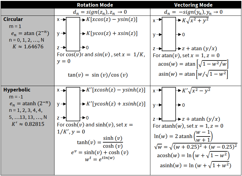
Usage notes:
For solving the respective functions, initialize the CORDIC data (X, Y, and Z) with meaningful initial values within the domain of convergence to ensure result convergence. The ‘useful domain’ listed in the table covers the supported domain of convergence for the CORDIC algorithm and excludes the non-meaningful range(s) for the function
Function limitations must be considered; for example, setting initial X = 0 for atan(Y/X) is not meaningful. Violations of such function limitations may yield incoherent CORDIC result data
All data inputs are processed and handled as two's complements. The only exception is the user-option for X result data (only) to be read as an unsigned value
The only case where the result data is always positive and larger than the initial data is the X result data (only) in the circular vectoring mode; therefore, the user may prefer to use the MSB bit as a data bit instead of a sign bit. By setting X_USIGN = 1, the X result data is processed as unsigned data
For circular and hyperbolic functions, and due to the corresponding fixed LUT, the Z data is always handled as a signed integer Q(1,28), accessible as Q(1,23). The LUTs contain scaled integer values Q(1,28) of atan(2
-n
) for n = 0, 1, 2, ..., 27 and atanh(2
-n
) for n = 1, 2, ..., 27, such that angles in the range [-π,((2
23
-1)/2
23
)π] are represented by integer values ranging [-1,(2
23
-1)/2
23
]. Therefore, Z data is limited (not considering the domain of convergence) to represent angles [-π, ((2
23
-1)/2
23
)π] for these CORDIC functions. Any calculated value of Z outside of this range will result in an overflow error
The MPS setting has no effect on Z data. Ensure proper initialization of Z initial data to prevent overflow and incorrect result data
The CORDIC coprocessor is designed such that, with the correct user setting of MPS > 1, there is no internal overflow of the X and Y data, and the read result data is complete. However, note that in these cases, the higher the MPS setting, the lower the resolution of the result data due to the loss of LSB bit(s)
The hyperbolic rotation mode is limited in terms of result accuracy since the initial Y data must be set to zero. In other words, the CORDIC coprocessor cannot return an accurate result for cosh(Z)+/-sinh(Z) in a single calculation
Domains of convergence
This section does not cover the theory of the inherent limits of CORDIC convergence, which vary with different CORDIC functions in rotation or vectoring mode. For the convergence of result data, there are limitations to the magnitude or value of the initial data and the corresponding useful data form, depending on the operating mode used. The following are generally applicable regarding the convergence of CORDIC result data.
Rotation mode
: Z data must converge towards 0. The initial Z data must be equal to or smaller than Σd
n
· e
n
, where e
n
is always decreasing for iteration n. In other words, |Z| ≤ Sum of LUT. In a circular function, this means the |Z| ≤ integer value represents 1.74 radians. In a hyperbolic function, the |Z| ≤ integer value represents 1.11 radians.
Vectoring mode
: Y data must converge towards 0. The values of initial X and Y are limited by the Z function, which is dependent on the corresponding LUT. In a circular function, |atan(Y/X)| ≤ 1.74 radians. In a hyperbolic function, |atanh(Y/X)| ≤ 1.11 radians. In vectoring mode, the additional requirement is that X > 0.
Circular rotation mode
: The full range of Z input [-2
23
, (2
23
-1)] representing angles [-π, ((2
23
-1)/2
23
)π] is supported. There are no limitations on initial X and Y inputs, except for overflow considerations, which can be overcome with MPS settings.
Circular vectoring mode
: The full range of X and Y inputs [-2
23
,(2
23
-1)] are supported, while the Z initial value should satisfy |Z| ≤ π/2 to prevent possible Z result data overflow.
While the operating modes of the CORDIC coprocessor are generally bound by these convergence limits, there are exceptions for the circular rotation and circular vectoring modes, which use additional pre- and post-processing logic to support a wider range of inputs.
Note:
Considerations should also be given to function limitations, such as the meaning of the result data (for example, dividing by zero is not meaningful). The ‘useful domain’, included within
Figure 35
for each of the main functions, attempts to cover both CORDIC convergence and the useful range of the function.
Note:
Input values may be within the domain of convergence; however, this does not guarantee a fixed level of accuracy of the CORDIC result data.
Overflow considerations
Besides the domain of convergence, consider the limitations on the magnitude of input data to prevent result data overflow.
In all operating modes, the CORDIC coprocessor handles data overflow in the same way. Prevent overflow for X and Y data by setting the MPS bit correctly; the bit's value is partly based on the CORDIC coprocessor operating mode and the application data.
The MPS setting has no effect on the Z data. For circular and hyperbolic functions, any value of Z outside of the range [-π, ((2
23
-1)/2
23
)π] cannot be represented and results in a Z data overflow error. Note that kernel data Z has values in the range [-π, ((2
23
-1)/2
23
)π] scaled to the range [-2
23
, (2
23
-1)], so the written and read values of Z data are always normalized. For a linear function where Z is a real value, the magnitude of Z must not exceed 4 integer bits.
The CORDIC coprocessor accepts (initial) data X, Y, and Z inputs in two's complement format. The result data is also in two's complement format. The only exception is for the X result data in circular vectoring mode. The X result data has a default data format of two's complement, but the user can select via bit CON.X_USIGN = 1 for the X result data to be read as an unsigned value. This option prevents a potential overflow of the X result data (taken together with the MPS setting), as the MSB bit is now a data bit. Note that setting bit CON.X_USIGN = 1 is only effective when operating in the circular vectoring mode, which always yields result data that is positive and larger than the initial data.
Data format
The CORDIC coprocessor accepts initial data (24-bit) X, Y, and Z inputs in two's complement format. The result data (24-bit) is also in two's complement format. The only exception is for the X result data in circular vectoring mode. The X result data has a default data format of two's complement, but the user can select via bit CON.X_USIGN = 1 for the X result data to be read as an unsigned value. This option prevents a potential overflow of the X result data (taken together with the MPS setting), as the MSB bit is now a data bit. Note that setting bit CON.X_USIGN = 1 is only effective when operating in the circular vectoring mode, which always yields result data that is positive and larger than the initial data.
Note:
The X, Y, and Z initial data registers (MXCORDIC_1_0_CORDX, MXCORDIC_1_0_CORDY, and MXCORDIC_1_0_CORDZ) and result data registers (MXCORDIC_1_0_CORRX, MXCORDIC_1_0_CORRY, and MXCORDIC_1_0_CORRZ) all use the bit[31:8] to save data, and bit[7:0] is reserved.
Generally, the input data for X and Y can be an integer or a rational number (fraction). However, in any calculation, the data form must be the same for both X and Y. Also, in the case of fractions, X and Y must have the same number of bits for decimal places. The Z data is always handled as an integer based on the normalization factor for a circular or hyperbolic function.
See the
Normalized result data
section for details on data normalization.
Performance
The CORDIC calculation time increases linearly with increased precision. Increased precision is achieved with a greater number of iterations, which requires an increased width of the data parameters. The CORDIC coprocessor uses barrel shifters for data shifting. For a fixed number of 28 iterations per calculation, the total time from the start of the calculation to the instant the EVFR.CDEOC flag is set is 28/4+3 = 10 kernel clock cycles. Note that the EVFR.CDERR flag is valid only for one kernel clock cycle after the onset of EVFR.CDEOC. This timing for one complete calculation is applicable to those modes that involve additional data processing.
Note:
In hyperbolic modes, the iterations start from n = 1, and the iterations n = 4 and 13 must be repeated to obtain convergence. As a result, a total of n = 27 iterations are executed, except n = 28.
Note:
The above timing excludes the time taken for software loading of initial data and reading of the final result data to and from the six data registers.
Look-up tables
This section describes the look-up tables used in the CORDIC coprocessor kernel. The LUTs are 29 bits wide. Each entry of the atan and atanh LUT is divided into 1 sign bit (MSB), followed by a 28-bit fractional part, Q(1,28).
The Z data is a normalized representation of the actual angle. The internal scaling is such that [-π, ((2
23
-1)/2
23
)π] is equivalent to [-2
28
,(2
28
-1)]. The last 5 LSB bits are truncated, as 24-bit data is transferred to the data bus when addressed. From the user’s point of view, the angles [-π,((2
23
-1)/2
23
)π] are therefore represented by the range [-2
23
,(2
23
-1)].
Iteration No. n | Scaled atan(2 -n ) in hex | Iteration No. n | Scaled atan(2 -n ) in hex |
|---|---|---|---|
0 | 4000000 | 14 | 145F |
1 | 25C80A4 | 15 | A30 |
2 | 13F670B | 16 | 518 |
3 | A2223B | 17 | 28C |
4 | 5161A8 | 18 | 146 |
5 | 28BAFC | 19 | A3 |
6 | 145EC4 | 20 | 51 |
7 | A2F8B | 21 | 29 |
8 | 517CA | 22 | 14 |
9 | 28BE6 | 23 | A |
10 | 145F3 | 24 | 5 |
11 | A2FA | 25 | 3 |
12 | 517D | 26 | 1 |
13 | 28BE | 27 | 1 |
In hyperbolic mode, the iterations n = 4 and n = 13 are repeated, while the iterations n = 0 and n = 27 are skipped. In order to converge at the same number of clock cycles as the circular mode, n = 27 is skipped.
Iteration No. n | Scaled atanh(2 -n ) in hex | Iteration No. n | Scaled atanh(2 -n ) in hex |
|---|---|---|---|
0 | - | 14 | 145F |
1 | 2CC2F12 | 15 | A30 |
2 | 14D01AC | 16 | 518 |
3 | A3D4E0 | 17 | 28C |
4 | 5197FC | 18 | 146 |
5 | 28C1C7 | 19 | A3 |
6 | 145F9D | 20 | 51 |
7 | A2FA6 | 21 | 29 |
8 | 517CE | 22 | 14 |
9 | 28BE6 | 23 | A |
10 | 145F3 | 24 | 5 |
11 | A2FA | 25 | 3 |
12 | 517D | 26 | 1 |
13 | 28BE | 27 | - |
Interrupt generation
The CORDIC interrupt request signal is generated as illustrated in the following diagram:
Figure 36.
CORDIC interrupts generation
Hardware can set the MXCORDIC_1_0_INTR register interrupt flag bits to 1 when the event signal is detected. The MXCORDIC_1_0_INTR.CDEOC is the end of the calculation event flag. The MXCORDIC_1_0_INTR.CDERR is the calculation error event flag. Software can set the MXCORDIC_1_0_INT_SET register interrupt cause bits to 1. The MXCORDIC_1_0_INTR_MASK register can hold the interrupt mask bits of co-located interrupt cause bits in MXCORDIC_1_0_INT; the co-located interrupt cause bit only causes an interrupt when its mask bit is ‘1’. The MXCORDIC_1_0_INTR_MASKED register is a logical AND of the MXCORDIC_1_0_INT_INTR and MXCORDIC_1_0_INTR_MASK registers. The user can read out the interrupt request signal directly via the MXCORDIC_1_0_INTR_MASKED register.
Note:
For the
PSOC™ Control C3
device due to faster calculation by the CORDIC hardware, the use of non-blocking function APIs may not give any speed advantages. It is suggested that the user use the blocking functions directly.
Power, clock, and reset
This section gives an overview of the power supply, clocks, and resets used in this block.
Power supply
CORDIC is available only in active power mode. If the system is in DeepSleep mode, the power domain in which CORDIC is placed is powered down. All flops inside CORDIC are reset without retention. There are no power-related interfaces (P- or Q-channels) in the CORDIC. The CORDIC IP does not implement any internal power domains or power switches.
Clock
CORDIC runs on a single clock input (
clk_sys
). This clock is synchronous to the m33syscpuss clock. The clock can be gated centrally (in MXSPERI) by the SL_CTL.ENABLED MMIO.
Reset
CORDIC has one asynchronous reset signal. The reset can be asserted asynchronously, but it has to be de-asserted synchronously to the system clock. There is no reset synchronization inside this module. The reset synchronization is done inside MXSPERI.
Registers summary
Register | Function |
|---|---|
MXCORDIC_1_0_CTL | module enable/disable register |
MXCORDIC_1_0_ID | module identification register |
MXCORDIC_1_0_INTR | interrupt cause register |
MXCORDIC_1_0_INTR_SET | interrupt set register |
MXCORDIC_1_0_INTR_MASK | interrupt mask register |
MXCORDIC_1_0_INTR_MASKED | Interrupt Masked Register |
MXCORDIC_1_0_KEEP | CORDIC keep register |
MXCORDIC_1_0_CON | CORDIC control register |
MXCORDIC_1_0_CORDX | CORDIC X data register |
MXCORDIC_1_0_CORDY | CORDIC Y data register |
MXCORDIC_1_0_CORDZ | CORDIC Z data register |
MXCORDIC_1_0_CORRX | CORDIC X result register |
MXCORDIC_1_0_CORRY | CORDIC Y result register |
MXCORDIC_1_0_CORRZ | CORDIC Z result register |
MXCORDIC_1_0_STAT | CORDIC status register |
MXCORDIC_1_0_START_CMD | CORDIC start command register |
Program and debug interface
The
PSOC™ Control C3
MCU program and debug interface provides a communication gateway for an external device to perform programming or debugging. The external device can be an Infineon-supplied programmer and debugger, or a third-party device that supports programming and debugging. The serial wire debug (SWD) or the Joint Test Action Group (JTAG) interface can be used as the communication protocol between the external device and the
PSOC™ Control C3
MCU.
Features
The program and debug interface has the following features:
Supports programming and debug through the JTAG or SWD interface
CM33 supports 8-bit Instrumentation Trace Macrocell (ITM) and 4-bit Embedded Trace Macrocell (ETM) tracing
Supports Cross Triggering Interface (CTI) and Cross Triggering Matrix (CTM)
CM33 supports eight hardware breakpoints and four watch-points
Provides read and write access to all memory and registers in the system while debugging, including the CM33 register banks when the core is running or halted
Architecture
shows the block diagram of the program and debug interface in the
PSOC™ Control C3
MCU. The debug and access port (DAP) acts as the program and debug interface. The external programmer or debugger, also known as the “host”, communicates with the DAP of the
PSOC™ Control C3
MCU “target” using either the Serial Wire Debug (SWD) or Joint Test Action Group (JTAG) interfaces. The debug physical port pins communicate with the DAP through the high-speed I/O matrix (HSIOM). See the
I/O subsystem
chapter for details on the HSIOM.
The debug infrastructure is organized in the following groups:
DAP (provides pin interfaces through which the debug host can connect to the target)
Cortex®-M33 core debug components
Other debug infrastructure (includes CTM, the TPIU, and the system ROM table)
Figure 37.
Program and debug architecture
The DAP communicates with the core using the Arm®-specified advanced high-performance bus (AHB) interface. The external host can effectively take control of the entire device through the DAP to perform both programming and debugging operations, the DAP can be disabled in production devices for security.
The following are the various debug and trace components:
Debug components
JTAG and SWD for debug control and access
Trace source components
Trace sink components
Trace port interface unit (TPIU) to drive the trace information out of the chip to an external trace port analyzer
Cross-triggering components
Cross-trigger interface (CTI)
Cross-trigger matrix (CTM)
Debug access port (DAP)
The DAP consists of a combined SWD/JTAG interface (SWJ). The SWJ includes a SWD listener that decides whether the JTAG interface (default after reset) or SWD interface is active. The JTAG and SWD interfaces are mutually exclusive because they share pins.
The debug port (DP) communicates with debug components using the Advanced Peripheral Bus Interconnect (APBIC) infrastructure, which then connects to one of the two AHB Access ports:
The Cortex® -M33 AP connects directly to the AHB debug port and gives access to the Cortex® -M33 internal debug components. This allows access to the rest of the system through the Cortex® -M33 AHB master interface. The AP provides the debug host the same view as an application running on Cortex® -M33. This includes access to the MMIO of other debug components in the Cortex® -M33 subsystem. These debug components can be accessed by the Cortex® -M33 CPU, but cannot be reached through the other APs or by the Cortex® -M33 core.
The System-AP, gives access to the rest of the system, such as user SRAM and Flash, through the AHB mux. This allows access to the System ROM table, which cannot be reached any other way. The system ROM table provides the chip ID, but is otherwise empty.
Both the debug and access port registers are Arm® IPs, which can be found in the Arm® Debug Interface Architecture Specification ADIv6.0.
Note:
The DAP runs asynchronously with the Cortex® M33.
DAP power domain
The entire debugger uses the same power domain as the Cortex® -M33 subsystem. Almost all debug components are part of the Active power domain. The only exception is the SWD as it uses two pins, SWCLKTCK and SWDIOTMS, which are operational in Deep Sleep. This allows for the SWD debug host to connect during Deep Sleep, while the application is running, or while powered down.
After the debugger is connected to the chip, it must bring the chip to the Active state before any operation. For this, the SWD/JTAG-DP has a register (DP_CTL_STAT) with two power request bits: CDBGPWRUPREQ and CSYSPWRUPREQ. These bits request for debug power and system power, respectively. These bits must remain set for the duration of the debug session.
The JTAG pins are only operational in Active mode, which means that the JTAG debug and JTAG boundary scan are not available when the system is in Deep Sleep. JTAG functionality is available only after a chip power-on reset.
Move the chip to the Active state before any operation. When the debugger attaches, it switches the CM33 into the active power domain. All other resources must be turned to an Active state by authenticated or debugging software.
DAP security
The DAP pins are controlled by the policy file. A device from the factory with a standard policy file sets up the DAP pins so that a SWD or JTAG interface can be connected without configuration. When using a secure policy file, configure the DAP pins and enable them in the secure policy file. For more information on the secure policy file, see the
Secured boot
section.
Cortex® -M33 has its own CPUSS_AP_CTL register where the debug features, such as invasive/non-invasive debug and secure privileged invasive/non-invasive debug, can be configured. These debug features are configured in the policy file, which is used by the secure enclave to set the AP_CTL registers in the protected region of Flash. The SYS_AP is controlled by the Cortex® M33 AP_CTL register and is enabled by setting AP_CTL.SYS_DISABLE to ‘00’ in the policy file.
All AP_CTL policy field names that end with _DISABLE are two bits, with ‘00’ being enable, ‘01’ being disable, and ‘1x’ being permanently disabled. For any secure/non-secure debug features to be enabled, AP_CTL.CM33_0_DISABLE must be set to ‘00’.
The following table shows the register configuration in the policy file for Cortex® -M33 for non-secure debugging.
Debug mode | AP_CTL.CM33_0_DBG_DISABLE | AP_CTL.CM33_0_NID_DISABLE |
|---|---|---|
Invasive | 00 | 01 |
Non-Invasive | 01 | 00 |
For secure debug features, set the following in the policy file for Cortex® -M33
Debug mode | AP_CTL.CM33_0_SPID_DISABLE | AP_CTL.CM33_0_SPNID_DISABLE | AP_CTL.CM33_0_SECURE_DISABLE |
|---|---|---|---|
Secure Invasive | 00 | 01 | 00 |
Secure Non-Invasive | 01 | 00 | 00 |
Note:
To enable Secure Invasive Debug, set CM33_0_DBG_DISABLE to ‘00’. To enable Secure Non-Invasive debug, set CM33_0_NID_DISABLE to ‘00’
ROM tables
The CoreSight architecture allows for discoverable debug topology. This means that a debug host can find all debug components available on a chip without knowing the identity of the chip. To discover the chip identity and the debug topology, use the CoreSight ROM tables.
The ROM tables are organized in a tree hierarchy. Each AP has a register that contains a 32-bit address pointing to the base of the root ROM table for that AP. The root ROM table in the debugger is the ‘Dap ROM Table’, which points to the different APs. The Coresight DP component has a register called BASEPTR that points to the DAP ROM table. For
PSOC™ Control C3
MCU there are three such root ROM tables (DAP, M33, and System).
Each ROM table contains 32-bit entries that have an address pointer that either points to the base of the next level ROM table or the base of a leaf debug component. Each ROM table also contains a set of ID registers that hold JEDEC compliant identifiers to identify the manufacturer, part number, and major and minor revision number. For all ROM tables in
PSOC™ Control C3
MCU, these IDs are the same. Each ROM table and CoreSight compliant component also contains component identification registers.
Trace
The Cortex® -M33 include Instrumentation Trace Macrocell (ITM) and Embedded Trace Macrocell (ETM). These components capture the program execution flow from the CPUs and generate trace outputs on the Advanced Trace Bus (ATB). These trace outputs are passed to the core-sight trace funnel (CSTF), which combines multiple trace streams on to a single bus.
Built into the debugger is a 4-bit Trace Port Interface Unit (TPIU). This is used to drive external pins through the IOSS interface, so that the trace can be captured by an external trace port analyzer (TPA). For more information, refer to the Arm® Debug Interface Architecture Specification ADIv6.0.
Embedded cross triggering
Arm® CoreSight includes Embedded Cross Triggering (ECT) that provides the ability to trigger (send or receive) events between different debug components. For example, you can use trigger events to:
Start or stop CPU
Start or stop instruction tracing based on the trace buffer being full, not full, or based on other events
CoreSight uses two main components to support ECT: the Cross-Trigger Interface (CTI) and Cross Trigger Matrix (CTM). The CTI interfaces with other debug components, sending triggers back and forth and synchronizing them as needed. The CTM connects several CTIs, which allows events to be communicated from one CTI to another.
The debug infrastructure provides a CTI that primarily connects events to the TPIU and system triggers.
Note:
The CPU has an internal CTI that connects events between the CPU core and debug components has an internal CTI that connects events between the CPU core and debug components within the CPU (like ETM, DWT etc.). These two CTIs are connected via CTM, which can send/receive events between these two CTIs.
Serial wire debug (SWD) interface
The
PSOC™ Control C3
MCU supports programming and debugging through the SWD interface. The SWD protocol is a packet-based serial transaction protocol. At the pin level, it uses a single bidirectional data signal (SWDIO) and an unidirectional clock signal (SWDCK). The host programmer always drives the clock line, whereas either the host or the target drives the data line. A complete data transfer (one SWD packet) consists of three phases:
Host packet request phase – The host issues a request to the
PSOC™ Control C3
MCU target
Target acknowledge response phase – The
PSOC™ Control C3
MCU target sends an acknowledgement to the host
Data transfer phase – The host or target writes data to the bus, depending on the direction of the transfer
For more information on the SWD implementation, refer to Arm® Debug Interface Architecture Specification ADIv6.0.
JTAG interface
In response to higher pin densities on ICs, the Joint Test Action Group (JTAG) proposed a method to test circuit boards by controlling the pins on the ICs (and reading their values) via a separate test interface. The solution, later formalized as IEEE Standard 1149.1-2001, is based on the concept of a serial shift register routed across all of the pins of the IC – hence the name “boundary scan.” The circuitry at each pin is supplemented with a multipurpose element called a boundary scan cell. In the
PSOC™ Control C3
MCU, most GPIO port pins have a boundary scan cell associated with them (see the GPIO block diagrams in the
I/O subsystem
section). The interface used to control the values in the boundary scan cells is called the Test Access Port (TAP) and is commonly known as the JTAG interface. It consists of three signals: Test Data In (TDI), Test Data Out (TDO), and Test Mode Select (TMS). A clock signal (TCK) that clocks the other signals is also included and a debug TAP reset (TRST) is also present which is an optional input signal. TDI, TMS, and TCK are all inputs to the device and TDO is the output from the device. For more information on the JTAG interface, refer to Arm® Debug Interface Architecture Specification ADIv6.0.
Programming the MCU
The
PSOC™ Control C3
MCU is programmed using the following sequence:
Acquire the SWD port in the
PSOC™ Control C3
MCU
Enter the programming mode
Execute the device programming routines such as Silicon ID Check, Flash Programming, Flash Verification, and Check-sum Verification
SWD port acquisition
When the device is reset by asserting the external reset (XRES) pin, the DP defaults to the JTAG operation. To switch to the SWD protocol, reset the device using XRES to put it into its reset state. The host must send the following SWD connect sequence:
Set SWDIO HIGH for at least five SWCLK cycles. This places the JTAG TAP state machine into the Test Logic Reset state and selects the IDCODE instruction
Change the device from the JTAG to dormant state by writing the 31-bit sequence (0x2EEEEEE6, MSB first) on SWDIO. The device is now in a dormant state
Set SWDIO HIGH for at least eight SWCLK cycles. This ensures that the device is not in the middle of a Selection Alert sequence
On SWDIO, send the 128-bit Selection Alert sequence (0x49CF9046 A9B4A161 97F5BBC7 45703D98, MSB first)
Set SWDIO LOW for four SWCLK cycles
On SWDIO, send the required activation code sequence (0b0101_1000, MSB first)
Place the target into a known state by setting SWDIO HIGH for at least 50 SWCLK cycles. This makes sure the SWD interface is in the line reset state. The device is now in SWD configuration. The
PSOC™ Control C3
MCU uses Dormant operation to move between JTAG to Dormant, and then Dormant to SWD
For more information about this operation, refer to the Arm® Debug Interface Architecture Specification ADIv6.0.
SWD programming mode entry
After the SWD port is acquired, the host must enter the device programming mode within a specific time window. This is done by setting the TEST_MODE bit (bit 31) in the test mode control register (MODE register). Make sure to configure the debug port before entering the device programming mode.
SWD programming routine executions
When the device is in programming mode, the external programmer can start sending the SWD packet sequence for performing programming operations such as flash erase, flash program, checksum verification, and so on.
PSOC™ Control C3
MCU SWD debug interface
The Cortex® -M33 DAP debugging features are classified into two types: invasive debugging and noninvasive debugging. Invasive debugging includes program halting and stepping, breakpoints, and data watch-points. Noninvasive debugging includes instruction address profiling and device memory access, which includes the flash memory, SRAM, and other peripheral registers.
The DAP has three major debug subsystems:
Debug Control and Configuration registers
Breakpoint Unit (BPU) – Provides breakpoint support
Debug Watchpoint (DWT) – Provides watchpoint support
See the Armv8-M architecture reference manual for complete details on the debug architecture.
Note:
The BPU is part of the Flashpoint and Breakpoint (FPB) unit in Arm® Debug Interface Architecture Specification ADIv6.0.
Debug control and configuration registers
The debug control and configuration registers are used to execute firmware debugging. The registers and their key functions are as follows (see the Armv8-M architecture reference manual for the complete bit-level definitions of these registers):
Debug Halting Control and Status Register (DHCSR):
This register contains the control bits to enable debug, halt the CPU, and perform a single-step operation. It also includes status bits for the debug state of the processor.
Debug Fault Status Register (DFSR):
This register describes the reason a debug event occurs and includes debug events, which are caused by a CPU halt, breakpoint event, or watchpoint event.
Debug Core Register Data Register (DCRDR):
This register is used to store the data to write to or read.
Debug Exception and Monitor Control Register (DEMCR):
This register contains the enable bits for global debug watchpoint (DWT) block enable, reset vector catch, and hard fault exception catch.
Break point units (BPU)
The BPU provides breakpoint functionality on instruction fetches. The Cortex® -M33 in the
PSOC™ Control C3
MCU supports four hardware breakpoints. Along with the hardware breakpoints, any number of software breakpoints can be created by using the BKPT instruction. The BPU has the following two types of registers:
The breakpoint control register (FPB_CTRL) is used to enable the BPU and store the number of hardware breakpoints supported by the debug system.
Each hardware breakpoint has a Breakpoint Compare Register (FPB_COMPx). It contains the enable bit for the breakpoint and the compare address value. The typical use case is that when an instruction fetch address matches the compare address of a breakpoint, a breakpoint event is generated and the processor is halted.
Data watchpoints (DWT)
The DWT provides watchpoint support on a data address access or a program counter (PC) instruction address.
The DWT supports two watchpoints for the Cortex® -M33. It also provides an external program counter sampling using a PC sample register, which can be used for noninvasive coarse profiling of the program counter.
The watchpoint compare (DWT_COMPx) registers store the compare values that are used by the watchpoint comparator for the generation of watchpoint events. Each watchpoint has an associated DWT_COMPx register.
The watchpoint function (DWT_FUNCTIONx) registers store the conditions that trigger the watchpoint events. They may be program counter watchpoint event or data address read/write access watchpoint events. A status bit is also set when the associated watchpoint event occurs.
The watchpoint comparator PC sample register (DWT_PCSR) stores the current value of the program counter. This register is used for coarse, non-invasive profiling of the program counter register.
Debugging the
PSOC™ Control C3
device
The host debugs the target by accessing the debug control and configuration registers, BPU registers, and DWT registers. All registers are accessed through the SWD interface; in the Cortex® -M33, DAP converts the SWD packets to appropriate register access through the DAP-AHB interface.
The first step in debugging the target is to acquire the SWD port. The acquire sequence can be found in the SWD port acquisition section. The SWD port is acquired when the correct Cortex® -M33 DAP SWDID is read from the target device. For the debug transactions to occur on the SWD interface, do not use the corresponding pins for any other purpose. See the
I/O subsystem
section to understand how to configure the SWD port pins, allowing them to be used only for the SWD interface or for other functions such as LCD and GPIO. If debugging is required, do not use the SWD port pins for other purposes.
If only programming support is needed, the SWD pins can be used for other purposes. When the SWD port is acquired, the external debugger sets the C_DEBUGEN bit in the DHCSR register to enable debugging. Then, the different debugging operations such as stepping, halting, breakpoint configuration, and watchpoint configuration are carried out by writing to the appropriate registers in the debug system.
Registers summary
Name | Description |
|---|---|
CPUSS_AP_CTL | Configure debug features |
Cryptographic accelerator
The cryptographic accelerator block provides hardware implementation and acceleration of cryptographic functions. Implementation in hardware takes less time and energy than the equivalent firmware implementation. In addition, the block provides True Random Number Generation (TRNG) functionality. The
PSOC™ Control C3
MCU cryptographic accelerator block name is CryptoLite.
Features
The following are the features of the cryptographic accelerator:
Advanced Encryption Standard (AES)-128 to accelerate block cipher functionality and only supports the encryption functionality of a single 128-bit block with a fixed 128-bit key
Secure Hash Algorithm (SHA)-256 to accelerate hash functionality
True random number generator (TRNG)
Vector unit (VU) to support asymmetric key cryptography, such as RSA and Elliptic-Curve Cryptography (ECC)
Architecture
The following figure gives an overview of the CryptoLite block.
Figure 38.
CryptoLite block diagram
The CryptoLite block has the following interfaces:
AHB slave interface: External bus masters use this interface to access the block MMIO registers
AHB master interface: The block uses this interface to access hardware function data structures and operands in memories (FLASH and SRAM)
Two interrupts: One interrupt for regular behavior, for example, TRNG is initialized. One interrupt for irregular/erroneous behavior, for example, when the AHB master interface encounters a bus error
Randomized clock: This is the TRNG digitized analog signal (DAS) bit-stream sequence
A clock and reset signal interface connects to the System Resources subsystem (SRSS)
The CryptoLite block provides hardware acceleration for a minimal set of cryptographic functions. The functionality is implemented by four components:
AES-128 component: To accelerate block cipher functionality. The component supports:
Forward encryption of a single 128-bit block with a 128-bit key
SHA-256 component: To accelerate hash functionality. The component supports:
Message schedule calculation for a 512-bit message chunk
Processing of a 512-bit message chunk
Vector unit (VU) component: To accelerate asymmetric key cryptography (for example, RSA and ECC). The component supports:
Large integer multiplication, addition, and so on
TRNG component: Based on a set of ring oscillators, the TRNG includes a hardware health monitor. This component generates true random numbers using up to six ring oscillators
The component provides speeds up, for example, secure boot Digital Signature Authentication (DSA or ECDSA) through its SHA-256 and VU hardware acceleration. The digital signature provides message authentication, integrity, and non-repudiation.
Randomized clock
The CryptoLite exposes the TRNG digitized analog signal (DAS) bit-stream sequence at its interface signal “
tr_trng_bitstream
”. The sequence may be used to randomize the timing of functionality. This signal can be routed to GPIOs and DMA using the trigger multiplexer. See the
Trigger multiplexer (Trigger MUX)
chapter for more details.
The default value of the “
tr_trng_bitstream
” signal is set to constant ‘0’ when oscillators are not enabled.
The TRNG functionality may be stopped by the monitor on repetition count (RC) or adaptive proportion (AP) error detection. If the TRNG functionality is stopped, both the DAS bit-stream and the randomized clock signal are set to constant ‘0’. If the “stop functionality” is not enabled, the DAS bit-stream and the randomized clock will continue to produce random bit sequences. See the
True random number generator (TRNG)
section for more details.
Hardware/Software interface
The SHA-256, AES-128, and VU components have a similar hardware/software interface. The following components have a dedicated MMIO register that provides a pointer to a data structure in memory:
The SHA-256 component uses the CRYPTOLITE_SHA_DESCR pointer register
The AES-128 component uses the CRYPTOLITE_AES_DESCR pointer register
The VU component uses the CRYPTOLITE_VU_DESCR pointer register
A write to one of these MMIO registers starts a hardware function. The block will read the data structure from memory, and the data structure specifies the desired hardware function and its operands. The data structures are hardware-function-specific. The block performs the specified hardware function. From start to finish, the hardware function is considered busy.
While a hardware function (SHA-256, AES-128, VU) is busy, the CryptoLite block cannot accept a new MMIO register write transfer; a new MMIO register write transfer will be made pending, which blocks any other (write or read) MMIO register transfers
While a hardware function is busy and the CryptoLite block is not blocked, the block can accept a new MMIO register read transfer. For example, a read transfer may read the CRYPTOLITE_STATUS register, which indicates if the CryptoLite block is busy
The above behavior has the following implications:
Only one hardware function (SHA-256, AES-128, VU) can be busy/active at the same time; that is, they are mutually exclusive. This is desired as the implementation shares hardware resources
The data structure pointer MMIO registers cannot be overwritten by software while a hardware function is busy
Software may prepare a next data structure in memory and write its pointer to a data structure pointer MMIO register while a hardware function is not busy. The write transfer of the next data structure's pointer will block the cryptographic block. This prevents the data structure pointer MMIO register from being overwritten
Note:
Software should ensure that the current (busy) and next data structures in memory do not overlap
Note:
The TRNG and a hardware function (SHA-256, AES-128, VU) can be active at the same time. However, a TRNG MMIO register write transfer will be made pending when a hardware function is busy. Therefore, it is advised that the TRNG functionality be setup/started before the hardware functions are used. A TRNG MMIO register read transfer (CRYPTOLITE_INTR_TRNG and CRYPTOLITE_TRNG_RESULT) is possible when a hardware function is busy.
As mentioned, a data structure in memory specifies the hardware function and its operands. The operands are typically pointers to 8-bit bytes or 32-bit word sequences in memory. These sequences in memory may represent a secret key (AES-128), a message chunk (SHA-256), or a long unsigned integer number (VU).
Figure 39
shows a high-level block diagram of the descriptor, data structure, and operands.
Figure 39.
CryptoLite hardware/software interface
Most cryptographic functions are implemented using a combination of CPU software and hardware acceleration.
A hardware function (SHA-256, AES-128, VU) uses an AHB master interface to access memory. A bus error is reported (CRYPTOLITE_INTR_ERROR.BUS_ERROR), and the hardware function is terminated under an AHB bus error.
Block functions
AES-128
The AES-128 block cipher function is a member of the AES block cipher family. It encrypts a 128-bit block with a 128-bit key.
A block cipher mode of operation uses the AES-128 block cipher function in a specific configuration to provide message confidentiality and authenticity. The CryptoLite component provides AES-128 block cipher function hardware acceleration. A specific block cipher mode of operation is implemented using software and hardware acceleration. Typically, a message is broken up into multiple 128-bit blocks. The common modes of operation are:
Electronic Code Book (ECB)
Cipher Block Chaining (CBC)
Cipher Feedback (CFB)
Output Feedback (OFB)
Counter (CTR)
The AES-128 block cipher function performs 10 rounds. Each round updates the internal cipher state. Each round has a dedicated 128-bit round key, which is derived from the provided 128-bit key.
The CryptoLite AES-128 block cipher function hardware acceleration consists of a single hardware function:
Encrypt
: Encrypt a 128-bit block P (plain-text) with a 128-bit SK (secret key) into a 128-bit block C (cipher-text)
A write to the CryptoLite block's CRYPTOLITE_AES_DESCR MMIO register starts a 128-bit AES encryption in the ECB mode. The CRYPTOLITE_AES_DESCR register expects a pointer to a three 32-bit word structure in memory. The pointer must be 32-bit word-aligned. The CryptoLite component retrieves the three control words that specify the hardware function.
Word 0
: Pointer to a 16 * 8-bit secret key SK. The secret key is a hardware function input
Word 1
: Pointer to a 16 * 8-bit block P. The block is a hardware function input
Word 2
: Pointer to a 16 * 8-bit block C. The block is a hardware function output
The following figure shows AES-128 data flow.
Figure 40.
AES-128 data flow
Note:
The AES-128 block cipher function operates on 8-bit bytes. As a result, no special endianness considerations are applicable from a hardware point of view.
SHA-256
The SHA-256 hash function is a member of the SHA-2 hash family. To calculate a message's hash value (also known as message digest), a message is broken up into multiple 512-bit message chunks. The SHA-256 hash function processes a single message chunk.
The SHA-256 hash function has an internal 256-bit (eight 32-bit words) hash state H[j] (with j = 0, …, 7). For the first message chunk, the start hash state is initialized with SHA-256 pre-defined values. For each successive message chunk, the start hash state is the previous message chunk's end hash state. The final message chunk's end hash state is the message's hash value.
The SHA-256 hash function performs 64 rounds of a compression function. Each compression function round updates the internal hash state. Each round has a dedicated 32-bit round constant K[i] and a dedicated 32-bit message schedule value W[i].
The round constants have SHA-256 pre-defined values; they are fixed.
The message schedule values are created from the 512-bit message chunk; they are message-specific.
The CryptoLite SHA-256 hash function hardware acceleration consists of two hardware functions:
Message schedule function: Creation of 64 * 32-bit message schedule values W[i] (with = 0, …, 63) from a 512-bit message chunk M
Process function: SHA-256 processing of a 256-bit hash state by performing 64 rounds of a compression function. The process inputs are a 256-bit hash state and a message schedule W (as created by the message schedule function). The process output is an updated 256-bit hash state. Note that the round constants K are an implicit rather than explicit process input (they are hardwired in the process function)
To process a single message chunk, one message schedule hardware function is performed, followed by one process hardware function.
A write to the CRYPTOLITE_SHA_DESCR MMIO register starts a hardware function. The CRYPTOLITE_SHA_DESCR register expects a pointer to a three 32-bit word structure in memory.
Note:
The pointer must be 32-bit word-aligned.
The CryptoLite component retrieves the three control words that specify the hardware function. The first word (word 0) is generic; the other two words (words 1 and 2) are hardware function-specific.
Word 0
bit position 28 is used to specify the hardware function
If WORD0[28] is '0', a message schedule hardware function is performed
If WORD0[28] is '1', a process hardware function is performed
For a message schedule function, words 1 and 2 are defined as follows:
Word 1
: Pointer to a 16 * 32-bit (512 bit) message chunk M. The message chunk is a hardware function input. The pointer must be 32-bit word-aligned
Word 2
: Pointer to a 64 * 32-bit (2048 bit) message schedule array W. The message schedule is a hardware function output. The pointer must be 32-bit word-aligned
For a process function, words 1 and 2 are defined as follows:
Word 1
: Pointer to an 8 * 32-bit (256 bit) hash state H. The hash state is both a hardware function input and a hardware function output (the input is overwritten by the output). The pointer must be 32-bit word-aligned
Word 2
: Pointer to a 64 * 32-bit (2048 bit) message schedule array W. The message schedule is a hardware function input. The pointer must be 32-bit word-aligned
Note:
The SHA-256 hash function operates on 32-bit words and assumes a big-endian memory layout of these words in memory. The
PSOC™ Control C3
MCU uses a little-endian memory layout. This has the following implications:
When a message chunk's 8-bit bytes are used to construct the message schedule's 32-bit words W[i], a little-to-big-endian conversion ("LE2BE") is processed by hardware
When a final hash value's 32-bit words H[j] are used as a message digest (assuming the message digest is considered a byte stream), a big-to-little-endian conversion ("BE2LE") is required by software
Vector unit (VU)
The vector unit (VU) supports long integer operations that are useful for asymmetric key cryptography such as RSA or Elliptic-curve cryptography (ECC).
The operations have a single destination operand (DST) and one or two source operands (SRC0 and SRC1). Each operand has a specific bit size. This bit size is specified in 32-bit word multiples. A value of x specifies a bit size of (x+1) * 32 bits.
The VU supports the following long integer operations:
MUL: This operation is a regular long integer multiplication operation.
DST[dst_bit_size-1:0] = SRC0[src0_bit_size-1:0] * SRC1[src1_bit_size-1:0]
XMUL: This operation is a carry-less long integer multiplication operation.
DST[dst_bit_size-1:0] = SRC0[src0_bit_size-1:0] xmul SRC1[src1_bit_size-1:0]
ADD: This operation is a long integer addition operation.
DST[dst_bit_size-1:0] = SRC0[src0_bit_size-1:0] + SRC1[src1_bit_size-1:0]
SUB: This operation is a long integer subtraction operation.
DST[dst_bit_size-1:0] = SRC0[src0_bit_size-1:0] - SRC1[src1_bit_size-1:0]
XOR: operation. This operation is a long integer exclusive-or operation.
DST[dst_bit_size-1:0] = SRC0[src0_bit_size-1:0] ^ SRC1[src1_bit_size-1:0]
MOV: This operation moves/copies a long integer.
DST[dst_bit_size-1:0] = SRC0[src0_bit_size-1:0]
LSR1: This operation shifts a long integer 1-bit position to the right.
DST[dst_bit_size-1:0] = SRC0[src0_bit_size-1:0] >> 1
LSL1: This operation shifts a long integer 1-bit position to the left.
DST[dst_bit_size-1:0] = SRC0[src0_bit_size-1:0] << 1
LSR: This operation shifts a long integer a specific number of bit positions to the right.
DST[dst_bit_size-1:0] = SRC0[src0_bit_size-1:0] >> “bit shift amount”
COND_SUB: This operation is a conditional long integer subtraction operation.
DST[dst_bit_size-1:0] = (SRC0[src0_bit_size-1:0] >= SRC1[src1_bit_size-1:0]) ? (SRC0[src0_bit_size-1:0] - SRC1[src1_bit_size-1:0]) : SRC0[src0_bit_size-1:0]
Note:
The operation’s “greater than equal” operator uses the source bit size (not the destination bit size), and the operation’s “subtraction” operator uses the destination bit size
A write to the CRYPTOLITE_VU_DESCR register starts a VU operation. The CRYPTOLITE_VU_DESCR register expects a pointer to a four 32-bit word structure in memory. The pointer must be 32-bit word-aligned. The CryptoLite component retrieves the four control words that specify the hardware function. The first word (word 0) is generic; the other three words (words 1, 2, and 3) are hardware function-specific.
Word 0
:
Bit positions 31:28 specify the operation
Table 90.
Vector unit opcodes
Opcode
Operation
0
Multiplication (MUL)
1
Addition (ADD)
2
Subtraction (SUB)
3
Exclusive or (XOR)
4
Binary multiplication (XMUL)
5
Logical shift right by 1 (LSR1)
6
Logical shift left by 1 (LSL1)
7
Logical shift right (LSR)
8
Conditional subtraction (COND_SUB)
9
Move (MOV)
a
to
f
Reserved
Bit positions 27:25 are reserved
Bit positions 24:16 specify the word length (minus 1) of the destination operand. A 9-bit word length allows for up to 512 32-bit word (16384-bit) destination operands
Bit positions 15:8 specify the word length (minus 1) of source operand 1 (if present)
Bit positions 7: 0 specify the word length (minus 1) of source operand 0 (if present). An 8-bit word length allows for up to 256 32-bit word (8192-bit) source operands
Note:
Note that for reserved opcodes (>9), there is no change in hardware state and only a few cycles STATUS.BUSY will be high. This is because CryptoLite hardware does not know if the VU opcode is undefined at the point of start initiated by MMIO write, so CryptoLite will be busy until it fetches the opcode from the descriptor location and becomes idle (STATUS.BUSY is cleared to ‘0’ when an undefined opcode is detected)
For MUL, XMUL, ADD, SUB, XOR, and COND_SUB operations, words 1, 2, and 3 are defined as follows:
Word 1
: Pointer to word 0 (the least significant word) of source operand 0. The pointer must be 32-bit word-aligned
Word 2
: Pointer to word 0 (the least significant word) of source operand 1. The pointer must be 32-bit word-aligned
Word 3
: Pointer to word 0 (the least significant word) of the destination operand. The pointer must be 32-bit word-aligned
For LSR1, LSL1, and MOV operations, words 1, 2, and 3 are defined as follows:
Word 1
: Pointer to word 0 (the least significant word) of the source operand. The pointer must be 32-bit word-aligned
Word 2
: Not used
Word 3
: Pointer to word 0 (the least significant word) of the destination operand. The pointer must be 32-bit word-aligned
For LSR operations, words 1, 2, and 3 are defined as follows:
Word 1
: Pointer to word 0 (the least significant word) of the source operand. The pointer must be 32-bit word-aligned
Word 2
: Shift amount. Bit positions 12:0 specify the shift amount
Word 3
: Pointer to word 0 (the least significant word) of the destination operand. The pointer must be 32-bit word-aligned
Note on operand size:
The source and destination operands have dedicated size specifications. The destination operand may be larger than the source operands. Typically, this is useful for multiplication operations
When a destination operand size is smaller than the operation result size, the more significant bits of the operation result are ignored. When a destination operand size is larger than the operation result size, the operation result ‘0’ is extended
Typically, the source operand and destination operand occupy different memory locations. However, to limit memory allocation, it may be beneficial to:
Use the same memory locations for the two source operands. This can be done without any restrictions. For example, the two source operands of an ADD operation are the same to double the source operand
Use the same memory locations for the source and the destination operands. This comes with restrictions that are operation dependent. Specifically, the following operations allow for the use of the same memory locations for the source operand and the destination operand:
ADD, SUB, XOR, MOV, LSR1, and LSL1 operations
The following operations do not allow for the use of the same memory locations for the source and the destination operands:
MUL, XMUL, LSR, and COND_SUB operations
Note:
The VU operates on 32-bit word multiples and assumes a little-endian memory layout of these words in memory. The
PSOC™ Control C3
MCU uses a little-endian memory layout. As a result, no endianness conversion is required.
True random number generator (TRNG)
The true random number generator component (TRNG) generates true random numbers. The bit size of these generated numbers is fixed at 32 bits.
The TRNG relies on up to six ring oscillators to provide physical noise sources. A ring oscillator consists of a series of inverters connected in a feedback loop to form a ring. Due to the temperature sensitivity of the inverter delays, jitter is introduced to a ring's oscillating signal. The jittered oscillating signal is sampled to produce a "digitized analog signal" (DAS). This is done for all multiple-ring oscillators.
To increase entropy and reduce bias in DAS bits, the DAS bits are further post-processed. Post-processing involves two steps:
An optional reduction step (over up to six ring oscillator DAS bits and over one or multiple DAS bit periods) to increase entropy
An optional “von Neumann correction” step to reduce a ‘0’ or ‘1’ bias
This correction step processes pairs of reduction bits as produced by the previous step. Given two reduced bits r0 and r1 (with r0 being produced before r1), the correction step is defined as follows:
(r0, r1) = (0, 0): no bit is produced
(r0, r1) = (0, 1): a ‘0’ bit is produced (bit r0)
(r0, r1) = (1, 0): a ‘1’ bit is produced (bit r0)
(r0, r1) = (1, 1): no bit is produced
That is, the correction step only produces a bit on a ‘0’ to ‘1’ or ‘1’ to ‘0’ transition. Note that for a random input bit sequence, the correction step produces an output bit sequence of close to one-quarter the frequency of the input bit sequence (the input reduction bits are processed in non-overlapping pairs, and only half of the pair encodings result in an output bit).
Post-processing produces bit samples that are considered true random bit samples. The true random bit samples are shifted into a register to provide random values of up to 32 bits.
As a result of high switching activity, ring oscillators consume a significant amount of power. Therefore, when the TRNG functionality is disabled, the ring is "broken" to prevent switching. When TRNG functionality is enabled, a ring oscillator initially has predictable behavior. However, over time, infinitesimal environmental (temperature) changes cause an increasing deviation from this predictable behavior.
During the initial delay, the ring oscillator is not a reliable physical noise source
After an initial delay, the same ring oscillator will show different oscillation behavior and provide a reliable physical noise source
Therefore, the DAS bits can be dropped during an initialization period (CRYPTOLITE_TRNG_CTL0.INIT_DELAY).
The following figure gives an overview of the TRNG component.
Figure 41.
TRNG overview
The FEEDBACK_EN bitfield of the CRYPTOLITE_TRNG_CTL0 register controls the feedback. When ‘0’, there is no feedback. This functionality is present, as it was found that the “von Neumann” corrector may be less effective with feedback enabled.
The “Sampler” logic digitizes an oscillating signal. The following figure illustrates the functionality.
Figure 42.
Sampler logic
Note:
When a ring oscillator is disabled, the synchronization logic is reset. Therefore, the ring oscillator contributes a constant ‘0’ to the reduction step of the post-processing.
As mentioned, the TRNG relies on up to six ring oscillators:
RO11: A fixed-ring oscillator consisting of 11 inverters
RO15: A fixed-ring oscillator consisting of 15 inverters
GARO15: A fixed Galois-based ring oscillator of 15 inverters
GARO31: A flexible Galois-based ring oscillator of up to 31 inverters. A programmable polynomial of up to order 31 provides flexibility in the oscillator feedback
FIRO15: A fixed Fibonacci-based ring oscillator of 15 inverters
FIRO31: A flexible Fibonacci-based ring oscillator of up to 31 inverters. A programmable polynomial of up to order 31 provides flexibility in the oscillator feedback
Each ring oscillator can be enabled or disabled. When disabled, the ring is “broken” to prevent switching. The XXX_EN enable signals originate from the CRYPTOLITE_TRNG_CTL1 register.
Fixed ring oscillators: RO11, RO15, GARO15, FIRO15
The following figure illustrates the schematics of the fixed-ring oscillators.
Figure 43.
Four fixed-ring oscillators: RO11, RO15, GARO15, and FIRO15
Ring oscillator: GARO31
The flexible Galois based-ring oscillators rely on programmable polynomials to specify the oscillator feedback. This allows for rings of 1, 3, 5,…, 31 inverters (an odd number is required to generate an oscillating signal). The following figure gives an overview of the Galois-based ring oscillator.
Figure 44.
Flexible Galois-based ring oscillator: GARO31
When the ring oscillator is disabled (GARO31_EN bit of the CRYPTOLITE_TRNG_CTL1 register is ‘0’), the polynomial is forced to “0” and the ring is broken, as illustrated in the following figure.
Figure 45.
GARO31 stopped
The programmable polynomial specifies the oscillator feedback. The following figure illustrates two examples.
Figure 46.
GARO31 examples
Ring oscillator: FIRO31
The flexible Fibonacci-based ring oscillators rely on programmable polynomials to specify the oscillator feedback. This allows for rings of 1, 3, 5,…, 31 inverters (an odd number is required to generate an oscillating signal). The following figure gives an overview of the Fibonacci-based ring oscillator.
Figure 47.
Flexible Fibonacci-based ring oscillator: FIRO31
When the ring oscillator is disabled (FIRO31_EN bit of the CRYPTOLITE_TRNG_CTL1 register is ‘0’), the polynomial is forced to “0” and the ring is broken, as illustrated in the following figure.
Figure 48.
FIRO31 stopped
The programmable polynomial specifies the oscillator feedback. The following figure illustrates two examples.
Figure 49.
FIRO31 examples
TRNG result
A 32-bit TRNG value is provided through a read from the CRYPTOLITE_TRNG_RESULT register. This read is a blocking read; when 32-bit is not available, the read is blocked. A read from the CRYPTOLITE_TRNG_RESULT register returns “0” when the TRNG is not enabled (all XXX_EN fields of the CRYPTOLITE_TRNG_CTL1 register are ‘0’).
TRNG health monitor
The TRNG has a built-in health monitor that performs tests on the digitized noise source to detect deviations from the intended behavior. For example, the health monitor detects “stuck at” faults in the digitized analog samples. The following figure illustrates the functionality of the health monitor.
Figure 50.
TRNG health monitor
The health monitor tests one out of three selected digitized bit streams:
DAS bit-stream: This is the XOR of the digitized analog samples
RED bit-stream: This is the bit-stream of reduction bits. Note that each reduction bit may be calculated over multiple DAS bits
TR bit-stream: This is the bit-stream of true random bits (after the “von Neumann reduction” step)
The health monitor performs two different tests:
The repetition count test
This test checks for the repetition of the same bit value (‘0’ or ‘1’) in a bit-stream. A detection indicates that a specific active bit value (specified by a status field BIT) has repeated for a pre-programmed number of bits (specified by a control field CUTOFF_COUNT8[7:0] of the CRYPTOLITE_RNG_MON_RC_CTL register). The test uses a counter to maintain the number of repetitions of the active bit value (specified by the status field REP_COUNT[7:0] of the CRYPTOLITE_TRNG_MON_RC_STATUS1 register).
If the test is started (specified by the RC bitfield of the CRYPTOLITE_TRNG_MON_CTL register) and a change in the bit-stream value is observed, the active bit value BIT is set to the new bit value, and the repetition counter REP_COUNT[] is set to “1”. If the bit-stream value is unchanged, the repetition counter REP_COUNT[] is incremented by “1”.
A detection stops the repetition count test (hardware sets the RC bit of the CRYPTOLITE_TRNG_MON_CTL register to ‘0’), sets the associated interrupt status field to ‘1’, and ensures that hardware does not modify the status fields. When the test is stopped, REP_COUNT[] equals CUTOFF_COUNT8[].
A detection stops the TRNG functionality (all XXX_EN fields of the CRYPTOLITE_TRNG_CTL1 register are set to ‘0’ by hardware) if the STOP_ON_RC_DETECT bit of the CRYPTOLITE_TRNG_CTL0 register is set to ‘1’
The adaptive proportion test
This test checks for a disproportionate occurrence of a specific bit value (‘0’ or ‘1’) in a bit stream. A detection indicates that a specific active bit value (specified by a status field BIT) has occurred a pre-programmed number of times (specified by a control field CUTOFF_COUNT16[15:0] of the CRYPTOLITE_TRNG_MON_AP_CTL register) in a bit sequence of a specific bit window size (specified by a control field WINDOW_SIZE31:16 of CRYPTOLITE_TRNG_MON_AP_CTL register). The test uses a counter to maintain an index in the current window (specified by WINDOW_INDEX[15:0] of the CRYPTOLITE_TRNG_MON_AP_STATUS1 register) and a counter to maintain the number of occurrences of the active bit value (specified by the status field OCC_COUNT31:16 of the CRYPTOLITE_TRNG_MON_AP_STATUS1 register).
If the test is started (specified by the AP bit of the CRYPTOLITE_TRNG_MON_CTL register), the bit-stream is partitioned into bit sequences of a specific window size. At the first bit of a bit sequence, the active bit value BIT is set to the first bit value, the counter WINDOW_INDEX is set to “0”, and the counter OCC_COUNT is set to “1”. For all other bits of a bit sequence, the counter WINDOW_INDEX is incremented by “1”. If the new bit value equals the active bit value BIT, the counter OCC_COUNT[] is incremented by “1”. Note that the active bit value BIT is only set at the first bit of a bit sequence.
A detection stops the adaptive proportion test (hardware sets the AP bit of the CRYPTOLITE_TRNG_MON_CTL register to ‘0’), sets the associated interrupt status field to ‘1’, and ensures that hardware does not modify the status fields. When the test is stopped, OCC_COUNT[] equals CUTOFF_COUNT16[] and the WINDOW_INDEX identifies the bit sequence index on which the detection occurred.
A detection stops the TRNG functionality (all XXX_EN fields of the CRYPTOLITE_TRNG_CTL1 register are set to ‘0’ by hardware) if the STOP_ON_AP_DETECT bit of the CRYPTOLITE_TRNG_CTL0 register is set to ‘1’
Interrupts
The CryptoLite provides two interrupts:
TRNG interrupt
Error interrupt
TRNG interrupt
This interrupt is used to report TRNG behavior, and this interrupt is generated for the below scenarios:
TRNG is initialized
TRNG data is available in the CRYPTOLITE_TRNG_RESULT register
TRNG monitor detects a "repetition count" error
TRNG monitor detects an "adaptive proportion" error
The TRNG interrupt has an interrupt mask in the CRYPTOLITE_INTR_TRNG_MASK register. By making the interrupt mask low, the corresponding interrupt source is ignored. The TRNG interrupt is generated if the interrupt mask bit is high and the corresponding interrupt source is pending.
When servicing a TRNG interrupt, the interrupt service routine (ISR) can clear the interrupt source by writing a ‘1’ to the corresponding interrupt bit in the CRYPTOLITE_INTR_TRNG register.
The CRYPTOLITE_INTR_TRNG_MASKED register is the logical AND between the interrupt sources and the interrupt mask. This register provides a convenient way for the firmware to determine the source of the interrupt.
For verification and debug purposes, a set bit (such as DATA_AVAILABLE in the CRYPTOLITE_INTR_TRNG_SET register) is used to trigger each interrupt. This action allows the firmware to generate an interrupt without the actual event occurring.
Error interrupt
This interrupt is generated for an AHB bus error on the AHB master interface.
The error interrupt is enabled by setting the BUS_ERROR bit of the CRYPTOLITE_INTER_ERROR_MASK register and reads the CRYPTOLITE_INTR_ERROR_MASKED register to know the interrupt masked status forwarded to the CPU interrupt controller.
When servicing the error interrupt, the interrupt service routine (ISR) can clear the interrupt by writing a "1" to the BUS_ERROR bit of the CRYPTOLITE_INTR_ERROR register.
The BUS_ERROR bit of the CRYPTOLITE_INTR_ERROR_SET register can be used to assert an interrupt for firmware debugging.
Note:
The cryptographic block terminates its AES, SHA, or VU functionality when it detects an error. The error is sticky; this allows software to check for an error after a series of operations rather than checking after every individual operation.
Registers summary
Register | Function |
|---|---|
CRYPTOLITE_CTL | CryptoLite control register |
CRYPTOLITE_STATUS | CryptoLite status register |
CRYPTOLITE_AES_DESCR | AES descriptor pointer register |
CRYPTOLITE_VU_DESCR | VU descriptor pointer register |
CRYPTOLITE_SHA_DESCR | SHA descriptor pointer register |
CRYPTOLITE_INTR_ERROR | CryptoLite error interrupt register |
CRYPTOLITE_INTR_ERROR_SET | CryptoLite error interrupt set register |
CRYPTOLITE_INTR_ERROR_MASK | CryptoLite error interrupt mask register |
CRYPTOLITE_INTR_ERROR_MASKED | CryptoLite masked error interrupt output register |
CRYPTOLITE_TRNG_CTL0 | TRNG control 0 register |
CRYPTOLITE_TRNG_CTL1 | TRNG control 1 register |
CRYPTOLITE_TRNG_STATUS | TRNG status register |
CRYPTOLITE_TRNG_RESULT | TRNG result register |
CRYPTOLITE_TRNG_GARO_CTL | TRNG Galois-based ring oscillator (GARO) control register |
CRYPTOLITE_TRNG_FIRO_CTL | TRNG Fibonacci-based ring oscillator (FIRO) control register |
CRYPTOLITE_TRNG_MON_CTL | TRNG health monitor control register |
CRYPTOLITE_TRNG_MON_RC_CTL | TRNG health monitor repetition count test control register |
CRYPTOLITE_TRNG_MON_RC_STATUS0 | TRNG health monitor repetition count test status 0 register |
CRYPTOLITE_TRNG_MON_RC_STATUS1 | TRNG health monitor repetition count test status 1 register |
CRYPTOLITE_TRNG_MON_AP_CTL | TRNG health monitor adaptive proportion test control register |
CRYPTOLITE_TRNG_MON_AP_STATUS0 | TRNG health monitor adaptive proportion test status 0 register |
CRYPTOLITE_TRNG_MON_AP_STATUS1 | TRNG health monitor adaptive proportion test status 0 register |
CRYPTOLITE_INTR_TRNG | TRNG interrupt register |
CRYPTOLITE_INTR_TRNG_SET | TRNG interrupt set register |
CRYPTOLITE_INTR_TRNG_MASK | TRNG interrupt request mask register |
CRYPTOLITE_INTR_TRNG_MASKED | TRNG masked interrupt output register |
TrustZone
Features
Arm® TrustZone enabled Cortex®-M33 CPU
Secure and non-secure CPU states
Attribution units - Secure Attribution Unit (SAU) and Implementation Defined Attribution Unit (IDAU)
Secure and non-secure aliasing of the memory map
Secure and non-secure interrupts
Secure and non-secure peripherals
Secure and non-secure debug
Architecture
Arm® TrustZone technology is an optional security extension designed for Armv8-M. The security extension is enabled on
PSOC™ Control C3
devices for improved security.
TrustZone implements system-wide security by partitioning the resources (memory and peripherals) into secure or non-secure worlds. TrustZone introduces two more states to the CPU - secure and Non-secure. These security states are orthogonal to the existing Thread and Handler modes, resulting in four modes: Secure Handler, Secure Thread, Non-secure Handler, and Non-secure Thread modes. In the
PSOC™ Control C3
device, with TrustZone extension enabled, the M33 CPU starts in a secure state. In the secure state the software has access to both secure as well as non-secure resources, while in the non-secure state, software has access only to non-secure resources. This allows execution of secure and non-secure software on the same CPU with an isolation of resources between the two worlds and which is based on the memory map. The partitioning of memory map is achieved with a programmable Secure Attribution Unit (SAU) and a fixed Implementation Defined Attribution Unit (IDAU).
Figure 51.
Arm® TrustZone enabled system overview
The following key internal resources are banked between secure and non-secure states:
Stack pointers
Interrupt Masking registers
MPU
SysTick timer
VTOR
Some other registers of System Control Block
Some registers are banked on a bit-by-bit basis. The M33 CPU has separate vector tables for secure and non-secure software. With the security extension enabled, a new SecureFault exception is added in the system.
Memory regions
The complete 4 GB address space is partitioned into secure and non-secure regions. These regions are aliased in the address space, meaning that one memory location is mapped to two different locations in the address map, one in the secure region and the other in the non-secure region. All memories and peripherals are aliased and placed in both regions.
The address space is partitioned into three regions:
Secure (S):
Secure addresses are used for accessing memory and peripherals which are accessible only by Secure software
A CPU in secure state can only execute instructions from the secure region
Data in secure addresses is accessible by Secure software
Non-secure callable (NSC):
Special type of secure region which holds the secure gateway (SG) instructions, allows the state transition from non-secure to secure state
Non-secure (NS) :
Non-Secure addresses are used for accessing memory and peripherals which are accessible by both Secure and Non-secure software
A CPU in the Non-Secure state execute instructions only from the non-secure region
Data in Non-Secure addresses is accessible by secure and non-secure software
The attribution units, SAU, and IDAU assign security attributes to memory locations and partition the memory space. Any access violation originating from the security attribute checks generates a SecureFault exception.
Figure 52.
Memory space of TrustZone enabled system
Attribution units
The memory space is partitioned with Secure Attribution Unit (SAU) and Implementation defined Attribution Unit (IDAU). The SAU and IDAU work in conjunction to determine the security attribute of an address. The higher security level amongst the two will be applied. The HIGH to LOW security levels are as follows:
Secure (S) > non-secure callable (NSC) > non-secure (NS)
summarizes the resultant security attribute.
SAU | IDAU | Resultant security attribute |
|---|---|---|
S | X | S |
X | S | S |
NSC | NSC or NS | NSC |
NSC or NS | NSC | NSC |
NS | NS | NS |
Note:
X = Don't Care
Implementation Defined Attribution Unit (IDAU)
IDAU provides an address aliasing scheme that allows a memory space to be partitioned into non-secure, non-secure callable and secure regions
IDAU has a fixed implementation, meaning that the address aliasing scheme is not configurable
IDAU uses the address bit 28 to segregate secure and non-secure memory regions
Private peripheral bus (PPB) and external private peripheral bus (EPPB) regions are exempt from security attribute check
IDAU address map partitioning can be overridden only with a SAU configuration of a higher security level
IDAU implementation is attached externally to M33 CPU and all non-CPU masters on their AHB buses
IDAU returns region number for all addresses, required for Test Target (TT) instruction
shows the memory space partitioning defined by the fixed IDAU implementation:
Region | Start address | End address | Size | Security attribute | Region number |
|---|---|---|---|---|---|
Code NS | 0x0000 0000 | 0x0FFF FFFF | 256 MB | NS | 0x0 |
Code S | 0x1000 0000 | 0x1FFF FFFF | 256 MB | NSC | 0x1 |
RAM NS | 0x2000 0000 | 0x2FFF FFFF | 256 MB | NS | 0x2 |
RAM S | 0x3000 0000 | 0x3FFF FFFF | 256 MB | NSC | 0x3 |
Peripherals NS | 0x4000 0000 | 0x4FFF FFFFF | 256 MB | NS | 0x4 |
Peripherals S | 0x5000 0000 | 0x5FFF FFFF | 256 MB | S | 0x5 |
External memory NS | 0x6000 0000 | 0x6FFF FFFF | 256 MB | NS | 0x6 |
External memory S | 0x7000 0000 | 0x7FFF FFFF | 256 MB | S | 0x7 |
External memory reserved | 0x8000 0000 | 0x8FFF FFFF | 256 MB | NS | 0x8 |
0x9000 0000 | 0x9FFF FFFF | 256 MB | S | 0x9 | |
External device reserved | 0xA000 0000 | 0xAFFF FFFF | 256 MB | NS | 0xA |
0xB000 0000 | 0xBFFF FFFF | 256 MB | S | 0xB | |
0xC000 0000 | 0xCFFF FFFF | 256 MB | NS | 0xC | |
0xD000 0000 | 0xDFFF FFFF | 256 MB | S | 0xD | |
System address space | 0xE000 0000 | 0xE00F FFFF | 1 MB | Exempt | 0xE |
0xE010 0000 | 0xEFFF FFFF | 255 MB | NS | 0xE | |
0xF000 0000 | 0xF00F 0000 | 1 MB | Exempt | 0xF | |
0xF010 0000 | 0xFFFF FFFF | 256 MB | S | 0xF |
Note:
IDAU uses address bit 28 for S and NS indication. A single-bit can only indicate two states - 0: NS, 1: S. To indicate NSC regions, IDAU re-uses the S indication. IDAU marks the address ranges 0x1000_0000 - 0x1FFF_FFFF (CODE S) and 0x3000_0000 - 0x3FFF_FFFF (RAM S) as NSC by reusing the S indication.
Secure Attribution Unit (SAU)
SAU is a programmable unit and is a part of M33 CPU
SAU configuration is only applicable to M33 CPU
SAU supports eight programmable regions
SAU is disabled at reset
When the SAU is disabled, the address space attribution is controlled by SAU_CTRL.ALLNS bit field
When the SAU is enabled, the eight programmable regions are used for marking memory as NS or NSC. Memory regions that are not covered by SAU are marked as Secure
It is the job of secure software to configure SAU and to create NS and NSC regions that enables non-secure software execution
shows an example SAU configuration.
Region | Purpose | Start address | End address | SAU security attribute | IDAU security attribute | Resultant security attribute |
|---|---|---|---|---|---|---|
Code NS | Flash | 0x02000000 | 0x0201FFFF | - | NS | S |
0x02020000 | 0x0203FFFF | NS | NS | |||
SRAM | 0x04000000 | 0x04007FFF | - | NS | S | |
0x04008000 | 0x0400FFFF | NS | NS | |||
Code S | Flash | 0x12000000 | 0x1201FEFF | - | NSC | S |
0x1201FF00 | 0x1201FFFF | NSC | NSC | |||
0x12020000 | 0x1203FFFF | - | S | |||
SRAM | 0x14000000 | 0x1400FFFF | - | NSC | S | |
RAM NS | Flash | 0x22000000 | 0x2201FFFF | - | NS | S |
0x22020000 | 0x2203FFFF | NS | NS | |||
SRAM | 0x24000000 | 0x24007FFF | - | NS | S | |
0x24008000 | 0x2400FFFF | NS | NS | |||
RAM S | Flash | 0x32000000 | 0x3203FFFF | - | NSC | S |
SRAM | 0x34000000 | 0x3400FFFF | - | NSC | S | |
Peripheral NS | Peripherals | 0x42000000 | 0x43FFFFFF | NS | NS | NS |
Peripheral S | Peripherals | 0x52000000 | 0x53FFFFFF | S | S | |
External memory NS | - | 0x60000000 | 0x6FFFFFFF | NS | NS | |
External memory S | - | 0x60000000 | 0x7FFFFFFF | S | S | |
External memory reserved | - | 0x80000000 | 0x8FFFFFFF | NS | NS | |
0x90000000 | 0x9FFFFFFF | S | S | |||
External device reserved | - | 0xA0000000 | 0xAFFFFFFF | NS | NS | |
0xB0000000 | 0xBFFFFFFF | S | S | |||
0xC0000000 | 0xCFFFFFFF | NS | NS | |||
0xD0000000 | 0xDFFFFFFF | S | S | |||
System address space | System control and debug | 0xE0000000 | 0xE00FFFFF | Exempt | Exempt | |
0xE0100000 | 0xEFFFFFFF | NS | NS | |||
0xF0000000 | 0xF00F0000 | Exempt | Exempt | |||
0xF0100000 | 0xFFFFFFFF | S | S |
State transition
Three instructions are defined for M33, to support security state transition:
BXNS: Branch with exchange to non-secure
BLXNS: Branch with link and exchange to non-secure
SG: Secure gateway
Figure 53.
Security state transition
Secure to non-secure state transition
After a reset, the M33 CPU starts in the secure state. In the secure state, the CPU can only execute instructions from the secure memory. For the secure software to call non-secure software, the CPU state transition can be initiated with either BXNS or BLXNS instruction. Calling the BXNS instruction performs state transition and branches to non-secure address. BXLNS performs the state transition and calls a subroutine at a non-secure address.
These instructions are executed only when the CPU is in the secure state. BXNS/BLXNS are undefined if called from non-secure state.
Non-secure to Secure state transition
Non-secure software cannot directly access the Secure memory. For state transition SG instruction should be the first instruction executed from Non-secure Callable region. Successful execution of SG instruction allows CPU to transition to Secure state and now a call/branch to Secure software can be performed. Typically, Non-secure to Secure state transition is implemented to call a subroutine from Secure Software.
SG instruction should only be executed from Non-secure Callable region. If executed from Non-secure region the instruction behaves as a NOP.
State transition from exception or interrupt
The state transition can also take place due to an exception or interrupt. The exceptions and interrupts can be configured to the target either secure or non-secure state.
If the CPU is in the secure state and an exception or interrupt targeting the non-secure state is triggered, this results in transition from the secure to the non-secure state
If the CPU is in the non-secure state and an exception or interrupt targeting the secure state is triggered, this results in transition from the non-secure state to the secure state
If the arriving interrupt has same state as the current CPU state, no state transition occurs
Protection units
The
PSOC™ Control C3
MCU implements protection units to enforce security by allowing or restricting bus transfers based on specific properties of a transfer. The rules that determine protection are implemented in MMIO registers of protection units, which define the protected address space and the protection attributes. The hardware that evaluates these protection attributes to restrict or permit access is the protection unit. The
PSOC™ Control C3
devices have different types of protection units such as the Security Attribution Unit (SAU), Implementation Defined Attribution Unit (IDAU), Memory Protection Unit (MPU), Memory Protection Controller (MPC), Peripheral Protection Controller (PPC), and Master Security Controller (MSC). Each type of protection unit has a distinct set of MMIO registers that help define different protection regions and their attributes.
The
PSOC™ Control C3
MCU platform is based on the Armv8-M architecture, and TrustZone security functions are part of this architecture. In a TrustZone-enabled system, software is divided into secure and non-secure domains. The processor handles the partitioning of the address space using the programmable SAU in combination with a device-specific logic block IDAU. For more details, see
TrustZone
.
While SAU and IDAU are essential, they may not be sufficient for partitioning the memory space into a large number of regions in security-driven applications. In such cases, it may be necessary to partition the address space into many more regions, such as at the page granularity. The MPC and PPC enable the partitioning of the memory space and the peripheral space into several regions. These units control the accessibility of each memory and peripheral region based on non-secure attributes and protection context. The MPU, a programmable unit part of the CPU, allows privileged software to define memory access permissions. Additionally, for bus masters without security extension, the MSC adds TrustZone capability.
The protection units allow or restrict bus transfers on the bus infrastructure based on access attributes such as:
Read or Write attribute
Execute attribute to distinguish a code access from a data access
User or Privileged attribute to distinguish, for example, OS or kernel access from a task or thread access
Secure or Non-secure attribute to distinguish a ‘Secure’ access from a 'Non-secure' access
Protection context attribute to distinguish access from different protection contexts
The functioning of a secure system is based on the following components:
Bus masters
: This term refers to the bus masters in the architecture. In the
PSOC™ Control C3
device, examples of bus masters include a Cortex®-M core, DW, or the test controller
Protection units
: These are hardware blocks that implement the protection scheme to protect memory, peripherals, and shared resources from bus masters. They enforce the protection defined in the protection unit's MMIO registers
Protection MMIO registers
: MMIO registers form a register structure in memory that establishes rules based on which each protection unit evaluates a transfer. Each protection unit is associated with a register structure. An MMIO register structure describes the following:
A memory region on which the rule is applied. A memory region can be defined with either Start/End address or Start/End block index
A set of protection attributes, which are properties based on which a transfer is evaluated. These include:
R/W/X
User or Privileged
Secure or Non-secure
Protection context
The set of protection attributes that can be configured in MMIO register depends on the protection unit it is associated with.
Each bus master is associated with its own access attributes, which define the bus master's access privileges. A bus master is associated with attributes such as secure/non-secure, protection context, and user/privileged attribute. These are dynamic attributes that change based on the bus master's context and state. However, for some bus masters, attributes such as secure/non-secure and user/privileged attribute are fixed and cannot be changed.
Protection attributes appear in two places:
Protection MMIO registers
Bus master's protection attribute
The protection units evaluate these access attributes of masters against those of memory/peripheral access attributes. If the access attributes match (bus master and memory/peripheral), the protection units allow the transfer; otherwise, the transfer is blocked.
Protection units address the following:
Security requirements
: This includes preventing malicious attacks from accessing secure memory or peripherals
Safety requirements
: This includes detecting accidental (non-malicious) software errors and random hardware errors. It is important to enable failure analysis to investigate the root cause of a safety violation
Architecture
When a bus master accesses a memory or peripheral, the access is evaluated by a protection unit against the protection attributes of the memory or peripheral location being accessed. If the bus master’s protection attributes satisfy the protection attributes of the memory or peripheral, the protection unit then allows the access. In the case of an access violation, a fault condition is triggered, resulting in a bus error. MPC and PPC allow configuring the error response to either a Bus Error or Read-Zero Write Ignore (RAZ/WI).
The MPU, SAU, and IDAU are part of the M33 CPU subsystem and protect the entire 4-GB address space. For more information on SAU and IDAU, see
Attribution units
. MPCs are also part of the M33 CPU subsystem and protect memories from illegal access. A separate protection unit type, PPC, is provided for peripheral protection within the peripheral address space. Additionally, the Master Security Controller (MSC) is implemented for non-CPU bus masters without security extension to add TrustZone capability.
MPU
: The M33 bus master has dedicated MPUs and are implemented as part of the CPU, under the control of privileged software. Typically, MPU access attributes are dynamically updated by privileged software such as RTOS/TF-M SPM
MPC
: MPCs are designed for implementing protection in scenarios with multiple bus masters. They implement protection based on a concept called Protection Context, allowing them to distinguish between different protection contexts and secure from non-secure accesses, thereby providing effective protection in a multi-master scenario
PPC
: PPCs are protection units provided in the peripheral register space for peripheral protection. Their attributes are similar to MPCs, except that they are intended to protect peripheral spaces. PPCs distinguish between different protection contexts and secure from non-secure accesses, as well as user mode accesses from privileged mode accesses. They implement protection for fixed address regions corresponding to specific peripherals
MSC
: MSCs are instantiated to provide security extension attributes for adding TrustZone capability. They set up the master’s security attributes and are paired with masters without security extension to protect the transactions initiated on the bus. Examples of masters include DW and Crypto
The
PSOC™ Control C3
protection architecture consists of the following components:
gives an overview of the
PSOC™ Control C3
protection architecture.
Figure 54.
Protection architecture
A protection violation is caused by a mismatch between a bus master’s access attributes and the protection attributes for the memory or peripheral region. These violations can be captured in the fault report structure to allow for failure analysis. The fault report structures are capable of generating an interrupt to indicate the occurrence of a fault. This is particularly useful if the violating bus master cannot resolve the bus error by itself but requires another CPU bus master to resolve the bus error on its behalf. A protection violation results in a bus error, causing the bus transfer to be halted before reaching its intended target.
shows the attribute check precedence in the
PSOC™ Control C3
device.
Figure 55.
Attribute check precedence
The different types of protection units cater to different use cases, as described in the following table.
Protection unit | Use | Number of instances |
|---|---|---|
MPU | Used to protect memory between tasks within a single Arm core. A task in one of the Arm cores can protect its memory from access by another task in the same core. | M33 CPU: 1 Secure and 1 Non-secure MPU with 8 programmable regions for each MPU |
MPC | Used to protect memory that is shared between multiple bus masters (with different protection contexts). | 2 |
PPC | These units protect device-defined peripheral memory space. PPC has fixed regions and is used exclusively to protect the predefined peripheral address region (PPC region). | 1 |
SAU | Used for partitioning the address space to isolate Secure and Non-Secure resources. | 1 |
IDAU | Implements fixed partitioning of the address space to isolate Secure and Non-Secure resources. | 3 |
MSC adapter | Used to add TrustZone capability to masters without security extension | 2 |
Protection context
Protection context is an Infineon proprietary protection mechanism that enables the enforcement of access restrictions to memory and peripherals shared among multiple bus masters, as well as from the same bus master. Each bus master has a protection context field MS_PCx_PC.PC[3:0], which is utilized as the protection context attribute for all bus transfers initiated by the master. The MPCs and PPCs utilize this protection context attribute to allow or restrict bus transfers between a bus master and memory or peripheral.
Programming the master’s MS_PCx_PC.PC[3:0] (PC[ ]) field allows for the setting of a bus master's protection context. Changes to the protection context are necessary for bus masters that may transition between multiple tasks, each catering to different protection contexts. As the protection context attribute enables or restricts bus transfers, changes to the protection context field should be carefully controlled to avoid compromising security. Each bus master has an MSx_CTL.PC_MASK[7:0] (PC_MASK[ ]) protection context mask field that identifies the allowed protection contexts for the bus master. This bit field is a 'one-hot' field specifying the allowed protection contexts for a bus master. Multiple bus masters can share a protection context
The protection context field PC[ ] indicates the active protection context (PC), and its modifications are restricted by the associated PC_MASK[ ] value. PC[ ] can only be set to 'i' if the corresponding mask bit PC_MASK[i] is '1'.
For example, when attempting to program MS_PC_STRUCT[x].PC[3:0] to ‘4’:
If PC_MASK[4] is ‘1’, PC[ ] is set to '4'
If PC_MASK[4] is ‘0’, PC[ ] is not changed
The
PSOC™ Control C3
MCU supports eight protection contexts, with each context predefined for a specific task.
Table 96
shows the PC assignment for each task.
PC | Firmware/software layer |
|---|---|
0 | ROM_BOOT/FLASH_BOOT |
1 | Protected firmware |
2 | OEM_BL/TF-M |
3 | OEM NS app |
4 | |
5 | |
6 | |
7 | SYS-AP (MXDEBUG600) |
specifies the bus master's protection attributes configured during device boot.
Master name | Master ID | MSx_CTL value | MS_PCx_PC value | ||
|---|---|---|---|---|---|
Privileged attribute | NS attribute | PC_MASK | Active PC | ||
M33 CPU | 0 | - | - | PC1, PC2, PC3, PC4, PC5, PC6 | PC2 |
DW | 4, 5 | Inherited | PC1, PC2, PC3, PC4, PC5, PC6 | Inherited | |
MXCRYPTOLITE | 7 | Inherited | PC1, PC2, PC3, PC4, PC5, PC6 | Inherited | |
Test controller | 31 | - | - | PC7 | PC7 |
For masters that provide their own access attributes, the corresponding bit fields in the MSx_CTL register structure are not implemented. For instance, the M33 CPU's MS0_CTL does not have P and NS bit fields, as it provides its own P and NS attributes.
Note:
The DW controller and Crypto accelerator inherit the access control attributes of the bus transfer(s) that programmed the channels or components.
Special protection contexts
The active PC of the M33 CPU bus master can be changed by writing to the PC[ ] bit field. Access to this field is typically restricted to PC2 secure software, and the active PC cannot be directly modified by any other software. In cases where a switch to PC1/2/3 from PC4/5/6 is required, it can only be performed with a handler mechanism.
Out of the eight protection contexts, PC1, PC2, and PC3 are treated as special: the entry to these special PCs is hardware-controlled. For special PCx (where x refers to the special PC number), a programmable exception handler address is provided at MXCM33_CM33_PCx_HANDLER.ADDR[31:0]. The bit field MXCM33_CM33_PC_CTL.VALID[x] indicates whether the handler for PCx, provided in MXCM33_CM33_PCx_HANDLER.ADDR[31:0], is valid. If a CPU exception handler fetch returns a handler address that matches the programmed MXCM33_CM33_PCx_HANDLER.ADDR[31:0] address value, it results in the CM33 PC being changed to PCx by the hardware. If a PC's MXCM33_CM33_PC_CTL.VALID[x] is not set, the PC is treated as an ordinary PC.
Writing to MXCM33_CM33_PCx_HANDLER.ADDR[31:0] and MXCM33_CM33_PC_CTL.VALID[x] bit fields from an OEM application is prohibited. These registers can only be programmed via the OEM provisioning process. The OEM policy provides a JSON object for programming these registers.
For the M33 bus master, the MS_PC0_PC register includes an additional MS_PC0_PC.PC_SAVED[19:16] bit field that holds the saved PC. The current PC and a saved PC implement a two-entry stack. Upon entry of a special exception handler, the hardware pushes the current PC to the stack. It is the responsibility of the exception handler to restore the active PC and saved PC before exiting from the handler.
When PCx is controlled by hardware (indicated by the bit MXCM33_CM33_PC_CTL.VALID[x] being ‘1’), the protection context cannot be selected by the software. In this case, the corresponding bit of the data written to PC_MASK[x] is forced to ‘0’. Note that PC switching with a handler is implemented only for the M33 CPU and not for other bus masters.
Master protection attributes
The protection attributes in protection unit's MMIO registers establish rules for different memory regions and their access attributes. The protection units use the bus master's own protection attributes to regulate access based on the rules set in the protection unit's MMIO registers. Not all bus masters provide all protection attributes associated with a bus transfer. For example, none of the bus masters have a native protection context attribute, which should be dynamically set based on the task executed by the bus master.
To ensure system-wide restricted access, the missing attributes are provided in the bus master's MMIO register fields. Some of these fields are set during the ROM boot process and cannot be altered by the user code.
The PC_MASK[] and PC[] register fields provide protection context functionality
The MSx_CTL.P register field provides the unprivileged or privileged attribute for masters that do not provide their own attribute
The MSx_CTL.NS register field provides the secure or non-secure attribute for masters that do not provide their own attribute
The execute attribute of masters that do not provide the execute attribute is set to '0'
See
Table 97
for the bus master protection attribute set by the ROM boot code.
Master Security Controller (MSC)
The AHB5 TrustZone Master Security Controller (MSC) serves as an adapter for connecting a legacy AHB-lite master or an AHB5 master without the security extension to an AHB5 system and adding TrustZone for ARMv8-M capability. A master without a security extension can be configured as secure or non-secure by either programming the NS bit field, which is a part of the MSx_CTL register, or by inheriting the attribute from the master that programmed it. The MSC evaluates the NS attribute of a security-unaware master against IDAU. If the master has the appropriate NS attribute, access is allowed; otherwise, it is blocked. The MSC can be programmed to behave RZWI or generate an MSC interrupt in case of access violation.
For additional details about the MSC, see the
CoreLink SIE-200
technical reference manual from Arm®.
Slave protection attributes
The MPU, MPC, and PPC evaluate the access attributes of memory and peripheral slaves before every transaction with a master.
Memory Protection Unit (MPU)
The ARMv8-M memory protection units (MPUs) are programmable units and are part of the CPU. They allow the privileged software to define memory access permissions (R/W/X) and memory attributes for normal memory or device memory, and also monitors instruction fetch and data access operations from the CPU. In the
PSOC™ Control C3
platform, the M33 CPU is equipped with one secure MPU and one non-secure MPU with eight programmable regions for each MPU. Any access violation observed by the MPU triggers a MemManage fault.
For more information on the architecture and registers, see the Armv8-M memory model and memory protection unit (MPU) user guide from Arm®.
Memory Protection Controller (MPC)
The memory protection controller (MPC) is located on the AHB bus. The SRAM and Flash are equipped with the MPC.
The MPC provides the following functionality:
Allocates protection context (PC) based on run-time memory separation or isolation and sharing
Acts as an ARMv8-M TrustZone-M compliant memory protection controller between the secure and non-secure world
Makes the memory accessible and visible either in its secure address alias or its non-secure address alias
Divides the memory space into fixed-sized blocks/pages, with SRAM blocks being 2 KB and Flash blocks being 2 KB
Configures the NS/R/W attributes of each block for all PCs
Blocks any non-secure access targeting the secure region
Blocks any secure access targeting the non-secure region
Offers configurable error responses:
MPCx_CFG.RESPONSE=1’b0: hardware performs Read Zero Write Ignore (RZWI)
MPCx_CFG.RESPONSE=1’b1: hardware provides bus error
The MPC comprises MMIO registers that program the LUT_SRAM. The LUT_SRAM contains a look-up-table of the security attributes and is connected to an attribution check logic block, which allows or blocks the transaction.
shows the architecture of the MPC.
Figure 56.
MPC architecture
Note:
The Secure/Non-secure (NS) attribute distinguishing a ‘secure’ access from a ‘non-secure’ access, is a reflection of the resultant security attribute of the location being accessed. For a data access, if a CPU in the S state makes an access to an NS location, the access is deemed as NS. Conversely, if the transaction is made to an S location, the access is deemed as S. Similarly, a CPU in the NS state making a data access to an NS location is deemed as NS. Likewise, for an instruction access, the Secure/Non-secure (NS) access attribute represents the security attribute of the memory location being accessed.
Software view
The MPC includes a look-up table comprised of SRAM (SRAM_LUT) containing 3-bit NS/R/W attributes per memory block for all PCs. For each PC, NSx1, Rx1, Wx1 attribute bits per memory block are reserved and stored in the LUT_SRAM. The total number of LUT_SRAM bits is 3 * PC_NR * the number of blocks for a memory module, with the maximum supported PC_NR being 8.
The MPC configuration is part of the OEM policy and is applied by the Boot ROM. It cannot be modified at runtime with the OEM application. All NS/R/W attributes are configured by the secure Boot ROM software and are locked.
Upon reset, the hardware state machine initializes the LUT_SRAM into secure memory with R/W access for all PCs. All registers, as well as LUT_SRAM, are not retained in DEEPSLEEP_RAM/OFF power modes and need to be restored after a wake-up event.
shows the software view of the MPC.
Figure 57.
MPC software view
MPC MMIO register protection
The MPC MMIO registers are protected by the PPC, allowing only trusted software to make modifications to the MPC configuration. The x_PPC_MPC_MAIN, x_PPC_MPC_PC, and x_PPC_MPC_ROT PPC regions control access to the MPC MMIO registers. In the PSOC™ C3 platform, the PPC region for MPC is configured by ROM in a manner that restricts modification of the MPC configuration to only the ROM code executing in PC0.
Peripheral Protection Controller (PPC)
The PPC provides peripheral access control based on Arm® TrustZone-M secure or non-secure (NS), privileged or unprivileged (P), and protection context (PC) attributes. Situated between bus masters and peripherals, the PPC groups the MMIO registers of a peripheral that typically require the same security permissions into ‘regions.’ For example, the registers of SCB0 are grouped together in one region. Each PPC region can be configured with PC/NS/P attributes, and a peripheral can have multiple PPC regions depending on its access control needs. The PPC checks the security attribute of a peripheral region against the transaction attribute from the masters for a security violation. If the transaction has a security violation, it is then blocked.
The PPC provides the following functionality:
TrustZone-compatible peripheral protection with AHB5 bus interface
Blocking non-secure transfers to secure regions and secure transfers to non-secure regions are considered as violations
Blocking non-privileged transfers if the peripheral region is configured as privileged
Configurable error responses:
Read Zero Write Ignore (RZWI)
Bus fault
PPC access control rules
The PPC configuration is primarily controlled by the following registers:
Register name | Function |
|---|---|
LOCK_MASK | This register provides a lock mechanism for each PC. |
PC_MASK | This register indicates the PCs that have access to the peripheral region, with one PC_MASK for each peripheral region. |
NS_ATT | This register indicates whether a peripheral region is non-secure or secure. Each bit corresponds to a peripheral region. |
S_P_ATT | This register indicates the secure privileged or unprivileged status for a peripheral region, with each bit corresponding to a peripheral region. |
NS_P_ATT | This register indicates the non-secure privileged or unprivileged status for a peripheral region, with each bit corresponding to a peripheral region. |
The following convention is used in the subsequent section to describe the PPC restrictions, where "i" stands for a PC value and "j" stands for a peripheral region.
After a reset or power cycle, PC_MASK bits are by default set to high, S_P_ATT and NS_ATT bits set to low, meaning secure privileged access is provided to all PCs
If PC_MASK[j].PC_MASK[i]=0x0 and if LOCK_MASK[i]=0, PC "i" can have Read and Write access to PC_MASK[j], NS_ATT[j], NS_P_ATT[j], S_P_ATT[j]
LOCK_MASK[i] can only be written from the corresponding PC "i". The LOCK_MASK bits that are accessed by PC "i" and are not associated with PC "i" return RZWI
PC "i" has Read or Write access to the peripheral region "j" if PC_MASK[j].PC_MASK[i] = 1’b1
If (LOCK_MASK[i] & PC_MASK[j].PC_MASK[i]) == 1’b1:
The peripheral region "j" security attributes cannot be changed (with exception on the NS_P_ATT registers). This means that PC "i" is “locked” as its corresponding LOCK_MASK bit is set to 1’b1
PC "i" that is 'locked' cannot write to any PC_MASK
PC "i" that is 'locked' cannot be given additional access to any peripheral region nor be removed from the peripheral region
Additionally, for any PC "k", if PC_MASK[j].PC_MASK[k] is set to 1’b1, PC "k" can only clear the PC_MASK that is not 'locked', that is, remove access from other PCs to the peripheral region "j". PC "k" cannot provide additional access to other PCs as PC "i" has a 'locked' peripheral region "j"
If LOCK_MASK[i]==1’b1 and if PC_MASK[j].PC_MASK[i]=0x0:
PC "i" is subjected to the 'locked' condition specified in the requirements above and does not have Read or Write access to the peripheral region "j". PC "i" cannot change the security attributes for the peripheral region "j" but PC "i" has read access to the security attributes for the peripheral region "j"
shows the PPC MMIO register structure.
Figure 58.
PPC MMIO structure
The ROM boot code configures and locks some of the PPC regions, which are shared with PC0. See
Table 99
for a list of regions shared with PC0.
For the PPC register definition and programming model, see the
PSOC™ Control C3
register reference manual.
Security aware peripherals
In
PSOC™ Control C3
, peripherals are categorized as security aware or security unaware. The security unaware PPC peripheral region (SECURITY_AWARE = 0) adheres to the following PPC rules:
Secure transactions can access secure regions only, and non-secure transactions can access non-secure regions only
The security aware PPC peripheral region (SECURITY_AWARE = 1) adheres to the following PPC rules:
NS = 0: This region allows only secure transactions to access secure resources
NS = 1: This region allows secure transactions to access both secure and non-secure resources, and non-secure transactions can access only non-secure resources. The expectation is that the peripheral itself can perform the security check, and hence the PPC allows both secure and non-secure transactions to pass through if other attributes match
For a list of security aware peripherals, see
Table 99
.
PPC regions
The PPC not only protects the peripherals but also the MMIO registers of other blocks, such as MPC, peripheral interconnect, SRSS, and so on. There are a total of 222 regions in the PPC. The ROM boot code configures the NS_ATT, S_P_ATT, NS_P_ATT, and PC_MASK registers.
The ROM boot code configures the attributes of all regions of PPC in the following manner:
NS_ATT = 0 - PPC region is secure
S_P_ATT= 1 - Privilege and non-privilege access set for all but four regions. S_P_ATT is set to 0 for following four regions: PPC0_PPC_PPC_SECURE, PPC0_PPC_PPC_NONSECURE, CPUSS_AP, MS_PC0_PRIV
NS_P_ATT = 1 for all regions
Sets lock bit for PC0. PC2 software is responsible for configurations of the PPC access permissions and attributes for the rest of the PCs
shows the list of all PPC0 regions and their PC_MASK configured by the boot code.
PPC region name | Start address (hex) | Size (hex) | SECURITY_AWARE | Accessible by (PCx) |
|---|---|---|---|---|
PERI0_MAIN | 42000000 | 4000 | 0 | 1, 2, 3, 4, 5, 6, 7 |
PERI0_GR0_GROUP | 42004010 | 8 | 0 | 1, 2, 3, 4, 5, 6, 7 |
PERI0_GR1_GROUP | 42004040 | 20 | 0 | 1, 2, 3, 4, 5, 6, 7 |
PERI0_GR2_GROUP | 42004080 | 20 | 0 | 1, 2, 3, 4, 5, 6, 7 |
PERI0_GR3_GROUP | 420040c0 | 20 | 0 | 1, 2, 3, 4, 5, 6, 7 |
PERI0_GR4_GROUP | 42004100 | 20 | 0 | 1, 2, 3, 4, 5, 6, 7 |
PERI0_GR5_GROUP | 42004150 | 8 | 0 | 1, 2, 3, 4, 5, 6, 7 |
PERI0_GR0_BOOT | 42004020 | 4 | 0 | 0 |
PERI0_GR1_BOOT | 42004060 | 4 | 0 | 0 |
PERI0_GR2_BOOT | 420040a0 | 4 | 0 | 0 |
PERI0_GR3_BOOT | 420040e0 | 4 | 0 | 0 |
PERI0_GR4_BOOT | 42004120 | 4 | 0 | 0 |
PERI0_GR5_BOOT | 42004160 | 4 | 0 | 0 |
PERI0_TR | 42008000 | 8000 | 0 | 1, 2, 3, 4, 5, 6, 7 |
PPC0_PPC_PPC_SECURE | 42020000 | 4000 | 0 | 0, 2 |
PPC0_PPC_PPC_NONSECURE | 42024000 | 4000 | 0 | 0, 2 |
PERI_PCLK0_MAIN | 42040000 | 10000 | 0 | 1, 2, 3, 4, 5, 6, 7 |
CPUSS | 42100000 | 10000 | 0 | 1, 2, 3, 4, 5, 6, 7 |
RAMC0_CM33 | 42110000 | 40 | 0 | 1, 2, 3, 4, 5, 6, 7 |
RAMC0_BOOT | 42110100 | 8 | 0 | 0 |
RAMC0_RAM_PWR | 42110200 | 100 | 0 | 1, 2, 3, 4, 5, 6, 7 |
RAMC0_MPC0_PPC_MPC_MAIN | 42114000 | 4 | 0 | 0 |
RAMC0_MPC0_PPC_MPC_PC | 42114100 | 20 | 0 | 0 |
RAMC0_MPC0_PPC_MPC_ROT | 42114200 | 20 | 0 | 0 |
PROMC_CM33 | 42140000 | 4 | 0 | 1, 2, 3, 4, 5, 6, 7 |
PROMC_MPC0_PPC_MPC_MAIN | 42141000 | 4 | 0 | 0 |
PROMC_MPC0_PPC_MPC_PC | 42141100 | 20 | 0 | 0 |
PROMC_MPC0_PPC_MPC_ROT | 42141200 | 20 | 0 | 0 |
FLASHC_BOOT | 42150000 | 8 | 0 | 2, 3, 4, 5, 6 |
FLASHC_BOOT1 | 42150100 | 20 | 0 | 1, 2, 3, 4, 5, 6, 7 |
FLASHC_MAIN | 42150200 | 10 | 0 | 2, 3, 4, 5, 6 |
FLASHC_DFT | 42150400 | 80 | 0 | 0 |
FLASHC_ECC | 42150800 | 10 | 0 | 2, 3, 4, 5, 6 |
FLASHC_MPC0_PPC_MPC_MAIN | 42151000 | 4 | 0 | 0 |
FLASHC_MPC0_PPC_MPC_PC | 42151100 | 20 | 0 | 0 |
FLASHC_MPC0_PPC_MPC_ROT | 42151200 | 20 | 0 | 0 |
FLASHC_FM_CTL_FM_DFT | 42152000 | 4 | 0 | 0 |
FLASHC_FM_CTL_FM_BOOT | 42152040 | 8 | 0 | 0 |
FLASHC_FM_CTL_FM_MAIN | 42152800 | 800 | 0 | 2, 3, 4, 5, 6 |
MXCM33_CM33 | 42160000 | 100 | 0 | 1, 2, 3, 4, 5, 6, 7 |
MXCM33_CM33_S | 42161000 | 4 | 0 | 1, 2, 3, 4, 5, 6, 7 |
MXCM33_CM33_NS | 42161004 | 4 | 0 | 1, 2, 3, 4, 5, 6, 7 |
MXCM33_BOOT_PC0 | 42162000 | 80 | 0 | 0 |
MXCM33_BOOT_PC1 | 42162100 | 4 | 0 | 0 |
MXCM33_BOOT_PC2 | 42162140 | 4 | 0 | 0 |
MXCM33_BOOT_PC3 | 42162180 | 4 | 0 | 0 |
MXCM33_BOOT | 421621c0 | 4 | 0 | 0 |
MXCM33_CM33_INT | 42168000 | 400 | 0 | 1, 2, 3, 4, 5, 6, 7 |
DW0_DW | 42180000 | 80 | 0 | 1, 2, 3, 4, 5, 6, 7 |
DW1_DW | 42190000 | 80 | 0 | 1, 2, 3, 4, 5, 6, 7 |
DW0_DW_CRC | 42180100 | 80 | 0 | 1, 2, 3, 4, 5, 6, 7 |
DW1_DW_CRC | 42190100 | 80 | 0 | 1, 2, 3, 4, 5, 6, 7 |
DW0_CH_STRUCT0_CH | 42188000 | 40 | 0 | 1, 2, 3, 4, 5, 6, 7 |
DW0_CH_STRUCT1_CH | 42188040 | 40 | 0 | 1, 2, 3, 4, 5, 6, 7 |
DW0_CH_STRUCT2_CH | 42188080 | 40 | 0 | 1, 2, 3, 4, 5, 6, 7 |
DW0_CH_STRUCT3_CH | 421880c0 | 40 | 0 | 1, 2, 3, 4, 5, 6, 7 |
DW0_CH_STRUCT4_CH | 42188100 | 40 | 0 | 1, 2, 3, 4, 5, 6, 7 |
DW0_CH_STRUCT5_CH | 42188140 | 40 | 0 | 1, 2, 3, 4, 5, 6, 7 |
DW0_CH_STRUCT6_CH | 42188180 | 40 | 0 | 1, 2, 3, 4, 5, 6, 7 |
DW0_CH_STRUCT7_CH | 421881c0 | 40 | 0 | 1, 2, 3, 4, 5, 6, 7 |
DW0_CH_STRUCT8_CH | 42188200 | 40 | 0 | 1, 2, 3, 4, 5, 6, 7 |
DW0_CH_STRUCT9_CH | 42188240 | 40 | 0 | 1, 2, 3, 4, 5, 6, 7 |
DW0_CH_STRUCT10_CH | 42188280 | 40 | 0 | 1, 2, 3, 4, 5, 6, 7 |
DW0_CH_STRUCT11_CH | 421882c0 | 40 | 0 | 1, 2, 3, 4, 5, 6, 7 |
DW0_CH_STRUCT12_CH | 42188300 | 40 | 0 | 1, 2, 3, 4, 5, 6, 7 |
DW0_CH_STRUCT13_CH | 42188340 | 40 | 0 | 1, 2, 3, 4, 5, 6, 7 |
DW0_CH_STRUCT14_CH | 42188380 | 40 | 0 | 1, 2, 3, 4, 5, 6, 7 |
DW0_CH_STRUCT15_CH | 421883c0 | 40 | 0 | 1, 2, 3, 4, 5, 6, 7 |
DW1_CH_STRUCT0_CH | 42198000 | 40 | 0 | 1, 2, 3, 4, 5, 6, 7 |
DW1_CH_STRUCT1_CH | 42198040 | 40 | 0 | 1, 2, 3, 4, 5, 6, 7 |
DW1_CH_STRUCT2_CH | 42198080 | 40 | 0 | 1, 2, 3, 4, 5, 6, 7 |
DW1_CH_STRUCT3_CH | 421980c0 | 40 | 0 | 1, 2, 3, 4, 5, 6, 7 |
DW1_CH_STRUCT4_CH | 42198100 | 40 | 0 | 1, 2, 3, 4, 5, 6, 7 |
DW1_CH_STRUCT5_CH | 42198140 | 40 | 0 | 1, 2, 3, 4, 5, 6, 7 |
DW1_CH_STRUCT6_CH | 42198180 | 40 | 0 | 1, 2, 3, 4, 5, 6, 7 |
DW1_CH_STRUCT7_CH | 421981c0 | 40 | 0 | 1, 2, 3, 4, 5, 6, 7 |
DW1_CH_STRUCT8_CH | 42198200 | 40 | 0 | 1, 2, 3, 4, 5, 6, 7 |
DW1_CH_STRUCT9_CH | 42198240 | 40 | 0 | 1, 2, 3, 4, 5, 6, 7 |
DW1_CH_STRUCT10_CH | 42198280 | 40 | 0 | 1, 2, 3, 4, 5, 6, 7 |
DW1_CH_STRUCT11_CH | 421982c0 | 40 | 0 | 1, 2, 3, 4, 5, 6, 7 |
DW1_CH_STRUCT12_CH | 42198300 | 40 | 0 | 1, 2, 3, 4, 5, 6, 7 |
DW1_CH_STRUCT13_CH | 42198340 | 40 | 0 | 1, 2, 3, 4, 5, 6, 7 |
DW1_CH_STRUCT14_CH | 42198380 | 40 | 0 | 1, 2, 3, 4, 5, 6, 7 |
DW1_CH_STRUCT15_CH | 421983c0 | 40 | 0 | 1, 2, 3, 4, 5, 6, 7 |
CPUSS_ALL_PC | 421c0000 | 80 | 0 | 1, 2, 3, 4, 5, 6, 7 |
CPUSS_DDFT | 421c0080 | 4 | 0 | 0 |
CPUSS_CM33_S | 421c0100 | 4 | 0 | 1, 2, 3, 4, 5, 6, 7 |
CPUSS_CM33_NS | 421c0120 | 4 | 0 | 1, 2, 3, 4, 5, 6, 7 |
CPUSS_MSC_INT | 421c0200 | 10 | 0 | 1, 2, 3, 4, 5, 6, 7 |
CPUSS_AP | 421c1000 | 4 | 0 | 0, 2 |
CPUSS_BOOT | 421c2000 | 8 | 0 | 0 |
MS0_MAIN | 421c4000 | 4 | 0 | 0 |
MS4_MAIN | 421c4040 | 4 | 0 | 0 |
MS5_MAIN | 421c4050 | 4 | 0 | 0 |
MS7_MAIN | 421c4070 | 4 | 0 | 0 |
MS31_MAIN | 421c41f0 | 4 | 0 | 0 |
MS_PC0_PRIV | 421c5000 | 4 | 0 | 0, 1, 2, 3, 4, 5, 6, 7 |
MS_PC31_PRIV | 421c51f0 | 4 | 0 | 1, 2, 3, 4, 5, 6, 7 |
MS_PC0_PRIV_MIR | 421c5004 | 4 | 0 | 1, 2, 3, 4, 5, 6, 7 |
MS_PC31_PRIV_MIR | 421c51f4 | 4 | 0 | 1, 2, 3, 4, 5, 6, 7 |
MSC_ACG | 421c6000 | 40 | 0 | 1, 2, 3, 4, 5, 6, 7 |
CPUSS_SL_CTL_GROUP | 421c8000 | 8 | 0 | 1, 2, 3, 4, 5, 6, 7 |
IPC_STRUCT0_IPC | 421d0000 | 20 | 1 | 1, 2, 3, 4, 5, 6, 7 |
IPC_STRUCT1_IPC | 421d0020 | 20 | 1 | 1, 2, 3, 4, 5, 6, 7 |
IPC_STRUCT2_IPC | 421d0040 | 20 | 1 | 1, 2, 3, 4, 5, 6, 7 |
IPC_STRUCT3_IPC | 421d0060 | 20 | 1 | 1, 2, 3, 4, 5, 6, 7 |
IPC_INTR_STRUCT0_INTR | 421d1000 | 10 | 1 | 1, 2, 3, 4, 5, 6, 7 |
IPC_INTR_STRUCT1_INTR | 421d1020 | 10 | 1 | 1, 2, 3, 4, 5, 6, 7 |
FAULT_STRUCT0_MAIN | 421e0000 | 100 | 0 | 1, 2, 3, 4, 5, 6, 7 |
SRSS_GENERAL | 42200000 | 400 | 0 | 1, 2, 3, 4, 5, 6, 7 |
SRSS_GENERAL2 | 42200400 | 40 | 0 | 1, 2, 3, 4, 5, 6, 7 |
SRSS_HIB_DATA | 422008a0 | 10 | 0 | 1, 2, 3, 4, 5, 6, 7 |
SRSS_MAIN | 42201000 | 1000 | 0 | 1, 2, 3, 4, 5, 6, 7 |
SRSS_SECURE | 42202000 | 2000 | 0 | 1, 2, 3, 4, 5, 6, 7 |
RAM_TRIM_SRSS_SRAM | 42204000 | 8 | 0 | 1, 2, 3, 4, 5, 6, 7 |
SRSS_DPLL | 42204200 | 40 | 0 | 1, 2, 3, 4, 5, 6, 7 |
SRSS_WDT | 4220c000 | 10 | 0 | 1, 2, 3, 4, 5, 6, 7 |
MAIN | 4220d000 | 40 | 0 | 1, 2, 3, 4, 5, 6, 7 |
PWRMODE_PWRMODE | 42210000 | 4000 | 0 | 1, 2, 3, 4, 5, 6, 7 |
BACKUP_BACKUP | 42220000 | 100 | 0 | 1, 2, 3, 4, 5, 6, 7 |
BACKUP_B_BREG0 | 42221000 | 10 | 0 | 1, 2, 3, 4, 5, 6, 7 |
BACKUP_B_BREG1 | 42221010 | 10 | 0 | 1, 2, 3, 4, 5, 6, 7 |
BACKUP_B_BREG2 | 42221020 | 20 | 0 | 1, 2, 3, 4, 5, 6, 7 |
BACKUP_B_BREG3 | 42221080 | 40 | 0 | 1, 2, 3, 4, 5, 6, 7 |
BACKUP_BACKUP_SECURE | 4222ff00 | 4 | 0 | 0 |
CRYPTOLITE_MAIN | 42230000 | 100 | 0 | 1, 2, 3, 4, 5, 6, 7 |
CRYPTOLITE_TRNG | 42230100 | 100 | 0 | 1, 2, 3, 4, 5, 6, 7 |
MXCORDIC_1_0 | 42240000 | 10000 | 0 | 1, 2, 3, 4, 5, 6, 7 |
DEBUG600_DEBUG600 | 42250000 | 4 | 0 | 1, 2, 3, 4, 5, 6, 7 |
HSIOM_PRT0_PRT | 42400000 | 8 | 1 | 1, 2, 3, 4, 5, 6, 7 |
HSIOM_PRT1_PRT | 42400010 | 8 | 1 | 1, 2, 3, 4, 5, 6, 7 |
HSIOM_PRT2_PRT | 42400020 | 8 | 1 | 1, 2, 3, 4, 5, 6, 7 |
HSIOM_PRT3_PRT | 42400030 | 8 | 1 | 1, 2, 3, 4, 5, 6, 7 |
HSIOM_PRT4_PRT | 42400040 | 8 | 1 | 1, 2, 3, 4, 5, 6, 7 |
HSIOM_PRT5_PRT | 42400050 | 8 | 1 | 1, 2, 3, 4, 5, 6, 7 |
HSIOM_PRT6_PRT | 42400060 | 8 | 1 | 1, 2, 3, 4, 5, 6, 7 |
HSIOM_PRT7_PRT | 42400070 | 8 | 1 | 1, 2, 3, 4, 5, 6, 7 |
HSIOM_PRT8_PRT | 42400080 | 8 | 1 | 1, 2, 3, 4, 5, 6, 7 |
HSIOM_PRT9_PRT | 42400090 | 8 | 1 | 1, 2, 3, 4, 5, 6, 7 |
HSIOM_SECURE_PRT0_SECURE_PRT | 42401000 | 4 | 1 | 1, 2, 3, 4, 5, 6, 7 |
HSIOM_SECURE_PRT1_SECURE_PRT | 42401010 | 4 | 1 | 1, 2, 3, 4, 5, 6, 7 |
HSIOM_SECURE_PRT2_SECURE_PRT | 42401020 | 4 | 1 | 1, 2, 3, 4, 5, 6, 7 |
HSIOM_SECURE_PRT3_SECURE_PRT | 42401030 | 4 | 1 | 1, 2, 3, 4, 5, 6, 7 |
HSIOM_SECURE_PRT4_SECURE_PRT | 42401040 | 4 | 1 | 1, 2, 3, 4, 5, 6, 7 |
HSIOM_SECURE_PRT5_SECURE_PRT | 42401050 | 4 | 1 | 1, 2, 3, 4, 5, 6, 7 |
HSIOM_SECURE_PRT6_SECURE_PRT | 42401060 | 4 | 1 | 1, 2, 3, 4, 5, 6, 7 |
HSIOM_SECURE_PRT7_SECURE_PRT | 42401070 | 4 | 1 | 1, 2, 3, 4, 5, 6, 7 |
HSIOM_SECURE_PRT8_SECURE_PRT | 42401080 | 4 | 1 | 1, 2, 3, 4, 5, 6, 7 |
HSIOM_SECURE_PRT9_SECURE_PRT | 42401090 | 4 | 1 | 1, 2, 3, 4, 5, 6, 7 |
HSIOM_AMUX | 42402000 | 10 | 1 | 1, 2, 3, 4, 5, 6, 7 |
HSIOM_MON | 42402200 | 10 | 1 | 1, 2, 3, 4, 5, 6, 7 |
GPIO_PRT0_PRT | 42410000 | 40 | 1 | 1, 2, 3, 4, 5, 6, 7 |
GPIO_PRT1_PRT | 42410080 | 40 | 1 | 1, 2, 3, 4, 5, 6, 7 |
GPIO_PRT2_PRT | 42410100 | 40 | 1 | 1, 2, 3, 4, 5, 6, 7 |
GPIO_PRT3_PRT | 42410180 | 40 | 1 | 1, 2, 3, 4, 5, 6, 7 |
GPIO_PRT4_PRT | 42410200 | 40 | 1 | 1, 2, 3, 4, 5, 6, 7 |
GPIO_PRT5_PRT | 42410280 | 40 | 1 | 1, 2, 3, 4, 5, 6, 7 |
GPIO_PRT6_PRT | 42410300 | 40 | 1 | 1, 2, 3, 4, 5, 6, 7 |
GPIO_PRT7_PRT | 42410380 | 40 | 1 | 1, 2, 3, 4, 5, 6, 7 |
GPIO_PRT8_PRT | 42410400 | 40 | 1 | 1, 2, 3, 4, 5, 6, 7 |
GPIO_PRT9_PRT | 42410480 | 40 | 1 | 1, 2, 3, 4, 5, 6, 7 |
GPIO_PRT0_CFG | 42410040 | 40 | 1 | 1, 2, 3, 4, 5, 6, 7 |
GPIO_PRT1_CFG | 424100c0 | 40 | 1 | 1, 2, 3, 4, 5, 6, 7 |
GPIO_PRT2_CFG | 42410140 | 40 | 1 | 1, 2, 3, 4, 5, 6, 7 |
GPIO_PRT3_CFG | 424101c0 | 40 | 1 | 1, 2, 3, 4, 5, 6, 7 |
GPIO_PRT4_CFG | 42410240 | 40 | 1 | 1, 2, 3, 4, 5, 6, 7 |
GPIO_PRT5_CFG | 424102c0 | 40 | 1 | 1, 2, 3, 4, 5, 6, 7 |
GPIO_PRT6_CFG | 42410340 | 40 | 1 | 1, 2, 3, 4, 5, 6, 7 |
GPIO_PRT7_CFG | 424103c0 | 40 | 1 | 1, 2, 3, 4, 5, 6, 7 |
GPIO_PRT8_CFG | 42410440 | 40 | 1 | 1, 2, 3, 4, 5, 6, 7 |
GPIO_PRT9_CFG | 424104c0 | 40 | 1 | 1, 2, 3, 4, 5, 6, 7 |
GPIO_SEC_GPIO | 42417000 | 4 | 1 | 1, 2, 3, 4, 5, 6, 7 |
GPIO_GPIO | 42418000 | 40 | 1 | 1, 2, 3, 4, 5, 6, 7 |
GPIO_TEST | 42419000 | 8 | 1 | 1, 2, 3, 4, 5, 6, 7 |
SMARTIO_PRT0_PRT | 42420000 | 100 | 0 | 1, 2, 3, 4, 5, 6, 7 |
SMARTIO_PRT1_PRT | 42420100 | 100 | 0 | 1, 2, 3, 4, 5, 6, 7 |
SMARTIO_PRT2_PRT | 42420200 | 100 | 0 | 1, 2, 3, 4, 5, 6, 7 |
SMARTIO_PRT3_PRT | 42420300 | 100 | 0 | 1, 2, 3, 4, 5, 6, 7 |
SMARTIO_PRT5_PRT | 42420500 | 100 | 0 | 1, 2, 3, 4, 5, 6, 7 |
SMARTIO_PRT6_PRT | 42420600 | 100 | 0 | 1, 2, 3, 4, 5, 6, 7 |
SMARTIO_PRT9_PRT | 42420900 | 100 | 0 | 1, 2, 3, 4, 5, 6, 7 |
LPCOMP | 42430000 | 10000 | 0 | 1, 2, 3, 4, 5, 6, 7 |
DFT | 42600000 | 1000 | 0 | 0 |
EFUSE_CTL1 | 42610000 | 4 | 0 | 1, 2, 3, 4, 5, 6, 7 |
EFUSE_CTL2 | 42610100 | 80 | 0 | 1 |
EFUSE_CTL3 | 42610180 | 4 | 0 | 1, 2, 3, 4, 5, 6, 7 |
EFUSE_DATA_BOOT1 | 42610800 | 80 | 0 | 0 |
CANFD0_CH0_CH | 42800000 | 200 | 0 | 1, 2, 3, 4, 5, 6, 7 |
CANFD0_CH1_CH | 42800200 | 200 | 0 | 1, 2, 3, 4, 5, 6, 7 |
CANFD0_MAIN | 42801000 | 40 | 0 | 1, 2, 3, 4, 5, 6, 7 |
CANFD0_BUF | 42810000 | 10000 | 0 | 1, 2, 3, 4, 5, 6, 7 |
SCB0 | 42820000 | 10000 | 0 | 1, 2, 3, 4, 5, 6, 7 |
SCB1 | 42840000 | 10000 | 0 | 1, 2, 3, 4, 5, 6, 7 |
SCB2 | 42850000 | 10000 | 0 | 1, 2, 3, 4, 5, 6, 7 |
SCB3 | 42860000 | 10000 | 0 | 1, 2, 3, 4, 5, 6, 7 |
SCB4 | 42870000 | 10000 | 0 | 1, 2, 3, 4, 5, 6, 7 |
SCB5 | 42c00000 | 10000 | 0 | 1, 2, 3, 4, 5, 6, 7 |
TCPWM0_GRP0_CNT0_CNT | 42a00000 | 100 | 0 | 1, 2, 3, 4, 5, 6, 7 |
TCPWM0_GRP0_CNT1_CNT | 42a00100 | 100 | 0 | 1, 2, 3, 4, 5, 6, 7 |
TCPWM0_GRP0_CNT2_CNT | 42a00200 | 100 | 0 | 1, 2, 3, 4, 5, 6, 7 |
TCPWM0_GRP0_CNT3_CNT | 42a00300 | 100 | 0 | 1, 2, 3, 4, 5, 6, 7 |
TCPWM0_GRP1_CNT0_CNT | 42a10000 | 100 | 0 | 1, 2, 3, 4, 5, 6, 7 |
TCPWM0_GRP1_CNT1_CNT | 42a10100 | 100 | 0 | 1, 2, 3, 4, 5, 6, 7 |
TCPWM0_GRP1_CNT2_CNT | 42a10200 | 100 | 0 | 1, 2, 3, 4, 5, 6, 7 |
TCPWM0_GRP1_CNT3_CNT | 42a10300 | 100 | 0 | 1, 2, 3, 4, 5, 6, 7 |
TCPWM0_GRP1_CNT4_CNT | 42a10400 | 100 | 0 | 1, 2, 3, 4, 5, 6, 7 |
TCPWM0_GRP1_CNT5_CNT | 42a10500 | 100 | 0 | 1, 2, 3, 4, 5, 6, 7 |
TCPWM0_GRP1_CNT6_CNT | 42a10600 | 100 | 0 | 1, 2, 3, 4, 5, 6, 7 |
TCPWM0_GRP1_CNT7_CNT | 42a10700 | 100 | 0 | 1, 2, 3, 4, 5, 6, 7 |
TCPWM0_GRP2_CNT0_CNT | 42a20000 | 100 | 0 | 1, 2, 3, 4, 5, 6, 7 |
TCPWM0_GRP2_CNT1_CNT | 42a20100 | 100 | 0 | 1, 2, 3, 4, 5, 6, 7 |
TCPWM0_GRP2_CNT2_CNT | 42a20200 | 100 | 0 | 1, 2, 3, 4, 5, 6, 7 |
TCPWM0_GRP2_CNT3_CNT | 42a20300 | 100 | 0 | 1, 2, 3, 4, 5, 6, 7 |
TCPWM0_GRP2_CNT4_CNT | 42a20400 | 100 | 0 | 1, 2, 3, 4, 5, 6, 7 |
TCPWM0_GRP2_CNT5_CNT | 42a20500 | 100 | 0 | 1, 2, 3, 4, 5, 6, 7 |
TCPWM0_GRP2_CNT6_CNT | 42a20600 | 100 | 0 | 1, 2, 3, 4, 5, 6, 7 |
TCPWM0_GRP2_CNT7_CNT | 42a20700 | 100 | 0 | 1, 2, 3, 4, 5, 6, 7 |
TCPWM0_TR_ALL_GF_TR_ALL_GF | 42a80000 | 40 | 0 | 1, 2, 3, 4, 5, 6, 7 |
TCPWM0_TR_ALL_SYNC_BYPASS_TR_ALL_SYN_BYPASS | 42a90000 | 4 | 0 | 1, 2, 3, 4, 5, 6, 7 |
TCPWM0_BOOT | 42a90800 | 4 | 0 | 1, 2, 3, 4, 5, 6, 7 |
TCPWM0_MOTIF_GRP1_MOTIF0_MOTIF | 42aa4000 | 200 | 0 | 1, 2, 3, 4, 5, 6, 7 |
MCPASS | 42b00000 | 100000 | 0 | 1, 2, 3, 4, 5, 6, 7 |
Note:
Access to the TCPWM0_MOTIF_GRP1_MOTIF0_MOTIF region is allowed for all PCs if the part supports MOTIF. Refer to the part's datasheet to determine if the part supports MOTIF. If the part does not support MOTIF, access to this region is restricted to PC0.
Secured boot
Secured boot is defined as the process of obtaining, validating, and launching the product firmware.
PSOC™ Control C3
MCU BootROM consists of ROM_BOOT and FLASH_BOOT. After reset, the immutable ROM_BOOT always begins and verifies the integrity of SFLASH memory, which consists of FLASH_BOOT, Infineon and OEM policy assets. After ROM_BOOT transfer control to FLASH_BOOT, the pre-programmed FLASH_BOOT extends the functionality of ROM_BOOT and applies full trims as needed before authenticating the next stage image (OEM application). FLASH_BOOT authenticates and launches the next stage application or edge protect bootloader. The following chapter describes each stage of the secured boot process in detail.
Basic definitions
The following terms and definitions will help you to understand the terms used in this document. Many of these terms will be discussed in more detail within this section.
BootROM
: The
PSOC™ Control C3
consists of two firmware components: ROM_BOOT and FLASH_BOOT. Collectively, these firmware components are referred to as the immutable BootROM
Chain of Trust (CoT)
: The root of trust begins with the Infineon code residing in ROM, which cannot be altered. Chain of Trust is established by validating the blocks of software starting from the root of trust (RoT) ROM_BOOT
Debug Access Port (DAP)
: Interface between an external debugger/programmer and
PSOC™ Control C3
MCU for programming and debugging.
Digest
: A digest is computed by applying a hash function on a data set, such as the binary of an application
Digital signature
: Encrypting of the digest (hash of a data set). For example, the encrypted hash of the user application
Device integrity exam
: A test used prior to provisioning to verify that this is a genuine device and is in a known state
Hash:
A crypto algorithm that generates a repeatable but unique signature for a given block of data. This function is not reversible
Hardware security module (HSM)
: This is a physical computing or programming device that protects and manages digital keys, it can perform digital software signing and encryption as well as other cryptographic functions
Hardware unique key (HUK):
A 256-bit device root key for deriving all device-specific keys
Inter-process communication (IPC):
IPC hardware used to facilitate communication between secure and non-secure memory
Life cycle stage (LCS):
LCS is the security mode in which the device is operating
Memory protection controller (MPC):
Enables to isolate the parts of memory by means of PCs
Master security controller (MSC):
Helps to protect the transactions initiated on the bus
Non-volatile counter (NV counter):
Security counter to offer anti-rollback protection
OTP
: One-time programmable memory
Protection context (PC):
This parameter allows each bus master a security state level from '0' to '7'. A bus master can be assigned a PC value that stays static or that is changed during application execution. PC provides a more precise way of applying memory restrictions. The PC state works together with protection units
Public-key cryptography (PKC):
Otherwise known as asymmetrical cryptography. Public-key cryptography is an encryption technique that uses a paired public and private key (or asymmetric key) algorithm for secure data. It is used to secure a message or block of data. The private key is used to encrypt data and must be kept secure, and the public key is used to decrypt but can be disseminated widely
Public key:
The public key can be shared, but it should be authenticated or secure so it cannot be modified
Private key:
The private key must be kept in a secure location, so it cannot be viewed or stolen. It is used to encrypt a block of data that will be decrypted using an associated public key
Policy:
Policies are a collection of predefined (name, value) pairs that describe what is and is not allowed on the device to which the policy applies
Peripheral protection controller (PPC):
Allows configuring the peripherals such that they are accessible only in pre-configured PCs assigned by the RoT
Provisioning:
The process by which keys, policies and secrets are injected into the device. Once provisioned, the device can be accessed or modified only with the keys injected adhering to the relevant policies
Platform security architecture (PSA):
Firmware security specifications and open-source reference implementations, to help building best-practice security into products
RMA:
Return merchandise authorization
SESIP:
Security Evaluation Standard for IoT (Internet of Things) Platforms
SHA-256:
A cryptographic hash algorithm is used to create a digest for a block of data or code. This hash algorithm produces a 256-bit unique digest of the data, no matter the size of the data block
Features
The
PSOC™ Control C3
MCU provides the following secured boot features:
Each boot stage verifies the next stage image before launching them; therefore, offers a chain of trust until launches the first user application
Implements a hardware root of trust with immutable trust anchor with the help of pre-programmed multistage BootROM (consists of ROM_BOOT and FLASH_BOOT firmware)
Provides a conventional development LCS to get started with and transition to production LCS to productize the device
Built-in immutable key storage area that can be loaded with required OEM keys and other user keys during provisioning
Supports dual bank. The device user flash is divided into two equal-sized banks (128 KB each), known as bank 0 and bank 1. This feature is enabled/disabled through provisioning
Supports protected firmware. This feature enables customer to protect their firmware IP
Supports secured debug and secured provisioning from Infineon to the users
Device provisioning and firmware upgrade can be performed through either SWD interface or BootROM DFU Serial Interface
Architecture
Policies and keys
Policies
IFX_POLICY:
Infineon factory provisions the IFX_POLICY. It consists of pre-programmed Infineon assets and a securely bootable and upgradable piece of pre-programmed software. These are factory-programmed and locked by Infineon
PROT_FW_POLICY:
PROT_FW_POLICY consists of PROT_FW_ROT_KEYS, MPN_ROT_KEY_REVOCATION, and protected firmware attributes. PROT_FW_POLICY is provisioned in development LCS
OEM_POLICY:
OEM provisions the OEM_POLICY in development LCS. Policy consists of device life cycle state (LCS), debug policy, boot policy, dfu policy, OEM_ROT_KEYS and other assets. Policy can be changed several times until "prov_oem_complete" flag is set to "true"
Keys
The keys that are described in this section are asymmetric ECC 256-bit ECDSA key pairs. Each pair includes both a PRIVATE and a PUBLIC Key.
IFX_ROT_KEY:
IFX_ROT_KEY is an asymmetric ECC 256-bit ECDSA key pair used to validate the assets signed and installed by Infineon during the initial manufacturing. Infineon stores the IFX_ROT_PRIVATE_KEY securely in internally controlled HSM and stores the IFX_ROT_PUBLIC_KEY on the device OTP. RAM applications are signed using the stored IFX_ROT_PRIVATE_KEY and validated using the corresponding IFX_ROT_PUBLIC_KEY stored on the device.
PROT_FW_ROT_KEY:
PROT_FW_ROT_KEY is used to authenticate the protected firmware. To revoke this key, use PROT_FW_ROT_KEY_REVOCATION.
OEM_ROT_KEY:
OEM_ROT_KEY is used to authenticate the OEM application images. By default, OEM_ROT_KEY0 is used to authenticate the images. If needed, OEM can revoke the key to use OEM_ROT_KEY1. The OEM can revoke the key only once through provisioning, and it cannot be reverted.
Life cycle stages (LCS)
PSOC™ Control C3
MCUs have configurable, non-volatile life cycle stages that play a critical role in device security. These stages follow a strict, one-way progression, controlled by blowing an eFuse, which ensures that once a stage is completed, it cannot be reversed. For instance, once a device transitions from the development stage to production, it cannot be reverted back to development. Instead, it can remain in production or move forward to the return merchandise authorization (RMA) stage, as determined by the OEM.
Figure 59.
Life cycle stages
IFX_MFG
In Infineon Fab, parts are produced, tailored, and programmed in the IFX_MFG LCS. All the necessary testing and trimming takes place in this LCS and Infineon assets are loaded to the device. Device is transitioned to development LCS before shipping from the Infineon factory.
Development LCS
PSOC™ Control C3
MCU devices are shipped in development LCS to the customer. Before the devices enter this state, all the trimming and factory testing is completed, and the devices are shipped out of Infineon in this LCS. Customers must provision OEM assets during development LCS and develop their end application. At this stage, the device can be re-provisioned any number of times, and the OEM_ROT_KEY and assets can be replaced as needed through OEM provisioning.
Note:
If a customer wishes to provision the device again in development LCS, then do not set the prov_oem_complete parameter value as "true" and system "ap" value as "Permanently Disable". For more information, refer AN240106 Getting started with
PSOC™ Control C3
security.
Production LCS
This is the in-field operational LCS of a secured device. Before moving onto this phase, signed valid application code must have been programmed and the HASH of the OEM keys must be provisioned (OEM_ROT_KEYS). In this LCS, device will boot only if application is authenticated successfully. If authentication fails at any stage, next application will not boot, and device boot process terminates here.
During transition of production LCS, the provisioning RAM Application performs the following:
Provisions OEM_ROT_KEYS
Verifies all policies are provisioned with the authorized production keys
Writes SECURE_HASH to the OTP. A 16-byte SHA-256 SECURE_HASH consists of hash of OEM_ROT_KEYs and OEM_POLICY
Writes the OTP bit to move irreversibly to the production state
Debug access restrictions must be defined before entering the production LCS. For example, the debug policy can be set to permanently disable the debug in this LCS. Alternately, the debug policy can be set to disable if debug capabilities are required in this LCS and the device can be debugged with a secure debug certificate. Infineon recommends keeping the debug ports closed in production LCS.
RMA
The device can transition to the RMA lifecycle when a customer require Infineon to perform the failure analysis (FA). The device can be moved to RMA mode by invoking
TransitionToRMA RAMApp
with a certificate signed by OEM_ROT_KEY. Customer should erase all OEM-owned assets on the device before invoking the
RAMApp
and transition to the RMA LCS state. Once the device is transitioned to the RMA life cycle stage, the device can no longer be provisioned or programmed again. After the device is moved into RMA mode and when it boots, it does not attempt to execute any code in the user flash; instead, it waits for the
OpenRMA
token through the debug port, signed by Infineon, to enable further internal debug and analysis of the device.
Boot sequence
Secured boot authenticates the application images through the use of a public key cryptography security protocol defined by an industry-specific standard. ROM_BOOT trims and initializes the hardware. It validates the FLASH_BOOT before it jumps to execute FLASH_BOOT. FLASH_BOOT extends the functionality of ROM_BOOT, applies IFX and OEM policies, validates, and launches the edge protect bootloader (optional) or OEM application. Edge protect bootloader validates the first OEM/customer application and launches it as shown in
Figure 60
. These BootROM and edge protect bootloader use hashing extensively to authenticate data and code stored in the device. OEM can have multiple images based on BOOT_CFG_ID defined in the OEM policy as mentioned in
Table 100
.
BOOT_CFG_ID | Image options |
|---|---|
Simple application configuration | |
BOOT_SIMPLE_APP |
|
Whenever the device power cycle/reset, BootROM will authenticate the OEM image prior to launching it. For successful authentication, the image should be signed with OEM_ROT_KEY and should be in MCUboot format. The BOOT_ONE_SLOT, BOOT_TWO_SLOTS, and BOOT_THREE_SLOTS support secured boot. Following are the common attributes for these configurations:
| |
Secured boot configuration | |
BOOT_ONE_SLOT |
|
BOOT_TWO_SLOTS |
|
BOOT_THREE_SLOTS |
|
Figure 60.
Secured bootflow
Secured boot
The BootROM provides the fundamental security features required to provide a secure system. When device is shipped from Infineon in development LCS, "secured boot" is disabled in the policy and BootROM boots to the OEM Application, without validating it. "Secured boot" can be enabled in development LCS by provisioning OEM assets and programming OEM Application image in MCUboot format. Alternately, when device transition to production LCS, "secured boot" gets enabled automatically.
When "secured boot" is enabled in the policy, BootROM validates the first application using OEM_ROT_KEY_PUBLIC and creates a chain of trust between BootROM and the first OEM application to provide the highest order of security.
Protection states
A life cycle stage is a strict irreversible progression dictated by writing one time program (OTP) eFuse bits. Every time a boot occurs, protecting settings (MPC and PPC) of the device are applied by boot process. If a critical error, such as a hardware initialization error or any Infineon provisioned asset corruption or mismatch detection is found by Boot, the device enters the corrupted state.
In the event that secured boot is enabled and the authentication of the first user application image fails, the device will enter a 'dead branch' state. To recover from this state, the user will need to re-provision the device with the correct OEM assets in the development life cycle stage.
When a device encounters a debug token verification failure, it will not grant access to its debug port. To configure the debug policy, you need to modify the debug section of the OEM provisioning policy.
Alternate serial interface
BootROM provides simple serial interfaces for performing a number of operations during manufacturing including provisioning and downloading the protected firmware as well as customer applications using Infineon proprietary simple device firmware update (DFU) over serial protocol for communication.
By default, the Device Firmware Update (DFU) feature is not enabled in the original equipment manufacturer's (OEM) policy. To enable the feature, the user needs to use the Serial Wire Debug (SWD) interface.
Different serial interfaces can be selected through ports P2.2 and P2.3, as shown in
Table 101
, and establish communication between the host (DFU Host Tool) and PSOC™ C3 MCU target according to the serial interface pins table.
DFU Serial Interface selection | P2.3 = Vss | P2.2 = Vdd | P2.3 = High-Z |
|---|---|---|---|
P2.2 = Vss | Serial Disable | UART | Serial Disable |
P2.2 = Vdd | I2C | SPI | Serial Disable |
P2.2 = High-Z | Serial Disable | Serial Disable | Serial Disable |
Note:
To set the DFU select pins (P2.2, P2.3) high or low, use external pull-up or pull-down resistors of 1k or less.
The following default configurations are used for DFU communication protocols:
SPI: Mode = Slave, Motorola 00 (CPHA = 0, CPOL = 0), Speed ≤12 Mbps
UART: Baud =115200, Bits = 8, Stop Bits = 1, RTS/CTS = No, Parity = None
Speed = 400 kHz, Mode = Slave, 7-bit address, address = 0x35
Table 102.
Serial interface pins
Pin
UART
SPI
I2C
P8.0
-
SS
-
P8.1
Rx
MOSI
SCL
P8.2
-
MISO
-
P8.3
Tx
CLK
SDA
BootROM DFU buffer size limits the maximum packet size that can be used for communication.
The following limits apply to each protocol:
SPI, UART:
Input buffer size (host write) is 512 bytes payload + 7 bytes of protocol overhead
Output buffer size (host read) is 128 bytes + 7 bytes
I2C:
Input buffer size (host write) is 256 bytes + 7 bytes
Output buffer size (host read) is 128 bytes + 7 bytes
Secured provisioning and re-provisioning
Provisioning is the act of configuring a device with an authorized set of keys, certificates, credentials, and firmware images. Provisioning is performed using the provisioning applications (RAM application) that are built to run from the device SRAM. These applications program the Infineon and OEM assets into OTP, SFLASH and advance the device to development or production LCS. The device is ready to launch the user application in these LCSs.
Development LCS allows you to re-provision the OEM assets during the development phase any number of times. Production LCS will not allow to re-provision the OEM assets rather allows only once revoking the OEM_ROT_KEY key.
Protection context used in secured boot
Protection context (PC) is not one specific block of the hardware. However, it is used for all the protection units, such as MPU, MPCs, and PPCs. Multiple protection contexts are used to isolate the different security levels within the
PSOC™ Control C3
device. Secured boot process uses PC0, PC1, PC2 as shown in
Figure 60
and
Table 96
.
Power supply and monitoring
The
PSOC™ Control C3
MCU operates using a single regulated VDDD supply within the range of 1.71 V to 3.6 V. In addition, there is an optional VBACKUP supply that can be used, which has a range of 1.4 V to 3.6 V. It integrates multiple LDO regulators to power the blocks within the device in various power modes.
The device supports multiple power supply rails, such as VDDD, VDDA, VDDIOs, and VBACKUP, which enable the application to use a separate supply for different blocks within the device. For example, VDDA powers analog peripherals such as ADC and CSG. The
PSOC™ Control C3
MCU family supports power-on-reset (POR), brown-out-detect (BOD), and low voltage-detect (LVD) circuits for power supply monitoring and failure protection purposes.
Features
The power supply and monitoring subsystem of the
PSOC™ Control C3
MCU supports the following features:
Operating voltage range:
VDDD: 1.71 V to 3.6 V
VBACKUP: 1.4 V to 3.6 V
User-selectable core logic operation:
Ultra Low Power (ULP): Core logic runs at 0.9 V
Medium Frequency (MF): Core logic runs at 1.0 V
Low Power (LP): Core logic runs at 1.1 V
Overdrive (OD): Core logic runs at 1.2 V
Multiple independent supply rails:
VDDD
VDDA
VDDIOs
VBACKUP
Multiple on-chip linear regulators:
One Active LDO
Multiple low-power regulators to power the peripherals operating in different power modes
Two POR/BOD circuits to monitor VDDD and VCCD
One low voltage detect (LVD) circuit to monitor VDDD
Note:
Refer to the device datasheet for information regarding the available supplies and the available user-selectable core logic operating voltages.
Architecture
Figure 61.
Power supply and monitoring system block diagram
shows the typical powering configuration with a single regulated supply used for all supply pins and VBACKUP connected to a coin cell. Isolated sources can be used; for example, to isolate the analog circuits, VDDA can be connected to an independent regulated supply between 1.71 V to 3.6 V.
The regulators and supply pins/rails shown in
Figure 61
power various blocks inside the device. The availability of various supply rails/pins for an application depends on the device package selected. Refer to the device datasheet for details.
All core regulators draw their input power from the VDDD supply pin. The VCCD supply generated by the Active LDO provides power to all active domain peripherals in Active/Sleep mode. Deep Sleep LDO powers the Deep Sleep peripherals, while Retention LDO powers the retention logic for SRAM in Deep Sleep and Deep Sleep-RAM power modes. In Hibernate mode, all internal regulators are switched off, and Hibernate peripherals such as LPComp and Sleep Control are powered directly from the VDDD supply.
The I/O cells operate from various VDDIOx pins, depending on the port where they are located. The VCCD supply drives the logic inside the I/O cells from core logic peripherals. VDDA powers the HPPASS (SAR ADC and CSG) and the analog logic, such as analog mux switches inside the I/O cells. To know which I/Os operate from which supply, refer to the device datasheet.
In addition to the power rails and regulators, the device provides options to monitor supply rails and provide protection against potential supply failures. These include POR/BOD circuits and an LVD circuit. The Sleep Control block provides the circuits required for entry and exit from low power modes.
Power supply
The device includes the following core regulators to power peripherals in various power modes:
Active regulator
The device includes a linear LDO regulator to power the Active and Sleep mode peripherals. This active linear regulator generates the core voltage (VCCD) required for Active mode operation of the peripherals from VDDD. The regulator is capable of providing 0.9 V, 1.0 V, 1.1 V, and 1.2 V
5
for core operation. When changing the active regulator output voltage, it takes some time to stabilize, especially when changing to a higher voltage. This should be taken into account if the core voltage is changed by directly writing to the configuration registers. The PDL function includes the stabilization delay.
The regulator is available in Active and Sleep power modes. This regulator implements two sub-modes:
High-current mode
Low-current mode
The high-current mode is the normal operating mode; that is, the device operates to its full capacity in Active power mode. In the low-current mode, the current output from the regulator as well as its quiescent current is limited. This mode implements the LPActive, Sleep and LPSleep power modes. The low-current mode sets limitations on the capabilities and availability of resources in the Sleep mode. For example, in case of LPActive and LPSleep sub-modes, the maximum supported clock frequency is limited. For details, see
Device power modes
. The device always starts in Active mode; therefore, the Active LDO is always turned on at power on or when going to Active mode from any other operating mode. In power modes other than Active and Sleep, the active linear regulator is turned off.
5
Refer to the device datasheet for available core voltages.
Deep Sleep regulator
The Deep Sleep regulator powers the peripherals available in Deep Sleep mode. The regulator is optimized for low quiescent current operation to reduce the device's operating current in low power modes.
Retention regulator
The retention LDO reduces the Deep Sleep current by supplying a lower voltage to the retention flops and SRAM core in Deep Sleep mode. The lower supply voltage ensures the minimum retention voltage requirements are met while minimizing the leakage current.
Backup domain
A backup domain is an independent power domain. During normal operation, the VDDD supply provides power to the backup domain peripherals. In the absence of VDDD supply, the backup switch goes to the normally closed position, thereby utilizing the VBACKUP supply input to power the backup domain peripherals such as RTC. The user can either connect a backup source, such as a coin cell or supercapacitor, to the VBACKUP pin or connect it externally to the VDDD if backup functionality is not required.
5
Refer to the device datasheet for available core voltages.
SRSS reference block
The SRSS reference block contains two instances of 0.8 V band gap reference (BGR) voltage generators and a 250 nA current reference. These are used by the internal regulators, voltage monitors, PLLs, and so on. The Active BGR available during Active/Sleep modes consumes 20 uA of current, while the Deep Sleep BGR available during Deep Sleep mode consumes only 0.2 uA of current.
Voltage monitoring
The PSOC™ Control series MCU offers multiple voltage monitoring and supply failure protection options. This includes POR, BOD, and LVD.
Power-on-reset (POR)
POR circuits provide a reset pulse during the initial power ramp. POR circuits monitor VDDD and VCCD voltages. POR circuits are used during the initial chip power-up and then disabled. Refer to the device datasheet for details on the POR trip-point levels.
Brown-out detection (BOD)
The BOD circuit protects the operating or retention logic from possibly unsafe supply conditions by applying a reset to the device. The BOD monitors the VDDD voltage and generates a reset if the voltage excursion dips below the minimum VDDD voltage required for safe operation (see the device datasheet for details). The system will not come out of RESET until the supply is detected to be valid again. The BOD circuit guarantees a reset in Active, Sleep, Deep Sleep-RAM, and Deep Sleep-Off power modes before the system crashes.
There is no on-chip BOD support in Hibernate mode. Applications that require BOD support during Hibernate need to use external supervisor circuits. There is no configuration register for BOD. For details on the BOD trip points, supported supply ramp rate, and brown-out detection response time, refer to the device datasheet.
Low voltage detect (LVD)
An LVD circuit monitors the external supply voltage and generates an interrupt or fault while the device is still within its operating limits. Firmware can utilize the LVD interrupt to implement proactive measures for prevention. Use the PWR_LVD_CTL register to customize and adjust the trip point of the LVD. The
PSOC™ Control C3
MCU incorporates a single LVD on the VDDD rail. It is active and functional during Active/Sleep modes. LVD is not available during Deep Sleep and Hibernate modes. By default, the LVD is disabled to conserve power since its operation consumes energy. It is important to note that LVD does not serve as a reset source; instead, the system reset responsibility lies with the BOD circuits. However, if desired, the firmware can initiate a system reset through the LVD interrupt.
The HVLVD1_TRIPSEL [3:0] bit-field is used to select one of the sixteen supported voltage thresholds. See the PWR_LVD_CTL register description in the
PSOC™ Control C3
MCU Register TRM for threshold value details. The HVLVD_SRCSEL[6:4] bit-field only supports VDDD monitoring by using the default value of 0x0 or by using 0x1 and 0x4 to select the VDDD branch through AMUXBUSA or AMUXBUSB, respectively. Other values are reserved. The HVLVD1_EN [7] bit is used to enable the LVD. Ensure that the LVD is disabled before changing any other configuration bits in the PWR_LVD_CTL register. The HVLVD1_EDGE_SEL [17:16] bit-field is used to select which edge (s) will trigger an action when the threshold is crossed. This can be configured to disabled, rising edge, falling edge, or both rising and falling edges.
Sleep control
Sleep control contains the required logic and circuits to enable power mode transitions from Active/Sleep to Deep Sleep and Hibernate and wake up to Active/Sleep mode. There is a possibility that co-processors and peripherals are operating without CPU intervention. To ensure that these operations are not impacted when entering Deep Sleep, sleep control implements a quiescence request and response scheme. When the Deep Sleep entry is requested, the CPU sends a quiescence request to PERI, which expands this request to the relevant peripherals. These requests are sent on dedicated interfaces called Q-channels. If any peripheral denies the request, the Deep Sleep entry is aborted.
The Wake-up Interrupt Controller (WIC) is used for sensing the inputs that can wake up the system from Deep Sleep and Hibernate mode. The WIC forwards the wake-up request to the main Power Policy Unit (PPU), and the PPU in turn executes the wake-up sequence to bring the device into Active mode. For further details, refer to
Device power modes
.
Registers summary
Register | Function |
|---|---|
PWR_LVD_CTL | High Voltage/Low Voltage Detector (HVLVD) configuration register |
PWR_LVD_STATUS | High Voltage/Low Voltage Detector (HVLVD) status register |
PWR_CTL2 | POR/BOD, voltage/current reference, LDO control register |
5
Refer to the device datasheet for available core voltages.
Device power modes
The
PSOC™ Control C3
device supports multiple power modes intended to minimize average power consumption in an application.
PSOC™ Control C3
supports six low-power modes to achieve the best compromise between low-power consumption, short start-up time, available peripherals, and available wake-up sources.
The Peripheral Driver Library (PDL) supports all device power mode transitions and is the recommended method for transitioning and configuring the
PSOC™ Control C3
power resources.
Features
The
PSOC™ Control C3
power modes provide the following features:
Software can utilize power modes to optimize power consumption in an application
DeepSleep mode supports multiple wake-up sources and configurable amounts of SRAM retention
Hibernate mode allows wake-up from I/O, LPComp, RTC, and timer alarms
Power consumption in different power modes is further controlled by using the following methods:
Enabling and disabling clocks to peripherals
Powering on/off clock sources
Powering on/off peripherals and parts inside
PSOC™ Control C3
Architecture
The
PSOC™ Control C3
MCU supports the following power modes, in the order of decreasing power consumption:
Active/Sleep
: In Active mode, all peripherals and the CPU are available. In Sleep mode, all peripherals except the CPU are available
Low-Power Active (LPACTIVE)/Low-Power Sleep (LPSLEEP)
: These modes are low-power profiles implemented as register configurations within Active/Sleep modes
Deep Sleep
: In this mode, active logic is frozen, but low-speed functions are available. Most configurations and memory states are retained. High-speed clock sources are turned off. Wakeup returns the processor to where it left off
Deep Sleep RAM
: Active mode logic is not retained, which necessitates a processor reset upon wakeup. The entire system RAM can be retained. Wakeup causes the processor to ‘warm’ reboot
Deep Sleep OFF
: Active mode logic and memories are not retained. Wakeup causes the processor to ‘cold’ reboot
Hibernate
: The lowest power mode where VDDD is still present. The device and I/O states are frozen, and the device resets on wake up
Two embedded linear voltage regulators supply power to most of the digital circuitry in the device: the linear active regulator and the Deep Sleep regulator. The linear active regulator is utilized in the Active and Sleep modes, while the Deep Sleep regulator, along with the retention and NWELL regulators, is used in the Deep Sleep, Deep Sleep RAM, and Deep Sleep OFF modes.
The device supports multiple voltage operating points, allowing for dynamic voltage scaling to optimize power consumption in the Active mode. The voltage from the linear active regulator, which powers the logic core (VCCD), can be adjusted based on the system’s maximum operating frequency.
The power management unit system operates in the following mode selections:
Ultra Low Power (ULP) mode
: 0.9 V setting with CPU running at 50 MHz
Mid Frequency (MF) mode
: 1.0 V setting with CPU running at 70 MHz
Low Power (LP) mode
: 1.1 V setting with CPU running at 150 MHz
Over Drive (OD) mode
: 1.2 V setting with CPU running at 180 MHz
The
PSOC™ Control C3
device operates with a single external supply (VDDD) in the range of 1.71 V to 3.6 V and features six power modes, with transitions managed by the power subsystem. The backup power supply (VBACKUP) operates within the range of 1.71 V to 3.6 V. When the external VBACKUP is not connected, the supply on VDDD is used as the backup power supply.
Power modes
The
PSOC™ Control C3
device supports the following power modes:
Power mode | Description | Entry condition | Wake-up source | Wake-up action |
|---|---|---|---|---|
Active |
| Wake up from Sleep, all Deep Sleep modes, Hibernate reset, or any other reset | Not applicable | Not applicable |
Sleep |
| Register write from Active mode or wake up from Deep Sleep through debugger | Any interrupt to CPU | Interrupt |
Deep Sleep |
| Register write from Active | GPIO interrupt, Low-power comparator, SCB-instance, watchdog timer, RTC alarms, and debugger | Interrupt or debug |
Deep Sleep RAM |
| Register write from Active | GPIO interrupt, Low-power comparator, SCB-instance, watchdog timer, and RTC alarms | Warm reboot |
Deep Sleep OFF |
| Register write from Active | GPIO interrupt, Low-power comparator, SCB-instance, watchdog timer, and RTC alarms | Cold reboot |
Hibernate |
| Register write from Active | WAKEUP pins, Low-power comparator, RTC alarms, and watchdog timer | Hibernate reset |
Active and Sleep
Active mode
: The device enters Active mode upon any reset, which is the normal operating power mode where all device resources used by the system are active and clocked. In this mode, the CPU executes code along with all logic and is memory-powered. The firmware may decide to enable or disable specific peripherals and power domains based on the application and power requirements. All peripherals are available for use in Active mode.
Sleep mode
: In Sleep mode, the CPU clock is turned off, and the CPU halts code execution to enter sleep. All peripherals available in Active mode are also available in Sleep mode. Peripheral activity can continue; if the CPU is required, it can be activated via clock gating instantaneously. Any unmasked interrupt can wake up the CPU to Active mode.
LPACTIVE/LPSLEEP
: They are low-power profiles implemented as register configurations within Active/Sleep modes to reduce power consumption during Active or Sleep mode. These low-power profiles are similar to Active/Sleep, except the current is limited, clocks may run at a lower frequency, and some functions are not available or are limited.
LPACTIVE
:
Clock for clk_hf0 (main logic clock) is selected as IMO, which runs at 8 MHz nominal
Optional peripherals are turned off, including reference voltage buffer, low voltage detection (LVD), and other clock sources
Code runs from flash
POR/BOD and references are put in their low-power mode, limiting the maximum external ramp rate on VDDD
LPSLEEP
: LPSLEEP relates to LPACTIVE in the same way that Sleep relates to Active
Deep Sleep
Deep Sleep mode is a low-power mode in which the active logic is frozen while low-speed functions remain available. Most configuration and memory states are retained, and GPIO states are frozen. In this mode, high-speed clock sources such as the internal main oscillator (IMO), external crystal oscillator (ECO), and phase-locked loop (PLL) are turned off, rendering the CPU, SRAM, high-speed logic, and high-speed peripherals unusable. However, low-speed clock sources like the watch crystal oscillator (WCO) and internal low-speed oscillator (ILO), as well as peripherals configured and enabled by the firmware, continue to operate. The ILO can be turned off to conserve more power. Wake-up returns the processor to where they left off.
This mode allows the operation to resume at the same program counter value, with the state allowing the resumption of operation fully retained. Stack and critical parameters can also be retained, and interrupts from low-speed asynchronous or low-power analog peripherals can cause a CPU to wake up from Deep Sleep mode. Upon a normal wake-up from Deep Sleep, the processor returns to either Active or Sleep, depending on the programmed behavior for the particular wake-up interrupt, while a debug wake-up from Deep Sleep returns to Sleep.
This mode is used in applications where the processor does not need to run the code, but peripherals are required to function at a speed lower than the system clock speed.
Deep Sleep RAM
In Active mode, logic is not retained, requiring a processor reset upon wake-up. However, in Deep Sleep RAM mode, the entire SRAM is retained. The software can store crucial information in the system RAM, enabling a ‘warm’ reboot that returns the application to its previous state more quickly than a full ‘cold’ reboot.
While in Deep Sleep mode, logic is operational, but only the SRAM is retained. When a wake-up occurs, it results in a reset, known as a warm reboot.
Note:
The SRAM region (SRAM size minus 8 KB) is utilized by Infineon firmware during the boot operation. Although this region is available to the user, data retention across resets, including return from Deep Sleep RAM, is not guaranteed in this area, as it can be overwritten by Infineon boot firmware.
Deep Sleep OFF
In Active mode, logic and memories are not retained at all, necessitating a full 'cold' reboot to restore the application to its previous state.
During Deep Sleep, logic is functional, but the Active logic and SRAM are powered off. When a wakeup occurs, it results in a reset (cold reboot).
In Deep Sleep OFF mode, SRAM retention is not available.
outlines the
PSOC™ Control C3
wake-up behavior after a specific Deep Sleep state.
Deep Sleep state | After wakeup |
|---|---|
Deep Sleep | Wake up from WFI/WFE |
Deep Sleep RAM | Warm reboot |
Deep Sleep OFF | Cold reboot |
Hibernate
Hibernate mode is the lowest power mode of the device, designed for applications in a dormant state while external supplies are still present and XRES is de-asserted. In this mode, both the Active and Deep Sleep regulators are turned off, and all clocks are stopped. Additionally, GPIO states are frozen, and only asynchronous events, such as transitions on designated I/O pins and possible reset events, are supported. It is possible to use the comparators in this mode, at the expense of low-speed comparator current. This mode requires the device to undergo a reset.
Upon emerging from Hibernate mode, the Boot ROM code detects the chip's arrival at that state and executes the minimum required code to resume operations, taking advantage of retained data as appropriate. The GPIO state is retained in this mode. Wake-up from Hibernate mode is facilitated through dedicated wake-up pins (P2.0 and P9.0) and a low-power comparator output. The low-power comparator operation in Hibernate mode requires external voltages for wake-up comparison. Additionally, an RTC alarm and the watchdog timer (WDT) interrupt can generate a Hibernate wake-up signal. The configuration of the wake-up source from Hibernate mode can be done using the PWR_HIB_WAKE_CTL register, for example, by setting the HIB_WAKE_RTC of the PWR_HIB_WAKE_CTL register to enable the RTC alarm wake-up from Hibernate mode.
To prevent accidental entry into Hibernate mode in applications that cannot meet its requirements, an option to disable the Hibernate mode is provided. This can be achieved by setting the HIBERNATE_DISABLE bit [30] of the PWR_HIBERNATE register to disable Hibernate mode in the device. Note that this bit is a write-once bit during execution and is cleared only on reset. When entering Hibernate mode, debug functionality is lost, and the debugger disconnects.
The primary difference between Hibernate and Deep Sleep OFF modes is that in the latter, the Deep Sleep logic and regulators are operational, while in Hibernate, only VDDD-supplied logic and backup domain are available.
Other operation states
In addition to the power modes discussed in the previous sections, the device can also be in two other states – Reset and Off states. These states are determined by the external power supply and XRES connections. Entering these modes does not require any firmware action, and exiting them does not necessitate an interrupt or wake-up event. The inclusion of the discussion on the Reset and Off states aims to cover all potential modes and states that the device can enter. These states can be utilized in a system to further optimize power consumption.
Reset state (XRES)
Reset is the device state when an external reset (XRES pin pulled low) is applied or when power-on-reset/brownout detection is asserted. Reset does not function as a power mode. During the reset state, all the components in the device are powered down, and I/Os are tristated, keeping the power consumption to a minimum.
Off state (OFF)
The off-state simply represents the device state with no power applied.
Power mode transitions
shows the various states that the device can be in, along with possible power mode transition paths.
Figure 62.
Power mode transitions
Summary
shows the available resources that are active in certain power modes and their corresponding wake-up parameters.
Active/Sleep | Deep Sleep | Deep Sleep-RAM | Deep Sleep-OFF | Hibernate | Off | |
|---|---|---|---|---|---|---|
Parameters | ||||||
Wake source 6 | Any interrupt | DS peripherals | DS peripherals | DS peripherals | RTC/HIB peripherals | Power on |
Wake action | Resume | Resume | Warm boot | Reset/cold boot | Reset | Reset |
Wake time | One CPU cycle | <20 µs | Deep Sleep + warm boot | Deep Sleep + cold boot | POR + cold boot < 1 ms | |
Resources | ||||||
ECO | On/Off | Off | Off | Off | Off | Off |
IHO | On | Off | Off | Off | Off | Off |
IMO | On | On/Off | Off | Off | Off | Off |
ILO | On/Off | On/Off | On/Off | On/Off | On/Off | Off |
WCO | On/Off | On/Off | On/Off | On/Off | On/Off | Off |
CPU | On/Sleep | Retention | Off | Off | Off | Off |
SRAM | On | On | On/Off | Off | Off | Off |
The operational states available in low-power modes are generally limited in functionality and parametric performance compared to their capabilities in the Active modes. Additionally, blocks that do not support low-power modes, such as Deep Sleep and Hibernate, cannot wake up the CPUs from these modes.
outlines the availability of various device components during the device power modes/states.
Block | Power mode | ||||
|---|---|---|---|---|---|
Active | Sleep | Deep Sleep | Hibernate | Backup | |
CPUSS | |||||
CPU | Y | N | N | N | N |
NVIC | Y | Y | N | N | N |
WIC | Y | Y | Y | Y | N |
FLASH | Y | Y | N | N | N |
SRAM | Y | Y | Y | N | N |
DMA | Y | Y | N | N | N |
Programmable digital | |||||
SMART I/O | Y | Y | Y | N | N |
Fixed function digital | |||||
TCPWM | Y | Y | N | N | N |
SCB | Y | Y | Y 7 | N | N |
CAN FD | Y | Y | N | N | N |
Special function | |||||
CORDIC | Y | N | N | N | N |
Analog | |||||
HPPASS (SAR, CSG) | Y | Y | N | N | N |
LPComp | Y | Y | Y | Y | N |
I/O | |||||
GPIO | Y | Y | Y | Y 8 | N |
Backup | |||||
RTC | Y | Y | Y | Y | Y |
Registers | Y | Y | Y | Y | Y |
6
See
Table 107
for the list of peripherals available in DS (Deep Sleep) and HIB (Hibernate) power modes.
7
Only SCB 0 (I2C, SPI)
8
Only hibernate_wakeup pins (P2.0 and P9.0) are operational and capable of waking up the device from Hibernate mode.
Registers summary
Name | Description |
|---|---|
PWR_CTL | Controls the device's power mode options and enables observation of the current state. |
PWR_CTL2 | |
PWR_HIBERNATE | Controls various Hibernate mode entry/exit related options. |
PWR_HIB_WAKE_CTL | The Hibernate Wake-up Mask register sets the hibernate assignment wake-up and triggers recording. |
PWR_HIB_WAKE_CTL2 | The Hibernate Wake-up Polarity register selects the polarity for the corresponding hibernate wake-up sources. |
PWR_HIB_WAKE_CAUSE | The Hibernate Wake-up Cause register records the hibernate unmasked wake-up causes and retains them during the Hibernate mode. |
6
See
Table 107
for the list of peripherals available in DS (Deep Sleep) and HIB (Hibernate) power modes.
7
Only SCB 0 (I2C, SPI)
8
Only hibernate_wakeup pins (P2.0 and P9.0) are operational and capable of waking up the device from Hibernate mode.
Clocking system
The
PSOC™ Control C3
MCU family provides flexible clocking options with on-chip oscillators, phase-lock loop (PLL), and supports multiple external clock sources.
Features
The
PSOC™ Control C3
MCU clock system includes the following resources:
Three internal clock sources:
8-MHz internal main oscillator (IMO)
48-MHz internal high-speed oscillator (IHO)
32-kHz internal low-speed oscillator (ILO)
Three external clock sources:
Up to 80-MHz external clock (EXT_CLK) input from an I/O pin
4- to 35-MHz external crystal oscillator (ECO)
32.768-kHz external watch crystal oscillator (WCO)
One frequency lock loop (FLL) with 24- to100-MHz output range
Two digital phase-locked loops (DPLL0 and DPLL1) with 25- to 250-MHz output range
Each clock source has a clock supervisor (CSV)
Architecture
shows the generic view of the clocking system in the
PSOC™ Control C3
MCU family.
Figure 63.
Clocking system block diagram
Clock sources
Internal main oscillator (IMO)
The IMO is a high-speed internal (crystal-less) main oscillator with fast wake-up and low jitter that produces a fixed frequency of 8-MHz, and has a tolerance of ±2%. The IMO is the default clock source after power-on-reset (POR) or any other reset. The DPLL or FLL use the IMO to generate a wide range of higher frequency clocks or the high-frequency root clocks use the IMO directly. The IMO is available in Active, Sleep, and DeepSleep modes.
Internal high-frequency oscillator (IHO)
The IHO is an accurate, high-speed internal (crystal-less) oscillator that produces a fixed frequency 48 MHz without any external components, and has a tolerance of ±1%. A high-speed clock can be derived using the IHO plus a DPLL. The IHO is only available in Active and Sleep modes.
Internal low-speed oscillator (ILO)
The ILO is low-speed internal oscillator that operates with no external components, and outputs a stable clock at 32-kHz nominal frequency. The ILO is relatively low power and low accuracy. It is available in all power modes. If the ILO is to remain active in Hibernate mode and across power-on-reset (POR) or brown-out detection (BOD), the ILO_BACKUP bit must be set in the CLK_ILO_CONFIG register.
The ILO can be used as the clock source for CLK_LF as well as a source for the backup domain (CLK_BAK). CLK_BAK runs the real-time clock (RTC). Although the ILO is not suitable as an RTC due to its poor accuracy, it can be used as a HIBERNATE wake-up source using the wake-up alarm facility in the RTC. In this case, the VDDD rail must be supplied during hibernate for the ILO to run, and the ILO_BACKUP bit must be set in the CLK_ILO_CONFIG register.
The ILO can be used for the source of the watchdog timer (WDT). The ILO is enabled and disabled with the ENABLE bit of the CLK_ILO_CONFIG register. Leave the ILO enabled if it is the source of the WDT. If the WDT is enabled, the only way to disable the ILO is to first clear the WDT_LOCK bit in the WDT_CTL register and then clear the ENABLE bit in the CLK_ILO_CONFIG register. If the WDT_LOCK bit is set, any register write to disable the ILO is ignored. Enabling the WDT automatically enables the ILO.
The calibration counters described in the
Clock calibration counters
chapter can be used to measure the ILO against a high-accuracy clock such as the ECO. This result can then be used to determine how the ILO must be adjusted. The ILO can be trimmed using the CLK_TRIM_ILO_CTL register.
External clock (EXT_CLK)
The external clock is a 0.001 to 80-MHz range clock that can be sourced from a signal on a designated I/O pin. This clock can be used as the source clock for either the DPLL or FLL, or can be used directly by the high-frequency clocks.
When manually configuring a pin as an input to EXT_CLK, set the drive mode of the pin to high-impedance digital to enable the digital input buffer. See the
I/O subsystem
chapter for more details. Consult the device datasheet to determine the specific pin used for EXT_CLK.
External crystal oscillator (ECO)
The
PSOC™ Control C3
MCU contains an oscillator to drive an external 4-MHz to 35-MHz crystal. This clock source is built using an oscillator circuit. The circuit employs an external crystal that needs to be populated on the external crystal pins of the
PSOC™ Control C3
MCU. The hardware automatically disables the ECO during Hibernate, DeepSleep, and XRES. ECO operates only in Active mode.
The ECO can be enabled by using the CLK_ECO_CONFIG.ECO_EN register bit-fields. After the ECO is enabled, check the CLK_ECO_STATUS register to ensure it is ready. The ECO clock can be a choice for CLK_HF and CLK_LF (prescaled).
Watch crystal oscillator (WCO)
The WCO is a highly accurate 32.768-kHz clock source. It is the primary clock source for the RTC. The WCO can also be used as a source for CLK_LF and CLK_BAK. The WCO can be enabled and disabled by setting the WCO_EN bit in the BACKUP_CTL register for the backup domain. The WCO can also be bypassed and an external 32.768-kHz clock can be routed on a WCO output pin. This is done by setting the WCO_BYPASS bit in the BACKUP_CTL register for the backup domain.
The WCO can also operate from external clock/sine wave inputs. In these modes, bypass the WCO by setting the WCO_BYPASS bit in the BACKUP_CTL register before enabling the WCO. Also, configure the GPIOs for the WCO_OUT and WCO_IN signals in analog mode.
ECO prescaler
The ECO prescaler divides the ECO, and creates a clock that can be used with a CLK_LF clock. This feature is available only during Active and Sleep modes. It cannot be used during DeepSleep or Hibernate modes.
The division function has a 10-bit integer divider and an 8-bit fractional divider. This function is configured using the CLK_ECO_PRESCALE register.
Clock generation
The
PSOC™ Control C3
MCU has fully integrated clocks and provides clocks to all blocks that require clocks. It switches between different clock sources without glitches, and ensures that there are no metastable conditions.
Digital phase-locked loop (DPLL)
DPLL is a digital PLL for the
PSOC™ Control C3
MCU that supports output clock frequencies of 25 to 250 MHz. The PLL uses a digital filter and an internal 250- to 500-MHz digital controlled oscillator (DCO) with an output duty cycle of 48–52%. It also contains an LDO to reject supply noise and improve jitter performance.
Figure 64.
DPLL block diagram
shows the DPLL block diagram. The time to digital converter (TDC) block translates the difference between the reference clock and feedback clock into the code, which will be input to the digital loop filter (DLF). The DCO has an input of digital code and generates the output frequency accordingly.
The PLL provides multiple frequency-synthesis configurations, using programmable input and output integer dividers (not only binary) and a feedback divider (integer and fractional divider). The PLL has three programmable dividers:
P (product): This divider is in the feedback path between the DCO output and the phase-frequency detector (PFD) input. It sets the multiplication factor of the DCO
Q (quotient): This divider is between the input (reference) clock and the PFD. It divides the input clock before passing the same to the PFD
N (output/post divider): This divider accepts the output clock of the DCO and divides it down to provide the desired frequency and output of the PLL
All dividers (P, Q, and N) are digitally programmable to divide their incoming clock by an integer number, while the feedback clock also supports division by a fractional number. The PLL generates a specific output frequency based on the setting of P, Q, and N dividers, and application of an appropriate reference clock, .
The PLL supports the following operation modes:
Integer operation mode
: The PLL generates integer modification of the input frequency by configuring P, Q, and N - it sets the PLL output frequency.
PLL output frequency equation (Integer mode):
Note:
Fref is the input frequency of the PLL, that is, the frequency of the high-frequency clock source selected using the PATH_MUX (for example, 8 MHz from the IMO)
Fractional operation mode
: The fractional frequency is defined by 24 input bits. The frequency resolution is
.
PLL output frequency equation (Fractional mode):
Note:
The configuration of fractional operation uses the CLK_DPLL_LPx_CONFIG2 register. Frac_div is the value set by CLK_DPLL_LPx_CONFIG2.FRAC_DIV divided by
. Frac_div = CLK_DPLL_LPx_CONFIG2.FRAC_DIV /
.
For example: Non-standard frequency 40.456 MHz generated from Fref = 8 MHz
P = 40, Q = 1, N = 8, Frac_div =7650410
Fout = (8 * (40 + 7650410/16777216)) / 8 = 40.456 MHz
Follow these steps to configure the PLL:
Determine the desired reference clock frequency (Fref) and the desired output frequency (Fout). Calculate the reference (Q), feedback (P), and output (N) dividers subject to the following constraints:
PFD frequency (frequency constraints: 4 - 8 MHz). Fpfd = Fref/Q. There may be multiple reference divider values that meet this constraint
DCO frequency (frequency constraints: 250 - 500 MHz). DCO = Fpfd × P. There may be multiple feedback divider values that meet this constraint with different REFERENCE_DIV choices
Output frequency. PLL_OUT = DCO/N. It may not be possible to get the exact desired frequency due to granularity; therefore, consider the frequency error of the two closest choices
Choose the best combination of divider parameters depending on the application
Program the divider settings in the CLK_DPLL_LPx_CONFIG register. Do not enable the PLL during the same register write as configuring the dividers. Do not change the divider settings while the PLL is enabled
Configure the fractional divider in CLK_DPLL_LPx_CONFIG2 register and SSCG in CLK_DPLL_LPx_CONFIG3 register if needed
Enable the PLL (CLK_PLL_CONFIGx.ENABLE = 1). Wait at least 1 µs for PLL circuits to start
Wait until the PLL is locked before using the output. By default, the PLL output is bypassed to its reference clock and will automatically switch to the PLL output when it is locked. This behavior can be changed using CLK_DPLL_LPx_CONFIG.BYPASS_SEL. The status of the PLL can be checked by reading CLK_DPLL_LPx_STATUS. This register contains a bit indicating the PLL has locked. It also contains a bit indicating if the PLL lost the lock status
Spread spectrum clock generation (SSCG)
Spread spectrum clock generation (SSCG) is a method by which the energy contained in the narrow band of a clock source is spread over a wider band in a controlled manner, so reducing the peak spectral amplitude of the fundamental and the harmonics to lower the radiated emission from the clock source. This is achieved by modulating the clock frequency with a waveform. The configuration of the SSCG uses the CLK_DPLL_LPx_CONFIG3 register.
SSCG has the following parameters:
Modulation Rate
Modulation rate (MR) is the rate (in Hz) at which the energy of the clock source is distributed over the band of frequencies around the output clock frequency. Modulation rate must be much lower than the source clock frequency, and must be above the audio frequency range
Modulation Depth
Modulation depth (also known as deviation) is the frequency range over which the clock changes while varying at the modulation rate. It is specified as a percentage (%), which is the ratio of the bandwidth of frequency excursion (ΔF) to the source clock frequency. This determines the amount of peak EMI reduction achievable. Generally, the larger the modulation depth, the greater the EMI reduction. However, the system constraints on the frequency variation must be evaluated while selecting the Modulation Depth
Modulation Type
Modulation type (or spreading mode) specifies the relationship of the frequency deviation of the modulated clock relative to the non-modulated clock. For general SSCG, center, up, and down spread are available, but this PLL only supports down spread
Down spreading is where the maximum frequency of the spread spectrum clock is the same as that of the non-modulated clock. In a down-spread system, the output clock varies between (Fc − ΔF) and Fc at the modulation rate and following the modulation profile. It can be represented as "Fout = Fc − ΔF"
Figure 65.
Down spreading example
Fout = the modulated output clock frequency
Fc = the source or carrier frequency
ΔF = total frequency deviation (min to max)
Frequency lock loop (FLL)
The
PSOC™ Control C3
MCU contains one frequency lock loop (FLL), which resides on CLK_PATH0. The FLL is capable of generating a clock output in the range 24 MHz to 100 MHz. The input frequency must be between 0.008 to 100 MHz, and must be at least 2.5 times less than the current-controlled oscillator (CCO) frequency. This makes it possible to use the IMO to generate much higher clock frequencies for the rest of the system.
Figure 66.
FLL block diagram
The FLL is similar in purpose to a PLL but is not equivalent; there are some differences:
It consumes less current than the PLL
FLL does not lock the phase. At the heart of the FLL is a current-controlled oscillator (CCO). The output frequency of this CCO is controlled by adjusting the trim of the CCO; this is done in hardware and is explained in detail later in this section
FLL can produce up to 100-MHz clock with good duty cycle through its divided clock output
FLL reference clock can be the WCO (32.768 kHz), IMO (8 MHz), or any other periodic clock source
The CCO can output a stable frequency in the 48 MHz to 200 MHz range. This range is divided into five sub-ranges as shown by
Table 109
.
CCO rang | 0 | 1 | 2 | 3 | 4 |
|---|---|---|---|---|---|
48 MHz | 64 MHz | 85 MHz | 113 MHz | 150 MHz | |
64 MHz | 85 MHz | 113 MHz | 150 MHz | 200 MHz |
Note:
The output of the CCO has an option to enable a divide by two or not. For this device, the divide by two must always be enabled.
Within each range, the CCO output is controlled via a 9-bit trim field. This trim field is updated via hardware based on the control algorithm described below.
A reference clock must be provided to the FLL. This reference clock is typically the IMO, but can be many different clock sources. The FLL compares the reference clock against the CCO clock to determine how to adjust the CCO trim. Specifically, the FLL counts the number of CCO clock cycles inside a specified window of reference clock cycles. The number of reference clock cycles to count is set by the FLL_REF_DIV field in the CLK_FLL_CONFIG2 register.
After the CCO clocks are counted, they are compared against an ideal value and an error is calculated. The ideal value is programmed into the FLL_MULT field of the CLK_FLL_CONFIG register.
As an example, the reference clock is the IMO (8 MHz), the desired CCO frequency is 100 MHz, the value for FLL_REF_DIV is set to 146. This means that the FLL counts the number of CCO clocks within 146 clock periods of the reference clock. In one clock cycle of the reference clock (IMO), there should be 100/8 = 12.5 clock cycles of the CCO. Multiply this number by 146 and the value of FLL_MULT should be 1825.
If the FLL counts a value different from 1825, it attempts to adjust the CCO such that it achieves 1825 the next time it counts. This is done by scaling the error term with FLL_LF_IGAIN and FLL_LF_PGAIN found in CLK_FLL_CONFIG3.
Figure 67
shows how the error (err) term is multiplied by FLL_LF_IGAIN and FLL_LF_PGAIN and then summed with the current trim to produce a new trim value for the CCO. The CCO_LIMIT field in the CLK_FLL_CONFIG4 can be used to put an upper limit on the trim adjustment; this is not needed for most situations.
Figure 67.
FLL error correction diagram
The FLL determines whether it is “locked” by comparing the error term with the LOCK_TOL field in the CLK_FLL_CONFIG2 register. When the error is less than LOCK_TOL, the FLL is considered locked.
After each adjustment to the trim, the FLL can be programmed to wait a certain number of reference clocks before doing a new measurement. The number of reference clocks to wait is set in the SETTLING_COUNT field of CLK_FLL_CONFIG3. Set this such that the FLL waits ~1 μs before a new count. Therefore, if the 8-MHz IMO is used as the reference, this field should be programmed to ‘8’.
When configuring the FLL, there are two important factors that must be considered: lock time and accuracy. Accuracy is the closeness to the intended output frequency. These two numbers are inversely related to each other via the value of REF_DIV. Higher REF_DIV values lead to higher accuracy, whereas lower REF_DIV values lead to faster lock times.
In the example used previously, the 8-MHz IMO was used as the reference, and the desired FLL output was 100 MHz. For that example, there are 12.5 CCO clocks in one reference clock. If the value for REF_DIV is set to ‘1’ then FLL_MULT must be set to either ‘13’ or ‘12’. This results in a CCO output of either 96 MHz or 104 MHz, and an error of 4 percent from the desired 100 MHz. Therefore, the best way to improve this is to increase REF_DIV. However, the larger REF_DIV is, the longer each measurement cycle takes, so increasing the lock time. In this example, REF_DIV was set to 146. This means each measurement cycle takes 146 * (1/8 MHz) = 18.25 μs, whereas when REF_DIV is set to 1, each measurement cycle takes 1 * (1/8 MHz) 0.125 μs.
Another issue with lower REF_DIV values is that the minimum LOCK_TOL is 1, so the output of the CCO can have an error of ±1. In the example where REF_DIV = 1 and FLL_MULT = 13, the MULT value can really be 12, 13, or 14 and still be locked. This means the output of the FLL may vary between 96 and 112 MHz, which may not be desirable.
Thus, a choice must be made between faster lock times and more accurate FLL outputs. The biggest change to make for this is the value of REF_DIV. The CLK_FLL_STATUS register checks the status of FLL.
Enabling and disabling the FLL
The FLL requires firmware sequencing when enabling, disabling, and entering/exiting DeepSleep.
Follow these steps to enable FLL:
Enable the CCO by writing CLK_FLL_CONFIG4.CCO_ENABLE = 1 and wait until CLK_FLL_STATUS.CCO_READY == 1
Ensure the reference clock has stabilized and CLK_FLL_CONFIG3.BYPASS_SEL = FLL_REF
Write FLL_ENABLE = 1 and wait until CLK_FLL_STATUS.LOCKED == 1
Write CLK_FLL_CONFIG3.BYPASS_SEL = FLL_OUT to switch to the FLL output
Follow these steps to disable FLL:
Ensure the processor is operating from a different clock than Clock Path 0. If the muxes are changed, wait four FLL output clock cycles for it to complete
Write CLK_FLL_CONFIG3.BYPASS_SEL = FLL_REF and read the same register to ensure the write completes
Wait at least six FLL reference clock cycles and disable it with FLL_ENABLE = 0
Disable the CCO by writing CLK_FLL_CONFIG4.CCO_ENABLE = 0
Before entering DeepSleep, either disable the FLL using the above sequence or use the following procedure to deselect/select it before/after DeepSleep. Before entering DeepSleep, write CLK_FLL_CONFIG3.BYPASS_SEL =FLL_REF to change the FLL to use its reference clock. After DEEPSLEEP wake-up, wait until CLK_FLL_STATUS.LOCKED==1 and then write CLK_FLL_CONFIG3.BYPASS_SEL = FLL_OUT to switch to the FLL output.
Note:
It is not recommended to use the FLL_AUTO option in the BYPASS_SEL field.
Clock trees
The
PSOC™ Control C3
MCU clocks are distributed throughout the device, as shown in
Figure 63
. The clock trees are as follows:
Path clocks
High-frequency root clocks (CLK_HF)
Low-frequency clock (CLK_LF)
Backup clock (CLK_BAK)
Timer clock (CLK_TIMER)
Power clock (CLK_PWR)
Clock path
The
PSOC™ Control C3
MCU has seven clock paths: CLK_PATH0 contains the FLL, CLK_PATH1 contains DPLL0, CLK_PATH2 contains DPLL1, CLK_PATH3, CLK_PATH4, and CLK_PATH5 and CLK_PATH6 are a direct connection to the high-frequency root clocks. Note that the FLL and DPLL can be bypassed if they are not needed. These paths are the input sources for the high-frequency clock roots.
Each clock path has a mux to determine which source clock will clock that path. This configuration is done in the CLK_PATH_SELECTx register.
Name | Description |
|---|---|
PATH_MUX[2:0] | Selects the source for CLK_PATHx 0: IMO - Internal main oscillator 1: EXT_CLK - External clock pin 2: ECO - External-crystal oscillator 3: Reserved. Do not use 4: DSI_MUX 5: Reserved. Do not use 6: IHO - Internal high-speed oscillator 7: Reserved. Do not use |
Note:
Switching away from the originally selected clock requires four cycles of it. Do not disable the original clock during this time.
The DSI mux is configured through the CLK_DSI_SELECTx register.
Table 111
shows the DSI mux source selections.
Name | Description |
|---|---|
DSI_MUX[4:0] | Selects the source for the DSI_MUXx 0-15: Reserved. Do not use 16: ILO - Internal low-speed oscillator 17: WCO - Watch crystal oscillator 18-31: Reserved. Do not use |
High-frequency root clocks (CLK_HF)
The
PSOC™ Control C3
MCU has seven high-frequency root clocks (CLK_HF[0 - 6]). Each CLK_HF has a particular destination on the device, as shown in
Table 112
. See the
Peripheral clock divider groups
chapter for more details on the Peri clock group.
Name | Description |
|---|---|
CLK_HF0 | CPU, PERI, AHB infrastructure, Peri clock group 0 (Debug trace), Peri clock group 2 (CRYPTO) |
CLK_HF1 | LPCOMP, Peri clock group 1 (SMART IO), Peri clock group 3 (IOSS) |
CLK_HF2 | Peri clock group 4 (CAN, SCB [0 - 4]) |
CLK_HF3 | HPPASS, Peri clock group 5 (TCPWM, HPPASS CSG) |
CLK_HF[4] | Peri clock group 6 (SCB[5]) |
CLK_HF[5] | Clock output on clk_ext pin (when used as an output) |
CLK_HF[6] | CSV |
Each high-frequency root clock has a mux to determine its source and predivider. The root source can be IMO or ROOT_MUX by the DIRECT_MUX bit of CLK_DIRECT_SELECT[i] register selection show in
Table 113
.
Name | Description |
|---|---|
DIRECT_MUX[8] | CLK_HF the direct select mux configuration: 0: IMO 1: ROOT_MUX, see CLK_ROOT_SELECT register |
The ROOT_MUX and predivider configuration is done in the CLK_ROOT_SELECT[i] register shown in
Table 114
.
Name | Description |
|---|---|
ROOT_MUX[3 : 0] | CLK_HF input clock path selection: 0: Select CLK_PATH0 1: Select CLK_PATH1 2: Select CLK_PATH2 3: Select CLK_PATH3 4: Select CLK_PATH4 5: Select CLK_PATH5 6: Select CLK_PATH6 |
ROOT_DIV[11 : 8] | Selects predivider value for the clock root: 0: No Divider 1: Divide selected clock source by 2 2: Divide selected clock source by 3 3: Divide selected clock source by 4 4: Divide selected clock source by 5 5: Divide selected clock source by 6 6: Divide selected clock source by 7 7: Divide selected clock source by 8 8: Divide selected clock source by 9 9: Divide selected clock source by 10 10: Divide selected clock source by 11 11: Divide selected clock source by 12 12: Divide selected clock source by 13 13: Divide selected clock source by 14 14: Divide selected clock source by 15 15: Divide selected clock source by 16 |
ENABLE | Enable for this clock root. All clock roots default to disabled (ENABLE==0) except HFCLK0, which cannot be disabled. |
Note:
CLK_HF[1-6] can be enabled and disabled. CLK_HF0 is always enabled as it is the source of the CPU. To enable and disable CLK_HF[1-6] set the ENABLE bit in the CLK_ROOT_SELECT register.
Low-frequency clock (CLK_LF)
The low-frequency clock (CLK_LF) in the
PSOC™ Control C3
MCU has three input options: ILO, WCO, and ECO prescaler. CLK_LF is the source for the multi-counter watchdog timers (MCWDTs) and the RTC.
The source of CLK_LF is set in the LFCLK_SEL bits of the CLK_SELECT register. Writes to this field are ignored unless the WDT is unlocked using the WDT_LOCK register; see the
Watchdog timer
chapter for the details. It takes four cycles of the originally selected clock to switch away from it. Do not disable the original clock during this time.
Name | Description |
|---|---|
LFCLK_SEL[2:0] | LFCLK input clock selection: 0: ILO - Internal low-speed oscillator 1: WCO
2 - 4: Reserved 5: ECO_PRESCALER - External-crystal oscillator after prescaling. Does not work in DEEPSLEEP or HIBERNATE modes. Intended for applications that operate in ACTIVE/SLEEP modes only. This option is only valid when ECO is present in the product 6: Reserved |
Backup clock (CLK_BAK)
The backup clock is used to clock the backup domain, specifically the RTC. For more information see
Backup
chapter.
Timer clock (CLK_TIMER)
The timer clock (CLK_TIMER) can be used as a clock source for the CPU SYSTICK timer. The timer clock is standardized as a 1-MHz (fixed) clock derived from IMO, which is always running in Active/Sleep modes. It turns off during other modes, such as DeepSleep. In the
PSOC™ Control C3
MCU, there is no pre-divider and it only provides a fixed 1-MHz frequency, which is also a divided-by-8 clock from CLK_IMO. The SRSS constraints automatically create the relevant internal clocks.
Power clock (CLK_PWR)
The power clock (CLK_PWR) is used to clock the Arm power architecture components, Power Police Unit (PPU) and Power Dependency Control Matrix (PDCM). The CLK_PWR is always running in Active/Sleep modes. It turns off during other modes, such as DeepSleep mode.
The source of power clock can be the IMO or IHO; it is set in the CLK_PWR_MUX bits of the PWRMODE_CLK_SELECT register. The divide value is set by the CLK_PWR_DIV bits of this register.
Name | Description |
|---|---|
CLK_PWR_DIV[7 : 0] | CLK_PWR is generated by dividing the CLK_PWR_MUX selection by (CLK_PWR_DIV+1) |
CLK_PWR_MUX[17 : 16] | Selects the source for the power clock:: 0: IMO 1: IHO 2: Reserved |
CLK_HF distribution
The
PSOC™ Control C3
MCU has several CLK_HFs, which connect the CPU subsystem, SRSS, and peripheral functions. Also, a part of CLK_HF connects to CSV. See the
High-frequency root clocks (CLK_HF)
chapter for more details. Some peripherals connect to CLK_HF by the peripheral clock divider (see the
Peripheral clock dividers
chapter for the details).
The following table lists the details of the CLK_HF distribution network, and the CPU and peripheral maximum frequency under the different active modes. The
PSOC™ Control C3
MCU supports four Active modes: Ultra Low Power (ULP) mode (0.9 V), Medium Frequency (MF) mode (1.0 V), Low Power (LP) mode (1.1 V), and Over Driver (OD) mode (1.2 V). See the Device power modes chapter for more the details of power modes.
CLK_HF | Peripherals | Recommend source | Max permitted clock frequency 9 | |||
|---|---|---|---|---|---|---|
OD (1.2 V) | LP (1.1 V) | MF (1.0 V) | ULP (0.9 V) | |||
CLK_HF0 | CPU, PERI, SRSS, CORDIC, CRYPTO | DPPL0 | 180 MHz | 150 MHz | 70 MHz | 50 MHz |
Peri clock group 0 (Debug trace) | 90 MHz | 75 MHz | 35 MHz | 25 MHz | ||
CLK_HF1 | IOSS, LPCOMP, Peri clock group 1 (SMARTIO) | DPLL0 | 180 MHz | 150 MHz | 70 MHz | 50 MHz |
CLK_HF2 | Peri clock group 4 (CAN, SCB[0:4]) | FLL | 100 MHz | 100 MHz | 25 MHz | 25 MHz |
CLK_HF3 | HPPASS 10 , Peri clock group 5 (TCPWM, HPPASS CSG) | DPLL1 | 240 MHz | 200 MHz | 120 MHz | 60 MHz |
CLK_HF4 | Peri clock group 6 (SCB[5]) | DPLL1 (For fast SPI) | 240 MHz | 200 MHz | 120 MHz | 60 MHz |
FLL (For UART/I2C) | 100 MHz | 100 MHz | 25 MHz | 25 MHz | ||
CLK_HF5 | EXT_CLK_OUT | All | 80 MHz | 80 MHz | 80 MHz | 50 MHz |
CLK_HF6 | CSV | All | 8 MHz | 8 MHz | 8 MHz | 8 MHz |
9
Maximum clock frequency after the corresponding clock source (DPLL/FLL + dividers). All internal tolerances and affects are covered by these frequencies.
10
The minimum permitted clock frequency of HPPASS is 60 MHz.
Peripheral clock dividers
The
PSOC™ Control C3
MCU peripherals, such as SCBs and TCPWMs, require a clock. These peripherals can be clocked only by a peripheral clock divider. The
PSOC™ Control C3
MCU has 24 peripheral clock (PCLK) dividers. The output of any of these dividers can be routed to any peripheral within the group.
Clocks can be divided down to generate synchronous clocks for the analog and digital peripherals. The following integer and fractional clock dividers are provided:
Thirteen 8-bit integer clock dividers
Five 16-bit integer clock dividers
Four 16.5 fractional clock dividers (16 integer bits, 5 fractional bits)
Two 24.5 fractional clock divider (24 integer bits, 5 fractional bits)
Fractional clock dividers
Fractional clock dividers allow the clock divisor to include a fraction of 0..31/32. For example, a 16.5-bit divider with an integer divide value of 3 generates a 16-MHz clock from a 48-MHz CLK_PERI. A 16.5-bit divider with an integer divide value of 4 generates a 12-MHz clock from a 48-MHz CLK_PERI. A 16.5-bit divider with an integer divide value of 3 and a fractional divider of 16 generates a 48 / (3 + 16/32) = 48/3.5 = 13.7-MHz clock from a 48-MHz CLK_PERI. Not all 13.7-MHz clock periods are equal in size; some will have a 16-MHz period and others will have a 12-MHz period, such that the average is 13.7 MHz.
Fractional dividers are useful when a high-precision clock is required (for example, for a UART/SPI serial interface). Fractional dividers are not used when a low jitter clock is required, because the clock periods have a jitter of one CLK_PERI cycle.
Peripheral clock divider configuration
The peripheral clock dividers are configured using registers from the peripheral block; specifically DIV_CMD, DIV_8_CTL, DIV_16_CTL, DIV_16_5_CTL, DIV_24_5_CTL, and CLOCK_CTL registers.
First, configure the clock divider via the DIV_8_CTL, DIV_16_CTL, DIV_16_5_CTL, and DIV_24_5_CTL registers. There is one register for each divider; for example, there are eight DIV_8_CTL registers as there are eight 8-bit dividers. In these registers, set the value of the integer divider; if it is a fractional divider, then set the fraction portion as well.
After the divider is configured use the DIV_CMD register to enable the divider. This is done by setting the DIV_SEL to the divider number you want to enable, and setting the TYPE_SEL to the divider type. For example, if you want to enable the 0th 16.5-bit divider, write ‘0’ to DIV_SEL and ‘2’ to TYPE_SEL. If you want to enable the tenth 16-bit divider, write ‘10’ to DIV_SEL and ‘1’ to TYPE_SEL. See the registers reference manual for more details.
To connect a peripheral to a specific divider, the CLOCK_CTL register is used. There is a CLOCK_CTL register corresponding to each PCLK of clock divider group mentioned in the
Peripheral clock divider groups
chapter. For example, to select the second 8-bit divider for PCLK with group 5 and output 3, configure DIV_SEL to ‘2’ and TYPE_SEL to ‘1’ in the PERI_PCLK_GR5_CLOCK_CTL3 register. Also, the ‘Output’ order matches the order of y of the PERI_PCLK_GRx_CLOCK_CTLy register.
Phase-aligning dividers
For specific use cases, generate clocks that are phase-aligned. For example, consider the generation of two gated clocks at 24 and 12 MHz, both of which are derived from a 48-MHz CLK_PERI. If phase alignment is not considered, the generated gated clocks appear as follows.
Figure 68.
Non phase-aligned clock dividers
These clock signals may or may not be acceptable, depending on the logic functionality implemented on these two clocks. If the two clock domains communicate with each other, and the slower clock domain (12 MHz) assumes that each high/‘1’ pulse on it s clock coincides with a high/‘1’ phase pulse in the higher clock domain (24 MHz), the phase misalignment is not acceptable. To address this, it is possible to have dividers produce clock signals that are phase-aligned with an y of the other (enabled) clock dividers. Therefore, if (enabled) divider x is used to generate the 24-MHz clock, divider y can be phase-aligned to divider x and used to generate the 12-MHz clock. The aligned clocks appear as follows.
Figure 69.
Phase-aligned clock dividers
Phase alignment also works for fractional divider values. If (enabled) divider x is used to generate the 38.4-MHz clock (divide by 1 8/32), divider y can be phase-aligned to divider x and used to generate the 19.2-MHz clock (divide by 2 16/32). The generated gated clocks appear as follows.
Figure 70.
Phase-aligned fractional dividers
Divider phase alignment requires that the divider to which it is phase-aligned is already enabled. This requires the dividers to be enabled in a specific order.
Phase alignment is implemented by controlling the start moment of the divider counters in hardware. When a divider is enabled, the divider counters are set to ‘0’. The divider counters will only start incrementing from ‘0’ to the programmed integer and fractional divider values when the divider to which it is phase-aligned has an integer counter value of ‘0’.
Note that the divider and clock multiplexer control register fields are all retained during the DeepSleep power mode. However, the divider counters that are used to implement the integer and fractional clock dividers are not. These counters are set to ‘0’ during the DeepSleep mode. Therefore, when transitioning from DeepSleep to Active mode, all dividers (and clock signals) are enabled and phase-aligned by design.
Phase alignment is accomplished by setting the PA_DIV_SEL and PA_DIV _TYPE bits in the DIV_CMD register before enabling the clock. For example, to align the fourth 8-bit divider to the third 16-bit divider, set DIV_SEL to ‘4’, TYPE_SEL to ‘0’, PA_DIV_SEL to ‘3’, and PA_TYPE_SEL to ‘1’.
Peripheral clock divider groups
The
PSOC™ Control C3
MCU has seven PCLK clock divider groups, the outputs of each group are connected to a specific peripheral. For a complete list of peripherals, refer to the following clock groups table.
Peri clock group 0
Root clock: CLK_HF0
Divider count: 1
Output count: 1
8 bits integer divider count: 0
16 bits integer divider count: 0
16.5 bits fractional divider count: 0
24.5 bits fractional divider count: 1
Output Number | Destination |
|---|---|
0 | Debug trace clock (debug600.clock_trace_in) |
Peri clock group 1
Root clock: HF1
Divider count: 1
Output count: 7
8-bit integer divider count: 1
16-bit integer divider count: 0
16.5-bit fractional divider count: 0
24.5-bit fractional divider count: 0
Output number | Destination |
|---|---|
0 | SMARTIO (ioss.clock_smartio_pclk_pos_en0) |
1 | SMARTIO (ioss.clock_smartio_pclk_pos_en1) |
2 | SMARTIO (ioss.clock_smartio_pclk_pos_en2) |
3 | SMARTIO (ioss.clock_smartio_pclk_pos_en3) |
4 | SMARTIO (ioss.clock_smartio_pclk_pos_en[5]) |
5 | SMARTIO (ioss.clock_smartio_pclk_pos_en[6]) |
6 | SMARTIO (ioss.clock_smartio_pclk_pos_en[9]) |
Peri clock group 2
Root clock: HF0
Divider count: 0
Output count: 1
8-bit integer divider count: 0
16-bit integer divider count: 0
16.5-bit fractional divider count: 0
24.5-bit fractional divider count: 0
Output number | Destination |
|---|---|
0 | CRYPTO (cryptolite.clk_hf) |
Note:
CRYPTO peripheral directly connect to CLK_HF0.
Peri clock group 3
Root clock: HF1
Divider count: 0
Output count: 1
8-bit integer divider count: 0
16-bit integer divider count: 0
16.5-bit fractional divider count: 0
24.5-bit fractional divider count: 0
Output number | Destination |
|---|---|
0 | IOSS (ioss.clk_hf) |
Note:
The I/O subsystem directly connects to CLK_HF1.
Peri clock group 4
Root clock: HF2
Divider count: 7
Output count: 7
8-bit integer divider count: 2
16-bit integer divider count: 1
16.5-bit fractional divider count: 3
24.5-bit fractional divider count: 1
Output number | Destination |
|---|---|
0 | SCB0 (scb0.clock_scb_en]) |
1 | SCB1 (scb1.clock_scb_en]) |
2 | SCB2 (scb2.clock_scb_en]) |
3 | SCB3 (scb3.clock_scb_en]) |
4 | SCB4 (scb[4].clock_scb_en]) |
5 | |
6 |
Peri clock group 5
Root clock: HF3
Divider count: 14
Output count: 22
8-bit integer divider count: 10
16-bit integer divider count: 4
16.5-bit fractional divider count: 0
24.5-bit fractional divider count: 0
Output number | Destination |
|---|---|
0 | |
1 | |
2 | |
3 | |
4 | TCPWM group 1 16-bit counter 0 (tcpwm0.clock_counter_en[256]) |
5 | TCPWM group 1 16-bit counter 1 (tcpwm0.clock_counter_en[257]) |
6 | TCPWM group 1 16-bit counter 2 (tcpwm0.clock_counter_en[258]) |
7 | TCPWM group 1 16-bit counter 3 (tcpwm0.clock_counter_en[259]) |
8 | TCPWM group 1 16-bit counter 4 (tcpwm0.clock_counter_en[260]) |
9 | TCPWM group 1 16-bit counter 5 (tcpwm0.clock_counter_en[261]) |
10 | TCPWM group 1 16-bit counter 6 (tcpwm0.clock_counter_en[262]) |
11 | TCPWM group 1 16-bit counter 7 (tcpwm0.clock_counter_en[263]) |
12 | TCPWM group 2 16-bit counter 0 (tcpwm0.clock_counter_en[512]) |
13 | TCPWM group 2 16-bit counter 1 (tcpwm0.clock_counter_en[513]) |
14 | TCPWM group 2 16-bit counter 2 (tcpwm0.clock_counter_en[514]) |
15 | TCPWM group 2 16-bit counter 3 (tcpwm0.clock_counter_en[515]) |
16 | TCPWM group 2 16-bit counter 4 (tcpwm0.clock_counter_en[516]) |
17 | TCPWM group 2 16-bit counter 5 (tcpwm0.clock_counter_en[517]) |
18 | TCPWM group 2 16-bit counter 6 (tcpwm0.clock_counter_en[518]) |
19 | TCPWM group 2 16-bit counter 7 (tcpwm0.clock_counter_en[519]) |
20 | TCPWM MOTIF 0 (tcpwm0.clock_motif_en[32]) |
21 | HPPASS CSG clock (pass.clock_csg) |
Peri clock group 6
Root clock: CLK_HF[4]
Divider count: 1
Output count: 1
8 bits integer divider count: 0
16 bits integer divider count: 0
16.5 bits fractional divider count: 1
24.5 bits fractional divider count: 0
Output Number | Destination |
|---|---|
0 | SCB5 (scb[5].clock_scb_en) |
Clock calibration counters
The clocking system in the
PSOC™ Control C3
MCU has built-in hardware calibration counters. Use these counters to compare the frequency of two clock sources against one another. The primary use case is to take a higher accuracy clock, such as the ECO, and use it to measure a lower accuracy clock such as the ILO. Use the result of this measurement to trim the ILO.
There are two counters:
Calibration counter 1 is clocked off of calibration clock 1 (generally the high-accuracy clock) and it counts down
Calibration counter 2 is clocked off of calibration clock 2 and it counts up
When calibration counter 1 reaches 0, calibration counter 2 stops counting up and its value can be read. From that value, determine the frequency of calibration clock 2 with the following equation:
For example, if calibration clock 1 = 8 MHz, Counter 1 = 1000, and Counter 2 = 5
Calibration clock 1 and calibration clock 2 are selected with the CLK_OUTPUT_FAST register. All clock sources are available as a source for these two clocks. CLK_OUTPUT_SLOW is also used to select the clock source.
Calibration counter 1 is programmed in CLK_CAL_CNT1 register. Calibration counter 2 can be read in CLK_CAL_CNT2 register.
When calibration counter 1 reaches 0, the CAL_COUNTER_DONE bit is set in the CLK_CAL_CNT1 register.
Clock supervision (CSV)
The clock supervision (CSV) circuit checks whether the frequency of the monitored clock is within the allowed frequency window. If the monitored clock stops, or fails to start, it is detected as low frequency.
The
PSOC™ Control C3
MCU clocking system has CSV_HFs, CSV_REF, CSV_LF, and CSV_ILO to monitor all high-frequency root clocks (CLK_HFs), reference clock (CLK_REF_HF), low-frequency clock (CLK_LF), and internal low-speed oscillator(ILO) (see
Figure 63
for the CSV connection). The CSV has the following features:
All CLK_HFs have the CSV. All CLK_HF CSVs use the same reference clock (CLK_REF_HF). The reference clock is a selection of one of the Active clock sources (Register: CSV_REF_SEL). Typically, the IMO is selected (default)
ILO is supervised both by CLK_LF and CLK_REF_HF; CLK_LF is needed for DeepSleep supervision and CLK_REF_HF is needed for accuracy while Active
CSV_REF monitor CLK_REF_HF with CLK_ILO
All CSV_HFs and CSV_REF are in the Active domain
The DeepSleep domain has two CSVs (CSV_LF and CSV_ILO). CSV_LF is used to monitor the selected CLK_LF clock with ILO. CSV_ILO is used to monitor ILO with CLK_LF
CSV operation
The basic operation principle of the CSV circuit is as follows:
The monitored clock generates a Monitor event (Period), and the reference clock generates a Lower and Upper limit
The Monitor event is compared against a Lower or Upper limit
An error is reported if a Monitor event ≤ Lower limit, or Monitor event > Upper limit
Note:
Period is the monitored clock count, while Target is the reference clock count. Their time periods are the same in an ideal situation.
The key points for CSV operation are as follows:
Check the parameters:
Reference clock frequency and tolerance (integer%)
Monitor clock frequency and the required tolerance (integer%)
The required monitor clock tolerance should be equal to or larger than the reference clock tolerance
Determine “Target” with the following formula:
Minimum target = 200/Reference_clock_tolerance
For example, for a tolerance of one percent, the target must be at least 200. Increasing the target increases CSV accuracy and latency
Determine "Period" with the following formula:
Period = Target / (Reference_clock_frequency/Monitor_clock_frequency)
Determine Lower_limit and Upper_limit with the following formula:
Lower_limit = Period * ((Reference_clock_frequency * (1 – tolerance/100)) / (Monitor_clock_frequency * (1 + tolerance/100)))
Upper_limit = Period * ((Reference_clock_frequency * (1 + tolerance/100)) / (Monitor_clock_frequency * (1 – tolerance/100)))
If the two clocks are asynchronous (typical), then there is a one-cycle variation of Monitor Event periods
The frequency window needs to account for the maximum clock tolerance on both clocks
Lower_limit must be at least one less than Upper_limit
All CSVs are initially off and require configuration before enabling
The Active domain CSVs are automatically stopped during DeepSleep mode
After wakeup, they automatically restart
Each CSV has a software programmable startup time. In the case of WCO, the CSV startup time is unused (STARTUP = 0). CSV should be enabled after WCO is started (BACKUP_STATUS.WCO_OK = 1)
All Active domain CSVs can either generate a Reset or Fault report
The CLK_HF0 CSV must use reset because the fault structure runs on CLK_HF0
All other CSVs should use a fault report to allow software to shutdown
A fault report results in an interrupt
The DeepSleep domain CSVs operate during Active and DeepSleep, and can only report faults (no reset option)
A CSV error detection wakes up the system (if needed), which enables fault reporting
The fault report results in an interrupt (no direct interrupt from CSV)
All CSVs are enabled independent of the monitored clock, therefore:
Software should disable the CSV before stopping or reconfiguring the monitored clock (to avoid a false error detection)
The CSV needs to be reconfigured accordingly and re-started after the monitored clock is restarted
The CSV_REF_SEL register selects a source to be used as the reference clock for CSV in the Active domain
The registers to configure the CSV function are as follows:
These registers can enable CSV, and can configure an action when CSV is activated
CSV_HF_CSVx_REF_CTL, CSV_REF_CSV_REF_CTL, CSV_LF_CSV_REF_CTL, CSV_ILO_CSV_REF_CTL
The following registers can configure upper limit and lower limit. Set the Lower_limit and Upper_limit as -1
CSV_HF_CSVx_REF_LIMIT, CSV_REF_CSV_REF_LIMIT, CSV_LF_CSV_REF_LIMIT, CSV_ILO_CSV_REF_LIMIT
The following registers can configure PERIOD (time period). Set the Period as -1
CSV_HF_CSVx_MON_CTL, CSV_REF_CSV_MON_CTL, CSV_LF_CSV_MON_CTL, CSV_ILO_CSV_MON_CTL
When CSV violation occurs, SRSS_FAULT_CSV is indicated in the IDX bit of the FAULT_STRUCT_STATUS register. The CSV fault report is captured in FAULT_STRUCT_DATA register, see the
Fault monitoring
chapter for more details
Registers summary
Registers related to the clock system are show in
Table 125
,
Table 126
,
Table 127
, and
Table 128
.
Register | Function |
|---|---|
PERI_PCLK_GRx_DIV_CMD | Divider command register |
PERI_PCLK_GRx_CLOCK_CTLy | Divider clock control register |
PERI_PCLK_GRx_DIV_8_CTLy | 8-bit divider control register |
PERI_PCLK_GRx_DIV_16_CTLy | 16-bit divider control register |
PERI_PCLK_GRx_DIV_16_5_CTLy | 16.5-bit divider control register |
PERI_PCLK_GRx_DIV_24_5_CTLy | 24.5-bit divider control register |
Register | Function |
|---|---|
CLK_DSI_SELECTx | Clock DSI select register |
CLK_PATH_SELECTx | Clock path select register |
CLK_OUTPUT_FAST | Fast clock output select register |
CLK_OUTPUT_SLOW | Slow clock output select register |
CLK_CAL_CNT1 | Clock calibration counter 1 register |
CLK_CAL_CNT2 | Clock calibration counter 2 register |
CLK_DIRECT_SELECTx | Clock root direct select register |
CLK_ROOT_SELECTx | Clock root select register |
CLK_SELECT | Clock select register |
CLK_IMO_CONFIG | IMO configuration register |
CLK_ECO_PRESCALE | ECO prescaler configuration register |
CLK_ECO_CONFIG | ECO configuration register |
CLK_ECO_CONFIG2 | ECO configuration register 2 |
CLK_ECO_STATUS | ECO status register |
CLK_FLL_CONFIG | FLL configuration register |
CLK_FLL_CONFIG1 | FLL configuration register 1 |
CLK_FLL_CONFIG2 | FLL configuration register 2 |
CLK_FLL_CONFIG3 | FLL configuration register 3 |
CLK_FLL_CONFIG4 | FLL configuration register 4 |
CLK_FLL_STATUS | FLL status register |
CLK_ILO_CONFIG | ILO configuration register |
CLK_IHO_CONFIG | IHO configuration register |
CLK_DPLL_LPx_CONFIG | DPLL configuration register |
CLK_DPLL_LPx_CONFIG2 | DPLL configuration register 2 |
CLK_DPLL_LPx_CONFIG3 | DPLL configuration register 3 |
CLK_DPLL_LPx_CONFIG4 | DPLL configuration register 4 |
CLK_DPLL_LPx_CONFIG5 | DPLL configuration register 5 |
CLK_DPLL_LPx_CONFIG6 | DPLL configuration register 6 |
CLK_DPLL_LPx_CONFIG7 | DPLL configuration register 7 |
CLK_DPLL_LPx_STATUS | DPLL status register |
CSV_HF_CSVx_REF_CTL | Clock supervision reference control register for CLK_HFx |
CSV_HF_CSVx_REF_LIMIT | Clock supervision reference limits register for CLK_HFx |
CSV_HF_CSVx_MON_CTL | Clock supervision monitor control register for CLK_HFx |
CSV_REF_SEL | Select CSV reference clock for Active domain |
CSV_REF_CSV_REF_CTL | Clock supervision reference control register for CLK_REF_HF |
CSV_REF_CSV_REF_LIMIT | Clock supervision reference limits register for CLK_REF_HF |
CSV_REF_CSV_MON_CTL | Clock supervision monitor control register for CLK_REF_HF |
CSV_LF_CSV_REF_CTL | Clock supervision reference control register for CLK_LF |
CSV_LF_CSV_REF_LIMIT | Clock supervision reference limits register for CLK_LF |
CSV_LF_CSV_MON_CTL | Clock supervision monitor control register for CLK_LF |
CSV_ILO_CSV_REF_CTL | Clock supervision reference control register for CLK_ILO |
CSV_ILO_CSV_REF_LIMIT | Clock supervision reference limits register for CLK_ILO |
CSV_ILO_CSV_MON_CTL | Clock supervision monitor control register for CLK_ILO |
Register | Function |
|---|---|
BACKUP_CTL | BACKUP control register |
Register | Function |
|---|---|
PWRMODE_CLK_SELECT | Clock selection register for power mode components |
9
Maximum clock frequency after the corresponding clock source (DPLL/FLL + dividers). All internal tolerances and affects are covered by these frequencies.
10
The minimum permitted clock frequency of HPPASS is 60 MHz.
Watchdog timer
The watchdog timer (WDT) is a hardware timer that automatically resets the device in the event of an unexpected firmware execution path. If enabled, the WDT must be serviced periodically in the firmware to avoid a reset. Otherwise, the timer elapses and generates a device reset. In addition, the WDT can be used as an interrupt source or a wake-up source in low-power modes.
The
PSOC™ Control C3
MCU family includes one free-running WDT and one multi-counter WDT (MCWDT). The watchdog system has four counters: the free-running WDT has one 32-bit counter, and the MCWDT has two 16-bit counters and one 32-bit counter. All 16-bit counters and the 32-bit counter can generate a watchdog device reset. All four counters can generate an interrupt on a match event.
Features
The
PSOC™ Control C3
MCU WDT supports these features:
One 32-bit free-running WDT with:
ILO as the input clock source by default. The clock source can be selected from ILO and CLK_BAK. For
more details on clock sources, refer to the
Clocking system
section
Device reset generation if not serviced within a configurable interval
Periodic Interrupt/wakeup generation in Active, Sleep, DeepSleep, and Hibernate power modes
Multi-counter watchdog timer (MCWDT) with:
Device reset generation, if not serviced within a configurable interval
LFCLK (ILO , WCO) as the input clock source
Periodic interrupt/wake up generation in Active, Sleep, and DeepSleep power modes
Two 16-bit and one 32-bit independent counters, which can be configured as a single 64-bit or 48-bit (with one 16-bit independent counter), or two 32-bit cascaded counters
Window mode operation supported for 16-bit counters
Architecture
Figure 72.
Watchdog timer block diagram
Basic watchdog timer
Overview
Figure 73
shows the functional overview of the free-running WDT. The WDT has a free-running wraparound up-counter with a maximum of 32-bit resolution. The counter is clocked by the ILO by default. The clock source can be changed using WDT_CTL.WDT_CLK_SEL bits to CLK_BAK. The timer can generate an interrupt on match and a reset event on the third unserviced interrupt. The number of bits used for a match comparison is configurable as depicted in
Figure 73
.
Note:
BAK - Selected CLK_BAK source, if present. See BACKUP_CTL. This choice is not recommended for applications that rely upon the watchdog timer for safety or security. Generation of CLK_BAK is not protected by WDT_LOCK and is in a different memory region with potentially different security attributes.
Figure 73.
Free-running WDT functional diagram
When enabled, the WDT counts up on each rising edge of the ILO or CLK_BAK. When the counter value (WDT_CNT register) equals the match value stored in MATCH bits [31:0] of the WDT_MATCH register, an interrupt is generated. The match event does not reset the WDT counter and the WDT keeps counting until it reaches the 32-bit boundary (0xFFFF FFFF) at which point, it wraps around to 0 and counts up. The match interrupt is generated every time the counter value equals the match value.
The WDT_MATCH bit of the SRSS_INTR register is set whenever a WDT match interrupt occurs. This interrupt must be cleared by writing a ‘1’ to the same bit. Clearing the interrupt resets the watchdog. If the firmware does not clear the interrupt for two consecutive occasions, the third interrupt generates a device reset.
In addition, the WDT provides an option to set the number of bits to be used for comparison. The IGNORE_BITS_ABOVE (bits [4:0] of the WDT_MATCH2 register) is used for this purpose. These bits configure the number of LSBs to ignore from the 32-bit count value while performing the match. For example, when the value of these bits equals 4, bit 5 to bit 31 are ignored and bit 0 to bit 4 are considered for match and the WDT counter behaves similar to a 5-bit counter. Note that these bits do not reduce the counter size – the WDT_CNT register still counts from 0 to (0xFFFF FFFF) (32-bit).
The WDT can be enabled or disabled using the WDT_EN bit 0 of the WDT_CTL register. WDT_CTL[5:4] adds the ability to select the WDT clock source among the ILOs (default) and the CLK_BAK. The WDT_CTL register provides a mechanism to lock the WDT configuration registers. The WDT_LOCK bits [31:30] control the lock status of the WDT registers. These bits are special bits, which can enable the lock in a single write; to release the lock, two different writes are required. The WDT_LOCK bits protect the WDT_EN bit, WDT_MATCH register, CLK_ILO_CONFIG register, and LFCLK_SEL bits [2:0] of the CLK_SELECT register. Note that the WDT_LOCK bits are not retained in DeepSleep mode and Hibernate mode and reset to their default (LOCK) state after a wake-up. Therefore, to update any register protected by the WDT_LOCK bits after a DeepSleep wake-up or Hibernate wake-up, issue a WDT UNLOCK sequence before the register update.
explains various registers and bitfields used to configure and use the WDT.
Register [Bit_Pos] | Bit_Name | Description |
|---|---|---|
WDT_CTL0 | WDT_EN | Enable or disable the watchdog reset |
0 : WDT reset disabled | ||
1 : WDT reset enabled | ||
WDT_CTL[5:4] | WDT_CLK_SEL | Select source for WDT |
0: ILO | ||
2 : CLK_BAK - Selected clk_bak source, if present. See BACKUP_CTL. This choice is not recommended for applications that rely on the watchdog timer for safety or security, Generation of clk_bak is not protected by WDT_LOCK and is in a different memory region with potentially different security attributes. | ||
WDT_CTL[31:30] | WDT_LOCK | Lock or unlock write access to the watchdog configuration and clock-related registers. When the bits are set, the lock is enabled. |
0 : No effect | ||
1 : Clear bit 0 | ||
2 : Clear bit 1 | ||
3 : Set both bit 0 and 1 (lock enabled) | ||
WDT locks on a reset. Since this field is not retained in DeepSleep or Hibernate mode, the WDT is locked after wake-up from these modes. | ||
WDT_CNT[31:0] | COUNTER | Current value of WDT counter |
WDT_MATCH[31:0] | MATCH | Match value to generate watchdog match event |
WDT_MATCH2[4:0] | IGNORE_BITS_ABOVE | Number of LSBs to consider for comparison with the MATCH value. This bit-field has a minimum setting of 3. |
SRSS_INTR0 | WDT_MATCH | WDT interrupt request This bit is set whenever a watchdog match event happens. The WDT interrupt is cleared by writing a ‘1’ to this bit. Software can write 1 to this bit to feed the watchdog. |
SRSS_INTR_MASK0 | WDT_MATCH | Mask for the WDT interrupt |
0: WDT interrupt is blocked | ||
1: WDT interrupt is forwarded to CPU |
Watchdog reset
A watchdog is typically used to protect the device against firmware/system crashes or faults. When the WDT is used to protect against system crashes, clear the WDT interrupt bit by a portion of the code that is not directly associated with the WDT interrupt. Otherwise, even if the main function of the firmware crashes or is in an endless loop, the WDT interrupt vector can still be intact and feed the WDT periodically. Note that when the debug probe is connected, the device reset is blocked and an interrupt is generated instead.
The safest way to use the WDT against system crashes is to:
Configure the watchdog reset period such that the firmware can reset the watchdog at least once during the period, even along the longest firmware delay path
Reset (feed) the watchdog by clearing the interrupt bit regularly in the main body of the firmware code by writing a ‘1’ to the WDT_MATCH bit in the SRSS_INTR register. Note that this does not reset the watchdog counter; it feeds only the watchdog so that it does not cause a reset for the next two match events
Do not reset the watchdog (clear interrupt) in the WDT interrupt service routine (ISR) if WDT is used as a reset source to protect the system against crashes. Therefore, do not use the WDT reset feature and ISR together.
The recommended steps to use WDT as a reset source are as follows:
Make sure the WDT configuration is unlocked by clearing the WDT_LOCK bits[31:30] of the WDT_CTL register. Note that clearing the bits requires two writes to the register with each write clearing one bit as explained in
Table 129
Write the desired IGNORE_BITS_ABOVE in the WDT_MATCH2 register to set the counter resolution to be used for the match
Write any match value to the WDT_MATCH register. The match value does not control the period of watchdog reset as the counter is not reset on a match event. This value provides an option to control only the first interrupt interval; after that the successive interrupts’ period is defined by the IGNORE_BITS_ABOVE. The approximate watchdog period (in seconds) is given by the following equation:
Watchdog reset period = ILO
period
x (2 x 2
(IGNORE_BITS_ABOVE)
- WDT_MATCH)
Set the WDT_MATCH bit in the SRSS_INTR register to clear any pending WDT interrupt
Enable ILO by setting the ENABLE bit [31] of the CLK_ILO_CONFIG register
Enable the WDT by setting the WDT_EN bit in the WDT_CTL register
Lock the WDT and ILO configuration by writing ‘3’ to the WDT_LOCK bits. This also locks the LFCLK_SEL bits of the CLK_SELECT register
In the firmware, write ‘1’ to the WDT_MATCH bit in the SRSS_INT register to feed (clear interrupt) the watchdog
Watchdog interrupt
In addition to generating a device reset, the WDT can be used to generate interrupts. Note that interrupt servicing and watchdog reset cannot be used simultaneously using the free-running WDT.
The watchdog counter can send interrupt requests to the CPU in CPU Active power modes and to the wake-up interrupt controller (WIC) in CPU Sleep and DeepSleep power modes. In addition, the watchdog can wake up the device from Hibernate power mode. It works as follows:
CPU Active mode: In Active power mode, the WDT can send the interrupt to the CPU. The CPU acknowledges the interrupt request and executes the ISR. Clear the interrupt in the ISR
CPU Sleep or DeepSleep mode: In this mode, the CPU is powered down. Therefore, the interrupt request from the WDT is directly sent to the WIC, which then wakes up the CPU. The CPU acknowledges the interrupt request and executes the ISR. Clear the interrupt in the ISR
Hibernate mode: In this mode, the entire device except a few peripherals (such as WDT and LPCOMP) are powered down. Any interrupt to wake up the device in this mode results in a device reset. Hence, there is no interrupt service routine or mechanism associated with this mode
For more details on device power modes, see the
Device power Modes
section
Because of its free-running nature, the WDT should not be used for periodic interrupt generation. Use the
Multi-counter WDT
(MCWDT), instead, to generate periodic interrupts. If absolutely required, follow these steps to use the WDT as a periodic interrupt generator:
Unlock the WDT if this is the first update to the WDT registers after a DeepSleep or Hibernate wake-up, or a device reset
Write the desired IGNORE_BITS_ABOVE in the WDT_MATCH register to set the counter resolution to be used for the match
Write the desired match value to the WDT_MATCH register
Set the WDT_MATCH bit in the SRSS_INTR register to clear any pending WDT interrupt
Enable the WDT interrupt to CPU by setting the WDT_MATCH bit in SRSS_INTR_MASK
Enable the SRSS interrupt to the CPU by configuring the appropriate ISER register (see the
Interrupts
section for details)
In the ISR, unlock the WDT; clear the WDT interrupt and add the desired match value to the existing match value. By doing so, another interrupt is generated when the counter reaches the new match value (period)
Multi-counter WDT
Overview
The
PSOC™ Control C3
MCU has one MCWDT block. The MCWDT block includes two 16-bit counters (MCWDT0_WDT0 and MCWDT0_WDT1) and one 32-bit counter (MCWDT0_WDT2). You can configure these counters to work independently or in cascade (up to 64-bit). The 16-bit counters can generate an interrupt or reset the device. The 32-bit counter can only generate an interrupt. All the counters are clocked by LFCLK.
Figure 74.
Multi-Counter WDT functional diagram
MCWDT0_WDT0 and MCWDT0_WDT1 counters operation
MCWDT0_WDT0 and MCWDT0_WDT1 are 16-bit up counters, which can be configured to be a 16-bit free-running counter or a counter with any 16-bit period. Use these counters to generate an interrupt or reset.
The WDT_CTR0 bits [15:0] and WDT_CTR1 bits 31:16 of the MCWDT0_CNTLOW register hold the current counter values of MCWDT0_WDT0 and MCWDT0_WDT1 respectively. The WDT_MATCH0 bits [15:0] and WDT_MATCH1 bits 31:16 of the MCWDT0_MATCH register store the match value for MCWDT0_WDT0 and MCWDT0_WDT1 respectively. The WDT_MODEx bits of the MCWDT0_CONFIG register configure the action the watchdog counter takes on a match event (WDT_MATCHx == WDT_CTRx). The MCWDT0_WDT0/WDT1 counters perform the following actions:
Assert interrupt (WDT_INTx) on match
Assert a device reset on match
Assert an interrupt on match and a device reset on the third unhandled interrupt
In addition to generating reset and interrupt, configure the match event to clear the counters. This is done by setting the WDT_CLEARx bit of the MCWDT0_CONFIG register. The MCWDT0_WDT0/WDT1 counter operation is shown in
Figure 75
Figure 75.
MCWDT0_WDT0/WDT1 operation
The
PSOC™ Control C3
MCU supports the window mode operation for the MCWDT0_CTR0/1 sub-counters as shown in
Figure 76
. In window mode, an early threshold value stored in WDT_LOWER_LIMIT0 bits [15:0] and WDT_LOWER_LIMIT1 bits 31:16 of the MCWDT0_LOWER_LIMIT register for MCWDT0_WDT0 and MCWDT0_WDT1 respectively. It can be used if the WDT_LOWER_MODE0 bit [5:4] and WDT_LOWER_MODE1 bit [13:12] is set to ‘2’ in the MCWDT0_CONFIG register to generate a reset if the counter is serviced too early.
The Window capability only works when the counter does not overflow and wrap around. As a practical matter, it means that only WDT_MODE0/1== RESET is useful for window operation. Other WDT_MODE0/1 settings are not supported for window operation.
The Window capability works with sub-counters 0 and 1. Cascading them is also supported, in which case the lower limit registers are treated as a combined limit. The Window capability is not supported for sub-counter 2.
It must be possible to dynamically change the lower and upper limits immediately after servicing. This must not trigger any action unless the original service violated the allowed window.
Figure 76.
MCWDT0_WDT0/WDT1 window mode operation
Register [Bit_Pos] | Bit_Name | Description |
|---|---|---|
MCWDT0_CONFIG[1:0] MCWDT0_CONFIG[9:8] | WDT_MODE0 WDT_MODE1 | Watchdog Counter Action on Match. Action is taken on the next increment after the values match (WDT_CTR0=WDT_MATCH0). |
0:Do nothing | ||
1: Assert interrupt (WDT_INTx) | ||
2: Assert device Reset | ||
3: Assert interrupt on match and a device reset after 3rd unhandled interrupt | ||
MCWDT0_CONFIG[5:4] MCWDT0_CONFIG[13:12] | WDT_LOWER_MODE0 WDT_LOWER_MODE1 | Watchdog Counter Action on service before lower limit. 0: Do nothing 1: Assert interrupt (MCWDT_INTx) 2: Assert WDT reset |
MCWDT0_CONFIG2 MCWDT0_CONFIG[10] | WDT_CLEAR0 WDT_CLEAR1 | Clear the MCWDT0_WDT0/WDT1 counter on match. In other words, (WDT_MATCHx
0: Free running counter 1: Clear WDT_CTRx bits on match. |
MCWDT0_CNTLOW[15:0] MCWDT0_CNTLOW31:16 | WDT_CTR0 WDT_CTR1 | Current counter values. Bits[15:0] contains the current value of the MCWDT0_WDT0 counter. Bits31:16 contains the current value of the MCWDT0_WDT1 counter. |
MCWDT0_MATCH[15:0] MCWDT0_MATCH31:16 | WDT_MATCH0 WDT_MATCH1 | Match values Changing WDT_MATCHx requires 1.5 CLK_LF cycles to come into effect. After changing WDT_MATCHx, do not enter the DeepSleep mode for at least one CLK_LF cycle to ensure theWDT updates to the new setting. |
MCWDT0_LOWER_LIMIT[15:0] MCWDT0_LOWER_LIMIT31:16 | WDT_LOWER_LIMIT0 WDT_LOWER_LIMIT1 | Provides lower limit values for counters 0 and 1. |
MCWDT0_WDT2 counter operation
The MCWDT0_WDT2 is a 32-bit free-running counter, which can be configured to generate an interrupt. The MCWDT0_CNTHIGH register holds the current value of the WDT2 counter. WDT2 does not support a match feature. However, it can be configured to generate an interrupt when one of the counter bits toggle. The WDT_BITS2 bits [28:24] of the MCWDT0_CONFIG register selects the bit on which the MCWDT0_WDT2 interrupt is asserted. WDT_MODE2 bit 16 of the MCWDT0_CONFIG register decides whether to assert an interrupt on bit toggle or not.
Figure 77
shows the MCWDT0_WDT2 counter operation.
Figure 77.
MCWDT0_WDT2 operation
Register [Bit_Pos] | Bit_Name | Description |
|---|---|---|
MCWDT0_CONFIG16 | WDT_MODE2 | MCWDT0_WDT2 mode 0: Free-running counter 1: Free-running counter with interrupt (WDT_INTx) request generation. The interrupts are generated when the bit position specified in WDT_BITS2 toggles in the counter value held by MCWDT0_CNTHIGH register. |
MCWDT0_CONFIG[28:24] | WDT_BITS2 | Bit to monitor for MCWDT0_WDT2 interrupt assertion 0: Asserts when bit 0 of MCWDT0_CNTHIGH register toggles (interrupt every tick) …… 31: Asserts when bit [31] of MCWDT0_CNTHIGH register toggles (interrupt every 2^(31) ticks) |
MCWDT0_CNTHIGH[31:0] | WDT_CTR2 | Current counter value of MCWDT0_WDT2 |
Enabling and disabling MCWDT
The MCWDT counters are enabled by setting the WDT_ENABLEx bit in the MCWDT0_CTL register and are disabled by clearing it. Enabling or disabling a MCWDT requires up to two LFCLK cycles to come into effect. Therefore, the WDT_ENABLEx bit value must not be changed more than once in that period and the WDT_ENABLEDx bit of the MCWDT0_CTL register can be used to monitor the enabled/disabled state of the counter.
The WDT_RESETx bit of the MCWDT0_CTL register clears the corresponding MCWDT0 counter when set in firmware. The hardware clears the bit after the counter resets. This option is useful when the MCWDT0_WDT0 or MCWDT0_WDT1 is configured to generate a device reset on a match event. In such cases, the device resets when the counter reaches the match value. Thus, setting the WDT_RESET0 or WDT_RESET1 bit resets MCWDT0_WDT0 or MCWDT0_WDT1 respectively, preventing device reset.
After the MCWDT is enabled, do not write to the MCWDT configuration (MCWDT0_CONFIG) and control (MCWDT0_CTL) registers. Accidental corruption of these registers can be prevented by setting the MCWDT_LOCK bits [31:30] of the MCWDT0_LOCK register. If the application requires updating the match value (WDT_MATCH) when the MCWDT is running, the MCWDT_LOCK bits must be cleared. The MCWDT_LOCK bits require two different writes to clear both the bits. Writing a ‘1’ to the bits clears bit 0. Writing a ‘2’ clears bit 1. Writing a ‘3’ sets both the bits and writing ‘0’ does not have any effect. Note that the MCWDT_LOCK bit protects only the MCWDT0_CTL, MCWDT0_CONFIG, and MCWDT0_MATCH registers. The LFCLK select registers are protected by the free-running WDT lock bits.
Register [Bit_pos] | Bit_Name | Description |
|---|---|---|
MCWDT0_CTL0 MCWDT0_CTL[8] MCWDT0_CTL16 | WDT_ENABLE0 WDT_ENABLE1 WDT_ENABLE2 | Enable MCWDT counter. May take up to two LFCLK cycles to take effect. 0: Counter is disabled (not clocked) 1: Counter is enabled (counting up) |
MCWDT0_CTL1 MCWDT0_CTL[9] MCWDT0_CTL17 | WDT_ENABLED0 WDT_ENABLED1 WDT_ENABLED2 | Indicates actual state of counter x. Monitor this bit after changing the WDT_ENABLEx bit, to receive an acknowledgment of the changes. |
MCWDT0_CTL3 MCWDT0_CTL[11] MCWDT0_CTL[19] | WDT_RESET0 WDT_RESET1 WDT_RESET2 | Reset the MCWDT counter x to 0. Hardware clears the bit when reset is complete. 0: Software - No action 1: Software - Resets the counter |
MCWDT0_LOCK[31:30] | MCWDT_LOCK | Locks or unlocks write access to the MCWDT0_CTL, MCWDT0- _CONFIG, and MCWDT0_MATCH registers. When the bits are set, the lock is enabled. 0: No effect 1: Clears bit 0 2: Clears bit 1 3: Sets both bit 0 and 1 (lock enabled) |
Watchdog cascade options
The cascade configuration shown in
Figure 74
provides an option to increase the MCWDT counter range or maximum timeout. The WDT_CASCADE0_1 bit 3 of the MCWDT0_CONFIG register cascades MCWDT0_WDT0 and MCWDT0_WDT1 and the WDT_CASCADE1_2 bit [11] of the MCWDT0_CONFIG register cascades MCWDT0_WDT1 and MCWDT0_WDT2. Note that cascading two 16-bit counters does not provide a 32-bit counter; instead, you get a 16-bit period counter with a 16-bit prescaler. For example, when cascading MCWDT0_WDT0 and MCWDT0_WDT1, MCWDT0_WDT0 acts as a prescaler for MCWDT0_WDT1 and the prescaler value is defined by the WDT_MATCH0 bits [15:0] in the MCWDT0_MATCH register. The MCWDT0_WDT1 has a period defined by WDT_MATCH1 bits 31:16 in the MCWDT0_MATCH register. The same logic applies to MCWDT0_WDT1 and MCWDT0_WDT2 cascading.
Additionally, the carry operation of the cascaded counters can be configured on a match or roll over using the WDT_CARRY0_1 and WDT_CARRY1_2 bits of the MCWDT0_CONFIG register. The WDT_MATCH0_1 and WDT_MATCH1_2 bits can be configured to define the matching behavior of the cascaded counters. The interrupt on match can be generated when only the first counter matches or when both the cascaded counters match simultaneously.
The summary of the cascade configuration bits is given in
Table 133
Register [Bit_Pos] | Bit_name | Description |
|---|---|---|
MCWDT0_CONFIG3 | WDT_CASCADE0_1 | Cascade Watchdog Counters 0,1. Counter 1 increments the cycle after WDT_CTR0=WDT_MATCH0. 0: Independent counters 1: Cascaded counters |
MCWDT0_CONFIG[11] | WDT_CASCADE1_2 | Cascade Watchdog Counters 1,2. Counter 2 increments the cycle after WDT_CTR1=WDT_MATCH1. It is allowed to cascade all three WDT counters. 0: Independent counters 1: Cascaded counters. When cascading all three counters, WDT_CLEAR1 must be 1. |
MCWDT0_CONFIG[6] | WDT_CARRY0_1 | Carry out behavior that applies when WDT_CASCADE0_1==1. This bit is not used when WDT_CASCADE0_1==0. 0: carry out on counter 0 match. 1: carry out on counter 0 roll-over. |
MCWDT0_CONFIG[14] | WDT_CARRY1_2 | Carry out behavior that applies when WDT_CASCADE1_2==1. This bit is not used when WDT_CASCADE1_2==0. 0: carry out on counter 1 match. 1: carry out on counter 1 roll-over. |
MCWDT0_CONFIG[7] | WDT_MATCH1_0 | Specifies matching behavior when WDT_CASCADE0_1==1. When WDT_CASCADE0_1==0, this bit is not used and match is based on counter 1 alone. 0: Match based on counter 1 alone. 1: Match based on counter 1 and counter 0 matching simultaneously. |
MCWDT0_CONFIG[15] | WDT_MATCH1_2 | Specifies matching behavior when WDT_CASCADE1_2==1. When WDT_CASCADE1_2==0, this bit is not used and match is based on counter 2 alone. 0: Match based on counter 2 alone. 1: Match based on counter 2 and counter 1 matching simultaneously. |
When using cascade (WDT_CASCADE0_1 or WDT_CASCADE1_2 set), resetting the counters when the prescaler or lower counter is at its match value with the counter configured to clear on match, results in the upper counter incrementing to 1 instead of remaining at 0. Correct this behavior by issuing a second reset to the upper counter after approximately 100 µs from the first reset. Note that the second reset is required only when the first reset is issued while the prescaler counter value is at its match value.
Figure 78
illustrates the behavior when MCWDT0_WDT0 and MCWDT0_WDT1 are cascaded along with the second reset timing.
Figure 78.
MCWDT reset behavior in Cascaded mode
In addition, the counters exhibit non-monotonicity in the following cascaded conditions:
If WDT_CASCADE0_1 is set, then WDT_CTR1 does not increment the cycle after WDT_CTR0 = WDT_MATCH0
If WDT_CASCADE1_2 is set, then WDT_CTR2 does not increment the cycle after WDT_CTR1 = WDT_MATCH1
If both WDT_CASCADE0_1 and WDT_CASCADE1_2 are set, then WDT_CTR2 does not increment the cycle after WDT_CTR1 = WDT_MATCH1 and WDT_CTR1 does not increment the cycle after WDT_CTR0 = WDT_MATCH0
When cascading is enabled, always read the WDT_CTR1 or WDT_CTR2 counter value only when the prescaler counter (WDT_CTR0 or WDT_CTR1) value is not 0. This makes sure the upper counter is incremented after a match event in the periodic counter.
MCWDT reset
MCWDTx_WDT0 and MCWDTx_WDT1 can be configured to generate a device reset similar to the free-running WDT reset. Note that when the debug probe is connected, the device reset is blocked but an interrupt is generated if configured. Follow these steps to use the MCWDTx_WDT0 or MCWDTx_WDT1 counter of a MCWDTx block to generate a system reset:
Configure the MCWDT to generate a reset using the WDT_MODEx bits in MCWDTx_CONFIG. Configure the WDT_MODE0 or WDT_MODE1 bits in MCWDTx_CONFIG to ‘2’ (reset on match) or ‘3’ (interrupt on match and reset on the third unhandled interrupt)
Optionally, set the WDT_CLEAR0 or WDT_CLEAR1 bit in the MCWDTx_CONFIG register for MCWDTx_WDT0 or MCWDTx_WDT1 to reset the corresponding watchdog counter to ‘0’ on a match event. Otherwise, the counters are free running. See
MCWDT0_WDT0 and MCWDT0_WDT1 counters operation
for details
Calculate the watchdog reset period such that the firmware can reset the watchdog at least once during the period, even along the longest firmware delay path. If WDT_MODEx == 2, the match value is the same as the watchdog period. If WDT_MODEx == 3, the match value is one-third of the watchdog period. Write the calculated match value to the WDT_MATCH register for MCWDTx_WDT0 or MCWDTx_WDT1. Optionally, enable cascading to increase the interval
Note:
The legal value for the WDT_MATCH field is 1 to 65535
If WDT_MODEx == 2, set the WDT_RESETx bit in the MCWDTx_CONFIG register to reset the WDTx counter to 0. If WDT_MODEx == 3, set the WDT_INTx bit in MCWDTx_INTR to clear any pending interrupts
Enable WDTx by setting the WDT_ENABLEx bit in the MCWDTx_CTL register. Wait until the WDT_ENABLEDx bit is set
Lock the MCWDTx configuration by setting the MCWDT_LOCK bits of the MCWDTx_CTL register
In the firmware, feed (reset) the watchdog as explained in step 4
Do not reset the watchdog in the WDT ISR. It is also not recommended to use the same watchdog counter to generate a system reset and interrupt. For example, if MCWDTx_WDT0 is used to generate system reset against crashes, then MCWDTx_WDT1 or MCWDTx_WDT2 should be used for periodic interrupt generation
MCWDT interrupt
When configured to generate an interrupt, the WDT_INTx bits of the MCWDTx_INTR register provide the status of any pending watchdog interrupts. The firmware must clear the interrupt by setting the WDT_INTx. The WDT_INTx bits of the MCWDTx_INTR_MASK register mask the corresponding WDTx interrupt of the MCWDTx block to the CPU.
Follow these steps to use WDT as a periodic interrupt generator:
Write the desired match value to the MCWDT_MATCH register for MCWDTx_WDT0/WDT1 or the WDT_BITS2 value to the MCWDTx_CONFIG register for MCWDTx_WDT2
Note:
The legal value for the WDT_MATCH field is 1 to 65535
Configure the WDTx to generate an interrupt using the WDT_MODEx bits in MCWDTx_CONFIG. Configure the WDT_MODE0 or WDT_MODE1 bits in MCWDTx_CONFIG for MCWDTx_WDT0 or MCWDTx_WDT1 to ‘1’ (interrupt on match) or ‘3’ (interrupt on match and reset on third unhandled interrupt). For MCWDTx_WDT2, set the WDT_MODE2 bit in the MCWDTx_CONFIG register
Set the WDT_INT bit in MCWDTx_INTR to clear any pending interrupt
Set the WDT_CLEAR0 or WDT_CLEAR1 bit in the MCWDTx_CONFIG register for MCWDTx_WDT0 or MCWDTx_WDT1 to reset the corresponding watchdog counter to ‘0’ on a match event
Mask the WDTx interrupt to the CPU by setting the WDT_INTx bit in the MCWDTx_INTR_MASK register
Enable WDTx by setting the WDT_ENABLEx bit in the MCWDTx_CTL register. Wait until the WDT_ENABLEDx bit is set
Enable the MCWDTx interrupt to the CPU by configuring the appropriate ISER register. Refer to the
Interrupts
section
In the ISR, clear the WDTx interrupt by setting the WDT_INTx bit in the MCWDTx_INTR register
Note that interrupts from all three WDTx counters of the MCWDT block are mapped as a single interrupt to the CPU. In the interrupt service routine, the WDT_INTx bits of the MCWDTx_INTR register can be read to identify the interrupt source. However, each MCWDT block has its own interrupt to the CPU. For details on interrupts, see the
Interrupts
section. The MCWDT block can send interrupt requests to the CPU in Active power mode and to the WIC in Sleep and DeepSleep power modes. It works similar to the free-running WDT.
Reset cause detection
The RESET_WDT bit 0 in the RES_CAUSE register indicates the reset generated by the free-running WDT. The RESET_MCWDT0 bit in the RES_CAUSE register indicates the reset generated by the MCWDT0 block. These bits remain set until cleared or until a Power-On Reset (POR), Brown-Out Detection (BOD), or External Reset (XRES) occurs. All other resets leave this bit unaltered. For more details, see the
Reset Control
chapter on TRM.
Registers summary
Name | Description |
|---|---|
WDT_CTL | Watchdog Counter Control Register |
WDT_CNT | Watchdog Counter Count Register |
WDT_MATCH | Watchdog Counter Match Register |
WDT_MATCH2 | Watchdog Counter Match Register2 |
MCWDT0_MCWDT_CNTLOW | Multi-counter WDT Sub-counters 0/1 |
MCWDT0_MCWDT_CNTHIGH | Multi-counter WDT Sub-counter 2 |
MCWDT0_MCWDT_MATCH | Multi-counter WDT Counter Match Register for counters 0 and 1 |
MCWDT0_MCWDT_CONFIG | Multi-counter WDT Counter Configuration, including bit toggle interrupt generation for counter 2 |
MCWDT0_MCWDT_CTL | Multi-counter WDT Counter Control |
MCWDT0_MCWDT_LOCK | Multi-counter WDT Counter Lock Register |
MCWDT0_MCWDT_LOWER_LIMIT | Multi-Counter WDT Lower Limit Register |
MCWDT0_MCWDT_INTR | Multi-counter WDT Counter Interrupt Register |
MCWDT0_MCWDT_INTR_SET | Multi-counter WDT Counter Interrupt Set Register |
MCWDT0_MCWDT_INTR_MASK | Multi-counter WDT Counter Interrupt Mask Register |
MCWDT0_MCWDT_INTR_MASKED | Multi-counter WDT Counter Interrupt Masked Register |
CLK_SELECT | Clock Selection Register |
CLK_ILO_CONFIG | ILO Configuration |
SRSS_INTR | SRSS Interrupt Register |
SRSS_INTR_SET | SRSS Interrupt Set Register |
SRSS_INTR_MASK | SRSS Interrupt Mask Register |
SRSS_INTR_MASKED | SRSS Interrupt Masked Register |
RES_CAUSE | Reset Cause Observation Register |
Backup
The Backup domain adds an “always on” functionality to
PSOC™ Control C3
MCUs using a separate power domain supplied by a backup supply (VBACKUP) such as a battery or supercapacitor. It contains a real-time clock (RTC) with an alarm feature, supported by a 32768-Hz watch crystal oscillator (WCO).
The Backup is not a power mode; it is a power domain with its own power supply, which can be Active during any of the device power modes.
Features
Fully-featured RTC
Year/Month/Date, Day-of-Week, Hour : Minute : Second fields
RTC uses binary instead of Binary Coded Decimal
Supports both 12-hour and 24-hour formats
Automatic leap year correction
Configurable alarm function
Alarm on Month/Date, Day-of-Week, Hour : Minute : Second fields
Two independent alarms
32768 Hz WCO with calibration
Automatic backup power switching
Built-in supercapacitor charger
32 backup registers
Architecture
Figure 79.
Block diagram
The Backup system includes an accurate WCO that can generate the clock required for the RTC with the help of an external crystal or an external clock inputs. The RTC has a programmable alarm feature, that generate interrupts to the CPU. The AHB-Lite interface provides firmware access to MMIO registers in the Backup domain.
An automatic backup power switch selects the VDDBAK supply required to run the blocks in the Backup domain either VDDD (main power) or VBACKUP (backup battery/supercapacitor power).
The domain also has Backup registers that store 32 bytes of data and retain their contents even when the main supply (VDDD) is OFF, if the backup supply (VBACKUP) is present.
Power supply
Power to the Backup system (VDDBAK) is automatically switched between VDDD (main supply) and VBACKUP (Backup domain supply). VBACKUP is typically connected to an independent supply derived from a battery or supercapacitor.
There are no VBACKUP versus VDDD sequencing restrictions for the power selector switch. Either VBACKUP or VDDD may be removed during the normal operation, and the Backup system will remain powered.
The VDDBAK_CTL bit field in the BACKUP_CTL register controls the behavior of the power selector switch. See the registers reference manual for more details on this register. The different mode options are as follows:
VDDBAK_CTL = 0 (Default mode): Selects VDDD when the brownout detector in the system resources is enabled and no brownout situation is detected (see the
Power supply and monitoring
chapter for more details). Otherwise, it selects the highest supply among VDDD and VBACKUP
VDDBAK_CTL = 1, 2, or 3: Always selects VBACKUP for debug purposes
If a supercapacitor is connected to VBACKUP, the
PSOC™ Control C3
MCU can charge the supercapacitor while VDDD is available. The supercapacitor charging can be enabled by writing “3C” to the EN_CHARGE_KEY bit field in the BACKUP_CTL register. Note that this feature charges the supercapacitors only and cannot safely charge a battery. Do not write this key when VBACKUP is connected to a battery. The battery charging is handled at the board level using an external circuitry.
Note:
If VDDD and VBACKUP are connected on the PCB, the Backup domain may require an explicit reset triggered by firmware using the RESET bit field in the BACKUP_RESET register. This firmware reset is required if the VBACKUP supply was invalid during a previous power supply ramp-up or brownout event. It is not necessary to reset the Backup domain if the RES_CAUSE register indicates a non-power related reset as the cause for the reset, or if the
PSOC™ Control C3
MCU just woke from the Hibernate mode and the supply is assumed to be valid the entire time.
Clocking
The RTC primarily runs from a 32768 Hz clock, after it is scaled down to one second ticks. This clock signal can come from either of these internal sources:
Watch crystal oscillator (WCO). This is a high accuracy clock generator that is suitable for RTC applications and requires a 32768 Hz external crystal populated on the application board. The WCO can also operate without crystal, using external clock/sine wave inputs. These additional operating modes are explained later in this section. The WCO is supplied by the Backup domain and can therefore run without VDDD present
Alternate backup clock (ALTBAK): This option allows the use of LFCLK generated by the System Resources Subsystem (SRSS) as the Backup domain clock. Note that LFCLK is not available in all device power modes or when the VDDD is removed
The clock glitches can propagate into the Backup system when LFCLK is enabled or disabled by the SRSS. In addition, LFCLK may not be as accurate as WCO depending on the actual source of LFCLK. Due to this LFCLK is not recommend for RTC applications. Also, if the WCO is intended to be the clock source then choose it directly instead of routing through LFCLK.
For more details on clocks and calibration, see the
Clocking system
in the reference manual.
The RTC clock source can be selected using the CLK_SEL bit field in the BACKUP_CTL register. The WCO_EN bit in the BACKUP_CTL register is used to enable or disable the WCO. If the WCO operates with an external crystal, make sure the WCO_BYPASS bit in the BACKUP_CTL register is cleared before enabling the WCO. In addition, the PRESCALER bit-field in BACKUP_CTL is configured for a prescaler value of 32768.
Note:
The external crystal and load capacitors of proper values must be connected to WCO_IN and WCO_OUT pins. See the device datasheet for details on the component values and the electrical connections. In addition, GPIOs must be configured for WCO_OUT and WCO_IN signals. See the
I/O subsystem
chapter on reference manual to configure the GPIOs.
WCO with external clock/sine wave input
The WCO can also operate from external clock/sine wave inputs. In these modes, WCO must be bypassed by setting the WCO_BYPASS bit in the BACKUP_CTL register before enabling the WCO. Also, the GPIOs must be configured for WCO_OUT and WCO_IN signals (in the Analog mode). The external clock/sine wave input modes, prescaler settings, and electrical connections are as follows:
32768 Hz External clock mode: In this mode, WCO_IN is floating and WCO_OUT is externally driven by a 32768- Hz square wave clock toggling between ground and VDDD supply levels. In this configuration, the WCO_OUT pin functions as a digital input pin for the external clock. The PRESCALER bit field in BACKUP_CTL is configured to a prescaler value 32768
60 Hz External clock mode: This mode can be used for deriving a clock from the 60 Hz AC mains supply. In this mode, WCO_OUT is floating and WCO_IN is driven with an external sine wave of zero DC offset, derived from the 60 Hz/120 V mains through a 100:1 capacitive divider. For example, a suitable capacitive divider is formed by connecting a 220 pF/6 V capacitor between WCO_IN and ground, and a 2.2 pF/200 V capacitor between WCO_IN and the 60 Hz/120 V mains input. The PRESCALER bit field in BACKUP_CTL is configured to a prescaler value of 60
50 Hz External clock mode: This mode is similar to the 60-Hz mode, and is used for 50 Hz/220 V mains standard. The capacitive divider explained previously is modified to fit this type of supply by having a 1 pF/250 V capacitor between WCO_IN and the mains input. The PRESCALER bit field in BACKUP_CTL is configured to a prescaler value of 50
Calibration
The absolute frequency of the clock input can be calibrated using the BACKUP_CAL_CTL register. Calibration only works when the PRESCALER bit field in BACKUP_CTL is set to 32768.
CALIB_VAL is a 6 bit field in the BACKUP_CAL_CTL register that holds the calibration value for absolute frequency (at a fixed temperature). One bit of this field translates into 128 ticks added or removed from the clock count. Therefore, each bit translates to a change of 1.085 ppm (128/(606032768)), when CAL_COMP_PER_MIN is set to a default value. The positive values 0x01-0x3c (1..60) add pulses, negative values remove pulses, so giving a range of +/-65.1 ppm (limited by 60 minutes per hour, not the range of this field) when CAL_COMP_PER_MIN is set at default value. Calibration is performed hourly, starting at 59 minutes and 59 seconds, applied as 64 ticks every 30 seconds until there are 2*CALIB_VAL adjustments when CAL_COMP_PER_MIN is set to a default value.
CALIB_SIGN field in the BACKUP_CAL_CTL register controls whether the ticks are added (takes fewer clock ticks to count one second) or subtracted (takes more clock ticks to count one second).
Reset
The
PSOC™ Control C3
MCU reset sources monitor the device power supply such as the power-on reset (POR) and Brownout detection (BOD) that cannot reset the Backup system as long as the backup supply (VDDBAK) is present. Moreover, the internal and external resets: watchdog timer (WDT) reset and XRES cannot reset the Backup system. The following conditions are needed for reset.
All the power supplies are removed from the Backup domain, also known as a “cold-start”
The firmware triggers a Backup domain reset using the RESET bit field in the BACKUP_RESET register
Real-time clock
Bit field name | Number of bits | Description |
|---|---|---|
RTC_SEC | 6 | Calendar seconds, 0-59 |
RTC_MIN | 6 | Calendar minutes, 0-59 |
RTC_HOUR | 5 | Calendar hours, value depending on 12/24 hour mode In 24 hour mode, bits RTC_HOURS[20:16] = 0-23 In 12 hour mode, bit RTC_HOURS[20]:0= AM, 1= PM, RTC_HOURS[19:16]=1-12 |
CTRL_12HR | 1 | Select 12/24 hour mode: 1=12 hr, 0=24 hr |
RTC_DAY | 3 | Calendar day of the week, 1-7 The user defines the meaning of the values, assign 1= Monday is recommended |
RTC_DATE | 5 | Calendar day of the Month, 1-31 Automatic leap year correction |
RTC_MON | 4 | Calendar month, 1-12 |
RTC_YEAR | 7 | Calendar year, 0-99 |
The RTC supports both 12-hour format with AM/PM flag, and 24-hour format for “hours” field. The RTC also includes a “day of the week” field, which counts from 1 to 7. Programmer defines weekday to be represented by a value of ‘1’.
The RTC implements automatic leap year correction for the Date field (day of the month). If the year is divisible by 4, the month of February (Month = 2) has 29 days instead of 28. When the year reaches 2100 - the year field rolls over from 99 to 00 - the leap year correction will be wrong (2100 is flagged as a leap year which it is not); therefore, an interrupt is raised to allow the firmware to take appropriate actions. This interrupt is called the century interrupt.
The user registers containing these bit fields: BACKUP_RTC_TIME and BACKUP_RTC_DATE. See the corresponding register descriptions in the registers reference for details. The user registers are in the high-frequency bus clock domain and the actual RTC registers run from the low-frequency 32768-Hz clock, reading and writing RTC registers require special care. These processes are explained in the following sections.
Reading RTC User registers
To start a read transaction, the firmware sets the READ bit in the BACKUP_RTC_RW register. The RTC registers is copied to user registers and frozen so that the firmware reads a coherent RTC value safely. Clear the READ bit to complete the transaction.
The READ bit cannot be set if:
The RTC is still busy with a previous operation (i.e., the RTC_BUSY bit in the BACKUP_STATUS register is set)
WRITE bit in the BACKUP_RTC_RW register is set
The firmware verifies the above bits are not set before the READ bit is set.
Writing to RTC User registers
When the WRITE bit in the BACKUP_RTC_RW register is set, data is written into the RTC user registers; otherwise, the RTC user registers are ignored. When all the RTC writes complete, the firmware clears the WRITE bit for the RTC update to take effect. After the WRITE bit is cleared, the hardware copies all the new data on one single WCO clock edge to ensure coherency to the actual RTC registers.
The WRITE bit cannot be set if:
RTC is still busy with a previous operation (ixs.e., the RTC_BUSY bit in the BACKUP_STATUS register is set)
READ bit in the BACKUP_RTC_RW register is set
The firmware updates the values written to the RTC fields to form a coherent legal set. The hardware does not check the validity of the written values. Writing illegal values results in an undefined behavior of the RTC.
In the middle of an RTC update with the WRITE bit set, and a brownout, reset, or entry to Deep Sleep or Hibernate mode occurs, the write operation will not complete. This is because the WRITE bit is cleared by a reset, and the RTC update is triggered only when this bit is cleared by a WRITE transaction. If the write operation is in progress (RTC_BUSY), data corruption occurs. Otherwise, the system is reset or enters Deep Sleep or Hibernate mode.
To update only one or a few of the RTC fields, for example, when the RTC is adjusted for daylight saving time (DST), then update only the hour field, although the seconds and minutes fields are disturbed and continues to run. In this case, an ‘Update’ flag is maintained for each RTC field. The updated fields are copied to the actual RTC when the BACKUP_RTC_RW.WRITE bit is cleared.
Alarm feature
The alarm feature allows the RTC to generate an interrupt, which is used to wake the system from Sleep, Deep Sleep, and Hibernate power modes.
The Alarm feature consists of six fields corresponding to the fields of the RTC: Month/Date, Day-of-Week, and Hour : Minute : Second. Each Alarm field has an enable bit that is set to enable matching; if the bit is cleared, then the field will be ignored for matching.
The alarm bit fields are as follows:
Bit field name | Bit_Pos | Register_name | Description |
|---|---|---|---|
ALM_SEC | 5:0 | BACKUP_ALMx_TIME | Alarm seconds, 0-59 |
ALM_SEC_EN | 7 | BACKUP_ALMx_TIME | Alarm second enable: 0=ignore, 1=match |
ALM_MIN | 13:8 | BACKUP_ALMx_TIME | Alarm minutes, 0-59 |
ALM_MIN_EN | 15 | BACKUP_ALMx_TIME | Alarm minutes enable: 0=ignore, 1=match |
ALM_HOUR | 20:16 | BACKUP_ALMx_TIME | Alarm hours, value depends on 12/24 HR mode 24 HR: [4:0]=0-23 12 HR: [4]:0=AM, 1=PM, [3:0]=1-12 |
ALM_HOUR_EN | 23 | BACKUP_ALMx_TIME | Alarm hour enable: 0=ignore, 1=match |
ALM_DAY | 26:24 | BACKUP_ALMx_TIME | Alarm day of the week, 1-7 It is up to the user to define the meaning of the values, but 1=Monday is recommended |
ALM_DAY_EN | 31 | BACKUP_ALMx_TIME | Alarm day of the Week enable: 0=ignore, 1=match |
ALM_DATE | 4:0 | BACKUP_ALMx_DATE | Alarm day of the Month, 1-31. Leap year corrected |
ALM_DATE_EN | 7 | BACKUP_ALMx_DATE | Alarm day of the month enable: 0=ignore, 1=match |
ALM_MON | 11:8 | BACKUP_ALMx_DATE | Alarm month, 1-12 |
ALM_MON_EN | 15 | BACKUP_ALMx_DATE | Alarm month enable: 0=ignore, 1=match |
ALM_EN | 31 | BACKUP_ALMx_DATE | Master enable for alarm 1. 0: alarm 1 is disabled. Fields for date and time are ignored. 1: alarm 1 is enabled. The alarm triggers when the new date and time matches all the enabled date and time fields, which can happen more than once depending on configuration. If none of the date and time fields are enabled, then this alarm triggers once every second. |
If the master enable (ALM_EN) is set, but all the alarm fields for date and time are disabled, an alarm interrupt is generated once every second. Note that there is no alarm field for year.
The
PSOC™ Control C3
MCU has two independent alarms. See the BACKUP_ALM1_TIME, BACKUP_ALM1_DATE, BACKUP_ALM2_TIME, and BACKUP_ALM2_DATE registers in the registers reference manual for more details.
Note:
The alarm user registers, similar to RTC user registers, require certain special steps before read/write operations, as explained in the
Reading RTC User registers
s and
Writing to RTC User registers
in the reference manual.
Interrupts must be properly configured for the RTC to generate interrupts/wake up events. Also, to enable RTC interrupts to wake up the device from Hibernate mode, the HIB_WAKE_RTC bit in the PWR_HIB_WAKE_CTL register must be set. See the
Device power modes
chapter and
Interrupts
chapters for more details.
The BACKUP_INTR_MASK register is used to disable certain interrupts from the Backup system.
Bit Name | Description |
|---|---|
ALARM1 | Mask bit for interrupt generated by ALARM1 |
ALARM2 | Mask bit for interrupt generated by ALARM2 |
CENTURY | Mask bit for century interrupt (interrupt generated when the year field rolls over from 99 to 00) |
Backup registers
The Backup domain has thirty two registers (BACKUP_BREG_SET0 to BACKUP_BREG_SET3). Each of these register can be used to store 1 byte of important user information/flags. These registers can retain their contents even when the main supply (VDDD) is off as long as backup supply (VBACKUP) is present. These registers can also be used to store information that must be retained when the device enters Hibernate mode.
Registers summary
Register Name | Description |
|---|---|
BACKUP_CTL | Main control register (including power and clock) |
BACKUP_RTC_RW | RTC read/write control register |
BACKUP_STATUS | Status register |
BACKUP_RTC_TIME | Calendar seconds, minutes, hours, and day of week |
BACKUP_RTC_DATE | Calendar day of month, month, and year |
BACKUP_ALM1_TIME | Alarm 1 seconds, minute, hours, and day of week |
BACKUP_ALM1_DATE | Alarm 1 day of month, and month |
BACKUP_ALM2_TIME | Alarm 2 seconds, minute, hours, and day of week |
BACKUP_ALM2_DATE | Alarm 2 day of month, and month |
BACKUP_INTR | Interrupt Request register |
BACKUP_INTR_MASK | Interrupt Mask register |
BACKUP_INTR_MASKED | Interrupt Masked Request register |
BACKUP_BREG_SET0 - BACKUP_BREG_SET3 | Backup registers |
BACKUP_RESET | Reset Register for the Backup domain |
Reset system
PSOC™ Control C3
supports several types of resets that ensure error-free operation during power-up and allow the device to reset based on user-supplied external hardware or internal software reset signals. The resets, which have a broad scope and are generally aligned with power domains and global power modes, cause a reboot that ends in active mode. Some blocks may have local resets that are described in their respective chapters. Reset assertion is asynchronously propagated, and reset deassertion is synchronized to each clock domain where it is used. Additionally,
PSOC™ Control C3
contains the hardware that has the capability to report the reset that occurs.
Furthermore, the fault manager converts a fault into a high-priority interrupt, such as NMI, to give the processor an opportunity to return to a safe state, such as halting memory writes and releasing peripherals. The processor can then trigger its own local reset or a system reset. This allows recovery from the faults generated by the safety circuits, such as clock supervision, supply supervision, and multi-counter watchdog timer.
Features
The
PSOC™ Control C3
MCU has the following reset sources:
Brownout detection (BOD) to reset the device if the power supply falls below the device specifications during normal operation
External reset (XRES) to reset the device using an external input
Watchdog timer (WDT/MCWDT) reset to reset the device if the firmware execution fails to periodically service the watchdog timer
Software-initiated reset(SYS) to reset the device on demand using the firmware
Test controller or debugger asserted reset(TC_DEBUG)
Fault detection reset to reset the device if certain faults occur(FAULT_ACT)
Clock supervision triggered reset for high-frequency clock-related errors (CSV_HF)
Clock supervision triggered reset for reference clock-related errors (CSV_REF)
Hibernate wakeup reset to bring the device out of the Hibernate low-power mode(HIB WAKEUP)
Programmable XRES (PXRES) to trigger a reset equivalent to XRES from the software
Reset sources
The following sections describe the reset sources available in the
PSOC™ Control C3
MCU family.
Table 139
includes a list of all the reset sources.
Reset source | Reset condition | Availability in power modes | Observable | SRAM retention |
|---|---|---|---|---|
External reset (XRES) | External reset pin asserted low | All | No | No |
Brownout detect (BOD) | Brownout detected for VDDD, VCCD, and backup supply | All except Off, XRES, Hibernate | No | No |
WDT reset | Watchdog timer triggered reset action | Active, Sleep, Deep Sleep | Yes | Yes |
MCWDT reset | Multi-counter WDT triggered reset action | Active, Sleep, Deep Sleep | Yes | Yes 11 |
Hibernate wakeup (HIB_WAKEUP) | Exit from Hibernate mode | Hibernate | Yes (on PWR_HIBERNATE.TOKEN field) | No |
Internal system reset (SYS) | System reset (generated internally by CPUSS using SYSRESETREQ) | Active, Sleep | Yes | Yes 11 |
Test/Debug reset (TC_DEBUG) | Test controller or debugger asserted reset | Active, Sleep | Yes | Yes 11 |
Fault detection active logic (FAULT_ACT) | Fault manager triggered reset | Active, Sleep | Yes | Yes 11 |
Clock supervision (CSV_HF) | Loss or frequency violation of a high-frequency clock HF0 – HF6. | Active, Sleep | Yes | CSV_HF0: NO 12 CSV_HF1..6: YES 11 |
Clock supervision (CSV_REF) | Loss or frequency violation of the reference clock source that is used to monitor the other HF clock sources. | Active, Sleep | Yes | No |
Programmable XRES (PXRES) | CPU-triggered reset with scope similar to XRES (triggered using RES_PXRES_CTL.PXRES_TRIGGER). | Active, Sleep | No | No |
Note:
None of these sources can reset the backup system. The backup domain is reset only when all the power supplies are removed from it (also known as a cold start) or if the firmware triggers a reset using the BACKUP_RESET register. For more details, see
Backup
.
The
Table 140
shows the mapping of reset sources to the destinations affected by the reset. An 'X' indicates that the block has at least some register/bits that are affected by the corresponding reset.
Reset type/Source | Reset Cause bits | Data registers in FAULT structure | Backup registers | Debug logic | CM33 |
|---|---|---|---|---|---|
XRES | X | X | X | X | |
BOD | X | X | X 13 | X | X |
WDT | X | X | X | ||
MCWDT | X | X 14 | X | ||
HIB_WAKEUP | X | X | X | X | |
SYS | X | X | |||
TC_DEBUG | X | X | X | ||
FAULT_ACT | X | X | |||
CSV_HF | X | X | |||
CSV_REF | X | X |
Note:
Watchdog and clock supervision faults are special cases because it is possible that the fault handling system has crashed. For example, a clock supervision fault may mean that a clock glitch occurred when the clock failed. Although unlikely, this glitch could lock up the fault handling system. In this case, the fault logging system may not log the fault, but the reset can be observed.
Brownout reset
Brownout detection circuits monitor the device's digital voltage supply (VDDD) and internally generated supply voltage (VCCD) and generate a reset if they fall below their voltage threshold. The device stays in reset until all brownout detectors are released. This also occurs during an initial power ramp. See the
Power supply and monitoring
chapter for more details.
WDT/MCWDT reset
The watchdog timer reset causes a reset if the WDT or multi-counter WDT (MCWDT) are not serviced by the firmware within a specified time limit. In the window mode, MCWDT generates a reset if it is serviced earlier than the specified time. See the
Watchdog timer
chapter for more details.
Software reset
Software reset is a mechanism that allows the software or a connected debugger to request a system reset. Cortex®-M33 can request a reset by writing a ‘1’ to the TRIGGER_SOFT bit of the RES_SOFT_CTL register. This can also be done via a debugger probe.
In addition to the software reset using the RES_SOFT_CTL register, this MCU also has an option to trigger XRES from the Arm® Cortex®-M33. The XRES interrupt can be triggered by writing a ‘1’ to the PXRES_TRIGGER bit of the RES_PXRES_CTL register. RES_PXRES_CTL is a software-accessible register that triggers a full scope reset equivalent to XRES.
External reset
The external reset (XRES) is a reset triggered by an external signal, causing an immediate system reset when asserted. The XRES pin is active low – a logic ‘1’ on the pin has no effect, while a logic ‘0’ causes a reset. The pin is pulled to logic ‘1’ inside the device and is available as a dedicated pin. For detailed pinout information, refer to the Pinout section of the device datasheet.
The XRES pin holds the device in reset as long as the pin input is ‘0’. When the pin is released (changed to logic ‘1’), the device goes through a normal boot sequence. The logical thresholds for XRES and other electrical characteristics are listed in the Electrical Specifications section of the device datasheet. XRES is available in all power modes but cannot reset the backup system.
Debugger reset
The debugger reset is asserted by the test controller or debugger. The DP_CTL_STAT register in the SWD/JTAG-DP has a reset request bit (CDBGRSTREQ), and this request is sent to the reset controller to create the debug reset signal.
The debugger reset can be identified from the RESET_TC_DBGRESET bit field of the RES_CAUSE register.
Fault detection reset
The fault reporting structure in
PSOC™ Control C3
can be configured to request a reset for user-configurable faults.
Faults that occur during Deep Sleep do not wake the system but are pending on wake. If a condition requires a wake from Deep Sleep, it should be configured as an interrupt to the WIC.
Faults generated by clock supervision and MCWDTs can indicate that the fault system may have also failed. These circuits can be configured to directly cause a reset.
High frequency clock error reset
The clock supervision logic initiates a reset due to the loss of a high-frequency clock or watch-crystal clock, or due to a high-frequency clock error. The RESET_CSV_HF is a 7-bit field in the RES_CAUSE2 register that can be used to identify resets caused by the loss or frequency violation of a high-frequency clock.
For more information on clocks, see the
Clocking system
chapter.
Reference clock error reset
The clock supervision logic requests a reset due to the loss or frequency violation of the reference clock source used to monitor other high-frequency clock sources. The RESET_CSV_REF field in the RES_CAUSE2 register can be used to identify resets caused by the loss or frequency violation of the reference clock source used to monitor the other high-frequency clock sources.
For more information on clocks, see the
Clocking system
chapter.
Hibernate wakeup reset
The Hibernate wakeup reset occurs when one of the Hibernate wakeup sources performs a device reset to return to the Active power mode. See the
Device power modes
chapter for details on Hibernate mode and available wakeup sources.
TOKEN is an 8-bit field in the PWR_HIBERNATE register that is retained through a Hibernate wakeup sequence. The firmware can use this bitfield to differentiate hibernate wakeup from a general reset event.
11
Assumes orderly shutdown handled by the processor before the reset is triggered.
12
Since system RAM is clocked by clk_hf0, a reset triggered by CSV_HF0 could lead to an unstable RAM clock and corrupted contents.
13
If the backup power supply is not present.
14
If the reset source is triggered during Deep Sleep.
Identifying reset sources
When the device comes out of reset, it is often useful to know the cause of the reset. Reset causes are recorded in the RES_CAUSE and RES_CAUSE2 registers. These registers have specific status bits allocated for some of the reset sources. They record the occurrences of WDT reset, MCWDT reset, software reset, logic-protection fault reset, debugger reset, and clock-supervision resets. However, they do not record the occurrences of BOD, XRES, PXRES, or Hibernate wakeup resets. The bits in these registers are set on the occurrence of the corresponding reset and remain set after the reset until cleared by the firmware or a loss of retention such as XRES or BOD resets.
Hibernate wakeup resets can be detected by examining the TOKEN field in the PWR_HIBERNATE register as described previously. However, Hibernate wakeup resets that occur as a result of an XRES cannot be detected. The reset causes in the RES_CAUSE and RES_CAUSE2 registers are shown in
Table 141
.
After identifying and evaluating the reset cause, it is necessary to clear the RESET_CAUSE and RESET_CAUSE2 registers. This procedure is required to capture the next reset.
Register [bit pos] | Bitfield | Number of bits | Description |
|---|---|---|---|
RES_CAUSE0 | RESET_WDT | 1 | A hardware WDT reset has occurred since the last power cycle. |
RES_CAUSE1 | RESET_ACT_FAULT | 1 | Fault logging system requested a reset from its Active logic. |
RES_CAUSE3 | RESET_TC_DBGRESET | 1 | Test controller or debugger asserted reset. Only resets debug domain. |
RES_CAUSE[4] | RESET_SOFT | 1 | CPU requested a system reset through its TRIGGER_SOFT. This can be done via a debugger probe or from firmware. |
RES_CAUSE[5] | RESET_MCWDT0 | 1 | Multi-counter WDT reset has occurred since the last power cycle. |
RES_CAUSE26:0 | RESET_CSV_HF | 7 | Clock supervision logic requested a reset due to loss or frequency violation of a high-frequency clock. Each bit index K corresponds to a HFCLK<K>. |
RES_CAUSE216 | RESET_CSV_REF | 1 | Clock supervision logic requested a reset due to loss or frequency violation of the reference clock source that is used to monitor the other HF clock sources. |
For more information, see the RES_CAUSE and RES_CAUSE2 registers in the register's reference manual.
If these methods cannot detect the cause of the reset, then it may be an unrecorded and a non-retention reset. These resets cannot be distinguished using on-chip resources.
Registers summary
Register | Description |
|---|---|
RES_CAUSE | Reset cause observation register |
RES_CAUSE2 | Reset cause observation register 2 |
PWR_HIBERNATE | Hibernate power mode control register. Contains a TOKEN field that can be used to detect the Hibernate wakeup reset |
RES_SOFT_CTL | Soft reset trigger register |
RES_PXRES_CTL | Control register for programmable external reset (PXRES). |
11
Assumes orderly shutdown handled by the processor before the reset is triggered.
12
Since system RAM is clocked by clk_hf0, a reset triggered by CSV_HF0 could lead to an unstable RAM clock and corrupted contents.
13
If the backup power supply is not present.
14
If the reset source is triggered during Deep Sleep.
I/O subsystem
This section explains the I/O subsystem of
PSOC™ Control C3
MCU, its features, architecture, operating modes, and interrupts. The I/O subsystem provides the interface between the CPU core and peripheral components to the outside world. The capabilities of the
PSOC™ Control C3
MCU enable efficient signal routing to most pins, simplifying circuit design and board layout. The GPIO pins in this MCU family are grouped into ports; a port can have a maximum of eight GPIO pins.
This section includes the following subsections:
Features
The
PSOC™ Control C3
GPIOs have the following features:
Analog and digital input and output capabilities
Eight drive strength modes
Separate Port Read and Write registers
Edge-triggered interrupts on the rising edge, falling edge, or on both edges, on all GPIO
Slew rate control
Hold mode for latching the previous state (used to retain the I/O state in Deep Sleep mode)
Selectable CMOS, TTL input buffer mode
Smart I/O provides the ability to perform Boolean functions in the I/O signal path
Security aware GPIO configurations
Architecture
The
PSOC™ Control C3
MCU is equipped with analog and digital peripherals.
Figure 80
shows an overview of the routing between the peripherals and pins.
Figure 80.
GPIO interface overview
GPIO pins are connected to I/O cells. These cells are equipped with an input buffer for the digital input, providing high-input impedance and a driver for the digital output signals. The MCU also includes up to 16 dedicated analog pins, as described in the
High-performance programmable analog subsystem (HPPASS)
section.
The digital peripherals connect to the I/O cells via the high-speed I/O matrix (HSIOM). The HSIOM for each pin contains multiplexers to connect between the selected peripheral and the pin. Additionally, HSIOM bridges the connection between the digital system interconnect (DSI) and the pins.
I/O cell architecture
shows the I/O cell architecture present in every GPIO cell. It comprises an input buffer and an output driver that connect to the HSIOM multiplexers for digital input and output signals. Analog peripherals connect directly to the pin for point-to-point connections.
The GPIO component provides the I/O cell configuration information through the registers. These registers are retained in Deep Sleep power mode, but are reset to their default value in Hibernate power mode. To allow for Hibernate Interrupt functionality, the I/O cells hold or freeze their configuration information when entering either Deep Sleep or Hibernate power mode. As a result, the configuration signals can be routed in the Active power domain.
Figure 81.
GPIO cell architecture
If the HSIOM makes a functional connection to an I/O cell, the GPIO provides the configuration information. If the HSIOM makes a test connection (scan, parallel test mode or JTAG) to an I/O cell, the GPIO configuration information is ignored. And, the HSIOM provides the required configuration information.
I/O cell configuration includes information such as drive mode (pull-up/pull-down) and drive strength. Configuration information may be for a specific I/O pad: drive mode, drive strength, fast versus slow slew control transitioning, input buffer mode, and so on.
The I/Os in an I/O port are accessible by software to provide controllability of the I/O output signals and observability of the I/O input signals. Combined, controllability, and observability provide software bit banging functionality.
The GPIO data input and data output/data output enable signals for I/O cells are on the HSIOM functional connections. The specific connection is under the control of the HSIOM register fields.
HSIO to map alternate functions on GPIO
The high-speed I/O matrix (HSIOM) is a set of high-speed multiplexers that route internal CPU and peripheral signals to and from GPIOs. HSIOM allows GPIOs to be shared with multiple functions and multiplexes the pin connection to a user-selected peripheral. The
HSIOM_PRTx_PORT_SEL[1:0]
registers allow a single selection from up to 32 different connections to each pin as listed in
Table 143
.
Alternate function 5-bit[4:0] | Name | Digital driver signal source | Digital signal destination | Description | |
|---|---|---|---|---|---|
OUT | OUT_EN | ||||
0 | GPIO | OUT register | 1 | IN register | register controls “out” |
1 | Reserved | - | - | - | - |
2 | Reserved | - | - | - | - |
3 | Reserved | - | - | - | - |
4 | Reserved | - | - | - | - |
5 | Reserved | - | - | - | - |
6 | Reserved | - | - | - | - |
7 | Reserved | - | - | - | - |
8 | ACT_0 | Active Source OUT | Active Source OUT_EN | Active Source IN | Active functionality 0 - See the datasheet for specific pin connectivity |
9 | ACT_1 | Active Source OUT | Active Source OUT_EN | Active Source IN | Active functionality 1 - See the datasheet for specific pin connectivity |
10 | ACT_2 | Active Source OUT | Active Source OUT_EN | Active Source IN | Active functionality 2 - See the datasheet for specific pin connectivity |
11 | ACT_3 | Active Source OUT | Active Source OUT_EN | Active Source IN | Active functionality 3 - See the datasheet for specific pin connectivity |
12 | DS_0 | Deep Sleep Source OUT | Deep Sleep Source OUT_EN | Deep Sleep IN | Deep Sleep functionality 0 - See the datasheet for specific pin connectivity |
13 | DS_1 | Deep Sleep Source OUT | Deep Sleep Source OUT_EN | Deep Sleep IN | Deep Sleep functionality 1 - See the datasheet for specific pin connectivity |
14 | DS_2 | Deep Sleep Source OUT | Deep Sleep Source OUT_EN | Deep Sleep IN | Deep Sleep functionality 2 - See the datasheet for specific pin connectivity |
15 | DS_3 | Deep Sleep Source OUT | Deep Sleep Source OUT_EN | Deep Sleep IN | Deep Sleep functionality 3 - See the datasheet for specific pin connectivity |
16 | ACT_4 | Active Source OUT | Active Source OUT_EN | Active Source IN | Active functionality 4 - See the datasheet for specific pin connectivity |
17 | ACT_5 | Active Source OUT | Active Source OUT_EN | Active Source IN | Active functionality 5 - See the datasheet for specific pin connectivity |
18 | ACT_6 | Active Source OUT | Active Source OUT_EN | Active Source IN | Active functionality 6- See the datasheet for specific pin connectivity |
19 | ACT_7 | Active Source OUT | Active Source OUT_EN | Active Source IN | Active functionality 7 - See the datasheet for specific pin connectivity |
20 | ACT_8 | Active Source OUT | Active Source OUT_EN | Active Source IN | Active functionality 8 - See the datasheet for specific pin connectivity |
21 | ACT_9 | Active Source OUT | Active Source OUT_EN | Active Source IN | Active functionality 9 - See the datasheet for specific pin connectivity |
22 | ACT_10 | Active Source OUT | Active Source OUT_EN | Active Source IN | Active functionality 10 - See the datasheet for specific pin connectivity |
23 | ACT_11 | Active Source OUT | Active Source OUT_EN | Active Source IN | Active functionality 11 - See the datasheet for specific pin connectivity |
24 | ACT_12 | Active Source OUT | Active Source OUT_EN | Active Source IN | Active functionality 12 - See the datasheet for specific pin connectivity |
25 | ACT_13 | Active Source OUT | Active Source OUT_EN | Active Source IN | Active functionality 13 - See the datasheet for specific pin connectivity |
26 | ACT_14 | Active Source OUT | Active Source OUT_EN | Active Source IN | Active functionality 14 - See the datasheet for specific pin connectivity |
27 | ACT_15 | Active Source OUT | Active Source OUT_EN | Active Source IN | Active functionality 15 - See the datasheet for specific pin connectivity |
28 | DS_4 | Deep Sleep Source OUT | Deep Sleep Source OUT_EN | Deep Sleep IN | Deep Sleep functionality 4 - See the datasheet for specific pin connectivity |
29 | DS_5 | Deep Sleep Source OUT | Deep Sleep Source OUT_EN | Deep Sleep IN | Deep Sleep functionality 5 - See the datasheet for specific pin connectivity |
30 | DS_6 | Deep Sleep Source OUT | Deep Sleep Source OUT_EN | Deep Sleep IN | Deep Sleep functionality 6 - See the datasheet for specific pin connectivity |
31 | DS_7 | Deep Sleep Source OUT | Deep Sleep Source OUT_EN | Deep Sleep IN | Deep Sleep functionality 7 - See the datasheet for specific pin connectivity |
Note:
The Active and Deep Sleep sources are pin-dependent. See the “Pinouts” section of the device datasheet for more details on the features supported by each pin.
I/O state on power-up
At power-up, all GPIOs are in a high-impedance analog state, and the input buffers are disabled. During run-time, you can configure GPIOs by writing to the associated registers. However, the pins that support the debug access port (DAP) connections (SWD lines) are always enabled as SWD lines during power-up. If these pins are left floating, there is a risk of crowbar current as the DAP connection does not provide pull-up or pull-down resistors. To avoid this, you can disable or reconfigure the DAP connection for general-purpose use through the HSIOM, but only after the device has booted and started executing code.
Behavior in low-power modes
shows the status of GPIOs in low-power modes.
Low-power mode | State |
|---|---|
Sleep | Standard GPIO, GPIO-OVT, and SIO pins are active and can be driven by most peripherals such as TCPWMs, and SCBs, which can operate in Sleep mode. Inputs buffers are active; so an interrupt on any I/O can be used to wake the CPU. |
Deep Sleep | GPIO, GPIO-OVT, and SIO pins, connected to Deep Sleep domain peripherals, are functional. All other pins maintain the last output driver state and configuration. Pin interrupts are functional on all I/Os and can be used to wake the device. |
Hibernate | Pin output states and configuration are latched and remain in the frozen state. Pin interrupts are functional only on select IOs and can be used to wake the device. See the device datasheet for specific hibernate pin connectivity. |
Functional description
Digital input buffer
The digital input buffer provides a high-impedance buffer for the external digital input. The buffer is enabled or disabled by the
GPIO_PRTx_CFG.IN_ENy
bit (where ‘x’ is the port number and ‘y’ is the pin number).
The input buffer is connected to the HSIOM for routing to the CPU Port registers and selected peripherals. Writing to the HSIOM Port Select register (
HSIOM_PRTx_PORT_SEL
) selects the pin connection. See the device datasheet for the specific connections available for each pin. A port pin can be used as an input and output at the same time. If a pin is only connected to an analog signal, the input buffer should be disabled to avoid crowbar currents. Each pin’s input buffer trip point and hysteresis are configurable for the following modes:
CMOS + I2C
TTL
Use the
GPIO_PRTx_CFG_IN.VTRIP_SELy_0
bit to select CMOS and TTL buffer modes. Use the
GPIO_PRTxCFG_IN_AUTOLVL.VTRIP_SELy_1
bit to enable or disable the industrial mode.
Note:
Set the
GPIO_PRTx_CFG_IN
mode to CMOS if enabling the industrial mode. The trip levels of CMOS and Automotive are shown in
Figure 82
.
Figure 82.
Input buffer mode's tripping levels
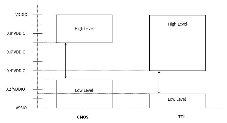
Digital output driver
The digital output driver drives the pins. It consists of circuitry to implement different drive modes and slew rate control for the digital output signals. The HSIOM selects the control source for the output driver. The two primary types of control sources are Port Configuration registers and Fixed Function Digital peripherals. A particular HSIOM connection is selected by writing to the HSIOM Port Select register (
HSIOM_PRTx_PORT_SEL
).
Each GPIO pin has ESD diodes to clamp the pin voltage to the I/O supply source. Ensure that the voltage at the pin does not exceed the I/O supply voltage VDDIO/VDDD/VDDA or drop below VSSIO/VSSD/VSSA. For the absolute maximum and minimum GPIO voltage, see the device datasheet.
The Output Data register (
GPIO_PRTx_OUT
) associated with the output pin enables or disables the digital output driver in the hardware. Peripherals other than the GPIO port, directly control both the output and the output enable signals of the output buffer.
Slew rate control
Some GPIO pins have fast and slow output slew rate options for the strong drivers configured using the SLOW bit of the Port Output Configuration register (
GPIO_PRTx_CFG_OUT
). By default, this bit is cleared and the port works in fast slew mode. This bit can be set if a slow slew rate is required. Slower slew rate results in reduced EMI and crosstalk and is recommended for low-frequency signals or signals without strict timing constraints.
When configured for a fast slew rate, the drive strength can be set to one of four levels using the
GPIO_PRTx_CFG_OUT.DRIVE_SELy
. The drive strength field determines the active portion of the output driver used and can affect the slew rate of output signals. Drive strength options are full drive strength (default), one-half strength, and one-quarter strength. Drive strength must be set to full drive strength when the slow slew rate bit (SLOW) is set.
Drive select | DRIVE_SEL[0:1] | Description |
|---|---|---|
DRIVE_SEL_THREE | 11 | 1/8 drive strength: GPIO drives current at one-eighth of its maximum rated specification. |
DRIVE_SEL_TWO | 10 | 1/4 drive strength: GPIO drives current at one-quarter of its maximum rated specification. |
DRIVE_SEL_ONE | 01 | 1/2 drive strength: GPIO drives current at one-half of its maximum rated specification |
DRIVE_SEL_ZERO | 00 | Full drive strength: GPIO drives current at its maximum rated specification. |
Drive strength
The drive strength of an I/O specifies how much current I/O pin can drive and sink while maintaining the minimum VOH and VOL levels. When the output is configured for fast slew rate, the drive strength can be set to one of four levels using the DRIVE_SEL field of the port output configuration register (
GPIO_PRTx_CFG_OUT
). The drive strength field determines the active portion of the output driver used and can affect the slew rate of output signals. Drive strength options are full drive strength (default), one-half strength, one-quarter strength, and one-eighth strength. Drive strength must be set to full drive strength when the slow slew rate bit (SLOW) is set.
The I/O port provides 2 advanced registers called as Port output Drive Select Extension Register (
GPIO_PRTx_CFG_DRIVE_EXT[0-1]
) to configure the drive width of each pin of the respective port.
Also, there is Port output configuration register 2 (
GPIO_PRTx_CFG_OUT2
) to control the drive select trim of each pin of the respective port.
Drive select | DS_TRIM[0:2] | Description |
|---|---|---|
DEFAULT | 000 | Default (50 Ω) |
DS_15OHM | 111 | 15 Ω |
DS_20OHM | 110 | 20 Ω |
DS_30OHM | 101 | 30 Ω |
DS_50OHM | 100 | 50 Ω |
DS_60OHM | 011 | 60 Ω |
DS_90OHM | 010 | 90 Ω |
DS_120OHM | 001 | 150 Ω |
Drive mode
Each I/O is individually configurable to one of eight drive modes by the DRIVE_MODE[7:0] field of the Port Configuration register (
GPIO_PRTx_CFG
).
lists the drive modes using
GPIO_PRTx_CFG
register. It provides a comprehensive breakdown of the different modes in two distinct columns: GPIO functionality and fixed peripheral functionality.
Note:
OUT_EN is not user-configurable; its value is set according to the pin mode. For example, in GPIO mode OUT_EN = 1. See
Table 143
Drive mode | Value | GPIO port configuration register, AMUXBUS | Fixed-function digital peripheral | ||||||
|---|---|---|---|---|---|---|---|---|---|
OUT_EN = 1 | OUT_EN = 0 | OUT_EN = 1 | OUT_EN = 0 | ||||||
OUT = 1 | OUT = 0 | OUT = 1 | OUT = 0 | OUT = 1 | OUT = 0 | OUT = 1 | OUT = 0 | ||
High impedance | 0 | High-Z | High-Z | High-Z | High-Z | High-Z | High-Z | High-Z | High-Z |
Reserved | 1 | - | - | - | - | - | - | - | - |
Resistive pull up | 2 | Weak 1 | Strong 0 | High-Z | High-Z | Strong 1 | Strong 0 | Weak 1 | Weak 1 |
Resistive pull down | 3 | Strong 1 | Weak 0 | High-Z | High-Z | Strong 1 | Strong 0 | Weak 0 | Weak 0 |
Open drain, drives low | 4 | High-Z | Strong 0 | High-Z | High-Z | Strong 1 | Strong 0 | High-Z | High-Z |
Open drain, drives high | 5 | Strong 1 | High-Z | High-Z | High-Z | Strong 1 | Strong 0 | High-Z | High-Z |
Strong | 6 | Strong 1 | Strong 0 | High-Z | High-Z | Strong 1 | Strong 0 | High-Z | High-Z |
Resistive pull up or pull down | 7 | Weak 1 | Weak 0 | High-Z | High-Z | Strong 1 | Strong 0 | Weak 1 | Weak 0 |
Figure 83.
GPIO port, drive mode block diagrams
is an output driver diagram that shows the pin view for fixed-function-based peripherals in all available drive modes.
Figure 84.
Fixed Function Peripheral I/O drive mode block diagrams
High-impedance(0)
High-impedance mode is the standard high-impedance (High-Z) state recommended for analog and digital inputs. For digital signals, the input buffer is enabled; for analog signals, the input buffer is typically disabled to reduce crowbar current and leakage in low-power designs. To achieve the lowest device current, unused GPIOs must be configured to the high-impedance drive mode with input buffer disabled. High-impedance drive mode with input buffer disabled is also the default pin reset state
Resistive pull-up mode(2) and resistive pull-down mode(3)
Resistive modes provide a series resistance in one of the data states and strong drive in the other. Pins can be used for either digital input or digital output in these modes. If resistive pull-up is required, a '1' must be written to that pin's data register bit. If resistive pull-down is required, a '0' must be written to that pin's data register. Interfacing mechanical switches is a common application of these drive modes. The resistive modes are also used to interface the MCU with open drain drive lines. Resistive pull-up is used when the input is open drain low and resistive pull-down is used when the input is open drain HIGH
Open drain drives low(4) and open drain drives high(5)
Open drain modes provide high impedance in one of the data states and strong drive in the other. Pins are useful as digital inputs or outputs in these modes. Therefore, these modes are widely used in bidirectional digital communication. Open drain drive high mode is used when the signal is externally pulled down and open drain drive low is used when the signal is externally pulled high. A common application for the open drain drive low mode is driving I2C bus signal lines
Strong drive(6)
The strong drive mode is the standard digital output mode for pins; it provides a strong CMOS output drive in both high and low states. Strong drive mode pins should not be used as inputs under normal circumstances. This mode is often used for digital output signals or to drive external devices
Resistive pull-up or resistive pull-down(7)
In the resistive pull-up or pull-down mode, the GPIO will have a series resistance in both logic 1 and logic 0 output states. The high data state is pulled up while the low data state is pulled down. This mode is useful when the pin is driven by other signals that may cause shorts
Firmware-controlled GPIO
For standard firmware-controlled GPIO using registers, the GPIO mode must be selected in the
HSIOM_PRTx_PORT_SEL
register.
The
GPIO_PRTx_OUT
register is used to read and write the output buffer state for GPIOs. A write operation to this register changes the GPIO's output driver state to the written value. A read operation reflects the output data written to this register and the resulting output driver state. It does not return the current logic level present on GPIO pins, which may be different. Using the
GPIO_PRTx_OUT
register, read-modify-write sequences can be safely performed on a port that has both input and output GPIOs.
In addition to the Data register, the following three registers are provided to set, clear, and invert the output data respectively on specific pins in a port without affecting other pins:
GPIO_PRTx_OUT_SET
,
GPIO_PRTx_OUT_CLR
, and
GPIO_PRTx_OUT_INV
. This avoids the need for read-modify- write operations in most use cases. Writing '1' to these register bit fields will set, clear, or invert the respective pin; writing '0' will have no effect on the pin state.
GPIO_PRTx_IN
is the Port I/O Pad register that provides the actual logic level present on the GPIO pin when read. Writes to this register have no effect.
Interrupt
All port pins have the capability to generate interrupts. There are two routing possibilities for pin signals to generate interrupts, as shown in
Figure 85
.
Figure 85.
Interrupt signal routing
Pin signals through the ‘GPIO edge detect’ block with direct connection to the CPU interrupt controller. Interrupt generation is independent of HSIOM configuration, consider disabling it (
GPIO_PRTx_INTR_CFG.EDGEy_SEL
= 00) to avoid unwanted GPIO interrupt.
Figure 86
shows the block diagram of the GPIO Edge Detect block.
Each GPIO pin interrupt can be activated either on GPIO pin rising or GPIO pin falling edge changes based on
GPIO_PRTx_INTR_CFG
register selection. Each of the up to eight GPIO pads in an I/O port has interrupt cause fields that are set to ‘1’ on a GPIO pin input signal rising and falling edge respectively (
GPIO_PRTx_INTR
register). The
GPIO_PRTx_INTR_MASK
register of the I/O port specifies which interrupt is propagated to its interrupt output. This propagated GPIO pin interrupt is a deep sleep functionality interrupt and this allows for a GPIO input signal change to wake up the CPU from deep sleep power mode after combined with other given GPIO port “i” pin interrupts as shown in
Figure 86
to form a port interrupt interrupts_gpio[i].
In addition, a register field specifies one specific I/O input signal that is routed to a 50-ns glitch filter (
GPIO_PRTx_INTR_CFG.FLT_SEL
register). The glitch filter output has a dedicated detection circuitry and has dedicated detection control fields (such as
GPIO_PRTx_INTR.FLT_EDGE
). Each I/O port has a dedicated interrupt associated to it (interrupts_gpio[i] for I/O port i).
Figure 85
illustrates the interrupt functionality.
Figure 86
shows the GPIO edge detect block architecture.
Figure 86.
GPIO edge detect block architecture
The software ISR can read the 8+1 interrupt cause fields to determine the I/O or glitch filter signal(s) that caused the interrupt activation. The ISR needs to clear the interrupt cause fields to deactivate the interrupt.
An edge detector is present at each pin. It is capable of detecting rising edge, falling edge, and both edges without any reconfiguration. The edge detector is configured by writing into the
GPIO_PRTx_INTR_CFG.EDGEy_SEL
field, as shown in
Table 148
.
EDGE_SEL | Configuration |
|---|---|
00 | Interrupt is disabled |
11 | Interrupt on both edges |
10 | Interrupt on falling edge |
01 | Interrupt on rising edge |
Writing '1' to the corresponding status bit clears the pin edge state. It is important to clear the edge state status bit; otherwise, an interrupt can occur repeatedly for a single trigger or respond only once for multiple triggers, which is explained later in this section. When the Port Interrupt Control Status register is read at the same time an edge is occurring on the corresponding port, it can result in the edge not being properly detected. Therefore, when using GPIO interrupts, it is recommended to read the Status register only inside the corresponding interrupt service routine and not in any other part of the code.
Firmware and the debug interface are able to trigger a hardware interrupt from any pin by setting the corresponding bit in the
GPIO_PRTx_INTR_SET
register.
In addition to the pins, each port provides a glitch filter connected to its own edge detector. This filter can be driven by one of the pins of a port. The selection of the driving pin is done by writing to the
GPIO_PRTx_INTR_CFG.FLT_SEL
field as shown in
Table 149
.
FLT_SEL | Selected pin |
|---|---|
000 | Pin 0 is selected |
001 | Pin 1 is selected |
010 | Pin 2 is selected |
011 | Pin 3 is selected |
100 | Pin 4 is selected |
101 | Pin 5 is selected |
110 | Pin 6 is selected |
111 | Pin 7 is selected |
When a port pin edge occurs, it is required to know which pin caused the edge. This is done by reading the port Interrupt Status register (
GPIO_PRTx_INTR
). This register includes both the latched information on which pin detected an edge and the current pin status. This allows the CPU to read both information in a single read operation. This register has an additional use - to clear the latched edge state.
The
GPIO_PRTx_INTR_MASK
register enables forwarding of the
GPIO_PRTx_INTR
edge detect signal to the interrupt controller when a '1' is written to a pin's corresponding bit field. The
GPIO_PRTx_INTR_MASKED
register can then be read to determine the specific pin that generated the interrupt signal forwarded to the interrupt controller. The masked edge detector outputs of a port are then ORed together and routed to the interrupt controller (NVIC in the CPU subsystem). Thus, there is only one interrupt vector per port.
The masked and ORed edge detector block output is routed to the interrupt source multiplexer, which gives an option of level and rising edge detection. If the Level option is selected, an interrupt is triggered repeatedly as long as the port interrupt status register bit is set. If the rising edge detect option is selected, an interrupt is triggered only once if the Port Interrupt Status register is not cleared. Thus, it is important to clear the interrupt status bit if the edge detect block is used.
There is a dedicated interrupt vector for each port when the interrupt signal is routed through the fixed-function route.
All the port interrupt vectors are also ORed together into a single interrupt vector for use on devices with more ports than there are interrupt vectors available. To determine the port that triggered the interrupt, the
GPIO_INTR_CAUSEx
registers can be read. A '1' present in a bit location indicates that the corresponding port has a pending interrupt. The indicated
GPIO_PRTx_INTR
register can then be read to determine the pin source.
The
GPIO_VDD_ACTIVE
register provides the capability to read the state of the external power supplies. It indicates the absence or presence of VDDIO supplies, VDDA, and VDDD. In addition, power supply interrupts can be configured to generate interrupts on supply state change. The
GPIO_VDD_INTR_MASK
register is used to mask or enable the forwarding of an interrupt to the CPUs. The status of an interrupt can be checked with the
GPIO_VDD_INTR
register.
Analog I/O
Analog resources, such as LPCOMP and external crystal pins for ECO and WCO, which require low-impedance routing paths, have fixed pins. These pins provide direct connections to specific analog blocks using the AMUXBUS. They help improve performance and should be given priority over other pins when using these analog resources. See the device datasheet for details on these dedicated pins. To configure a GPIO as an analog pin connecting to AMUXBUS, it should be configured in high-impedance analog mode with the input buffer disabled and then routed to the correct AMUXBUS using the HSIOM_PORT_SELx register.
Secure GPIO
Secure GPIO provides secure configuration per IO pin. All IO pins default to Non-secure. All AHB accesses associated with the pin configuration are subjected to the security attribute check as below:
Secure transactions can only access MMIO registers for pins that are configured as Secure
Non-secure transactions can only access MMIO registers for pins that are configured as Non-secure
Violation of the above rules results in Read Zero Write Ignore (RZWI) behavior. Therefore, software needs to ensure that the function/peripheral selected (via
HSIOM_PRTx.PORT_SEL0.IOy_SEL
) to access the IO pin has a matching security profile.
For MMIO registers common to all ports, and registers that are organized per port are exempted from this check. If a security check is required to access these MMIO registers, it must be placed in a secure region that is protected by a PPC.
Programmable digital (Smart I/O)
The Smart I/O block adds programmable logic to an I/O port. This programmable logic integrates board-level Boolean logic functionality such as AND, OR, and XOR into the port.
The Smart I/O block has the following features:
Integrate board-level Boolean logic functionality into a port
Ability to preprocess HSIOM input signals from the GPIO port pins
Ability to postprocess HSIOM output signals to the GPIO port pins
Support in all device power modes except Hibernate
Integrate closely to the I/O pads, providing the shortest signal paths with programmability
Overview
The Smart I/O block is positioned in the signal path between the HSIOM and the I/O port. The HSIOM multiplexes the output signals from fixed-function peripherals and CPU to a specific port pin and conversely. The position of the Smart I/O block in this signal path enables it to act as a bridge that can process signals between port pins and HSIOM, as shown in
Figure 87
.
Figure 87.
Smart I/O interface
The signal paths supported through the Smart I/O block as shown in
Figure 87
are as follows:
Implement self-contained logic functions that directly operate on port I/O signals
Implement self-contained logic functions that operate on HSIOM signals
Operate on and modify HSIOM output signals and route the modified signals to port I/O signals
Operate on and modify port I/O signals and route the modified signals to HSIOM input signals
The following sections discuss the Smart I/O block components, routing, and configuration in detail. In these sections, GPIO signals (io_data) refer to the input/output signals connected to the I/O port; device or chip (chip_data) signals refer to the input/output signals connected to HSIOM.
Block components
The internal logic of the Smart I/O includes the following components:
Clock and reset
Synchronizers (Sync)
Three-input look-up table (LUT)
Data unit (DU)
shows the Smart I/O internal routing.
Figure 88.
Smart I/O internal routing
Clock and reset
The clock and reset component selects the Smart I/O block’s clock (clk_block) and reset signal (rst_block_n). A single clock and reset signal is used for all components in the block. The clock and reset sources are determined by the CLOCK_SRC[4:0] bitfield of the
SMARTIO_PRTx_CTL
register. The selected clock is used for the synchronous logic in the block components, which includes the I/O input synchronizers, LUT, and data unit components. The selected reset is used to asynchronously reset the synchronous logic in the LUT and data unit components.
Note:
The selected clock (clk_block) for the block’s synchronous logic is not phase-aligned with other synchronous logic in the device, operating on the same clock. Therefore, communication between Smart I/O and other synchronous logic should be treated as asynchronous.
The following clock sources are available for selection:
GPIO input signals “io_data_in[7:0]”. These clock sources have no associated reset
HSIOM output signals “chip_data[7:0]”. These clock sources have no associated reset
Smart I/O clock (clk_smartio). This is derived from the system clock (clk_sys) using a peripheral clock divider. See the clock section for details on peripheral clock dividers. This clock is available only in Active power mode. The clock can have one out of two associated resets: rst_sys_act_n and rst_sys_dpslp_n
These resets determine in which power modes the block synchronous state is reset; for example, rst_sys_act_n is intended for Smart I/O synchronous functionality in Active power mode
Low-frequency system clock (clk_lf). This clock is available in Deep Sleep power mode. This clock has an associated reset, rst_lf_dpslp_n. Reset is activated if the device enters Hibernate mode, or is at POR
When the block is enabled, the selected clock (clk_block) and associated reset (rst_block_n) are provided to the fabric components. When the fabric is disabled, no clock is released to the fabric components and the reset is activated (the LUT and data unit components are set to the reset value of ‘0’).
The I/O input synchronizers introduce a delay of two clk_block cycles (when synchronizers are enabled). As a result, in the first two cycles, the block may be exposed to stale data from the synchronizer output. Hence, during the first two clock cycles, the reset is activated and the block is in bypass mode.
Register[BIT_POS] | Bit Name | Description |
|---|---|---|
| CLOCK_SRC[4:0] | Clock (clk_fabric)/reset (rst_fabric_n) source selection: 0: io_data_in0/1 ... 7: io_data_in[7]/1 8: chip_data0/1 ... 15: chip_data[7]/1 16: : clk_smartio/rst_sys_act_n. Used for Active functionality synchronous logic on "clk_smartio". This selection is intended for synchronous operation on a PCLK specified clock frequency ("clock_smartio_pos_en"). 17: clk_smartio/rst_sys_dpslp_n. Used for Deep Sleep functionality synchronous logic on "clk_smartio" (note that "clk_smartio" is NOT available in DeepSleep and Hibernate power modes). This selection is intended for synchronous operation on a PCLK specified clock frequency 18: same as 17 19: clk_lf/rst_lf_dpslp_n. This selection is intended for synchronous operation on"clk_lf". 20-30: The clock source is a constant '0'. Any of these clock sources should be selected when Smart I/O is disabled to ensure low power consumption. 31: clk_sys/1. This selection is intended for asynchronous operation. The Smart I/O is fully functional (reset is deactivated) after two clock edges of the selected clock. |
Synchronizer
Each GPIO input signal and device input signal (HSIOM input) can be used either asynchronously or synchronously. To use the signals synchronously, a double flip-flop synchronizer, as shown in
Figure 89
, is placed on both these signal paths to synchronize the signal to the Smart I/O clock (clk_block). The synchronization for each pin/input is enabled or disabled by setting or clearing the IO_SYNC_EN[i] bitfield for GPIO input signal and CHIP_SYNC_EN[i] for HSIOM signal in the
SMARTIO_PRTx_SYNC_CTL
register, where ‘i’ is the pin number.
Figure 89.
Smart I/O clock synchronizer
Lookup table (LUT)
Each Smart I/O block contains eight lookup table (LUT) components. The LUT component consists of a three-input LUT and a flip-flop. Each LUT block takes three input signals and generates an output based on the configuration set in the
SMARTIO_PRTx_LUT_CTLy
register (y denotes the LUT number). For each LUT, the configuration is determined by an 8-bit lookup vector LUT[7:0] and a 2-bit opcode OPC[1:0] in the
SMARTIO_PRTx_LUT_CTLy
register. The 8-bit vector is used as a lookup table for the three input signals. The 2-bit opcode determines the usage of the flip-flop. The LUT configuration for different opcodes is shown in
Figure 90
.
The
SMARTIO_PRTx_LUT_SELy
registers select the three input signals (tr0_in, tr1_in, and tr2_in) going into each LUT. The input can come from the following sources:
Data unit output
Other LUT output signals (tr_out)
HSIOM output signals (chip_data[7:0])
GPIO input signals (io_data[7:0])
LUT_TR0_SEL[3:0] bits of the
SMARTIO_PRTx_LUT_SELy
register selects the tr0_in signal for the y
th
LUT. Similarly, LUT_TR1_SEL[3:0] bits and LUT_TR2_SEL[3:0] bits select the tr1_in and tr2_in signals, respectively. For more details, see
Table 151
.
Register[BIT_POS] | Bit Name | Description |
|---|---|---|
| LUT[7:0] | LUT configuration. Depending on the LUT opcode (LUT_OPC), the internal state, and the LUT input signals tr0_in, tr1_in, and tr2_in, the LUT configuration is used to determine the LUT output signal and the next sequential state. |
| LUT_OPC[1:0] | The LUT opcode specifies the LUT operation as illustrated in Figure 90 |
| LUT_TR0_SEL[3:0] | LUT input signal “tr0_in” source selection: 0: Data unit output 1: LUT 1 output 2: LUT 2 output 3: LUT 3 output 4: LUT 4 output 5: LUT 5 output 6: LUT 6 output 7: LUT 7 output 8: chip_data0 (for LUTs 0, 1, 2, 3); chip_data[4] (for LUTs 4, 5, 6, 7) 9: chip_data1 (for LUTs 0, 1, 2, 3); chip_data[5] (for LUTs 4, 5, 6, 7) 10: chip_data2 (for LUTs 0, 1, 2, 3); chip_data[6] (for LUTs 4, 5, 6, 7) 11: chip_data3 (for LUTs 0, 1, 2, 3); chip_data[7] (for LUTs 4, 5, 6, 7) 12: io_data_in0 (for LUTs 0, 1, 2, 3); io_data[4] (for LUTs 4, 5, 6, 7) 13: io_data_in1 (for LUTs 0, 1, 2, 3); io_data[5] (for LUTs 4, 5, 6, 7) 14: io_data_in2 (for LUTs 0, 1, 2, 3); io_data[6] (for LUTs 4, 5, 6, 7) 15: io_data_in3 (for LUTs 0, 1, 2, 3); io_data[7] (for LUTs 4, 5, 6, 7) |
| LUT_TR1_SEL[3:0] | LUT input signal “tr1_in” source selection: 0: LUT 0 output 1: LUT 1 output 2: LUT 2 output 3: LUT 3 output 4: LUT 4 output 5: LUT 5 output 6: LUT 6 output 7: LUT 7 output 8: chip_data0 (for LUTs 0, 1, 2, 3); chip_data[4] (for LUTs 4, 5, 6, 7) 9: chip_data1 (for LUTs 0, 1, 2, 3); chip_data[5] (for LUTs 4, 5, 6, 7) 10: chip_data2 (for LUTs 0, 1, 2, 3); chip_data[6] (for LUTs 4, 5, 6, 7) 11: chip_data3 (for LUTs 0, 1, 2, 3); chip_data[7] (for LUTs 4, 5, 6, 7) 12: io_data_in0 (for LUTs 0, 1, 2, 3); io_data[4] (for LUTs 4, 5, 6, 7) 13: io_data_in1 (for LUTs 0, 1, 2, 3); io_data[5] (for LUTs 4, 5, 6, 7) 14: io_data_in2 (for LUTs 0, 1, 2, 3); io_data[6] (for LUTs 4, 5, 6, 7) 15: io_data_in3 (for LUTs 0, 1, 2, 3); io_data[7] (for LUTs 4, 5, 6, 7) |
| LUT_TR2_SEL[3:0] | LUT input signal “tr2_in” source selection. The encoding is the same as for LUT_TR1_SEL. |
Figure 90.
Smart I/O LUT configuration
Data unit (DU)
Each Smart I/O block includes a data unit (DU) component. The DU consists of a simple 8-bit datapath. It is capable of performing simple increment, decrement, increment/decrement, shift, and AND/OR operations. The operation performed by the DU is selected using a 4-bit opcode DU_OPC[3:0] bitfield in the
SMARTIO_PRTx_DU_CTL
register.
The DU component supports up to three input trigger signals (tr0_in, tr1_in, tr2_in) similar to the LUT component. These signals are used to initiate an operation defined by the DU opcode. In addition, the DU also includes two 8-bit data inputs (data0_in[7:0] and data1_in[7:0]) that are used to initialize the 8-bit internal state (data[7:0]) or to provide a reference. The 8-bit data input source is configured as:
Constant ‘0x00’
io_data_in[7:0]
chip_data_in[7:0]
DATA[7:0] bitfield of
SMARTIO_PRTx_DATA
register
The trigger signals are selected using the DU_TRx_SEL[3:0] bitfield of the
SMARTIO_PRTx_DU_SEL
register. The DUT_DATAx_SEL[1:0] bits of the
SMARTIO_PRTx_DU_SEL
register select the 8-bit input data source. The size of the DU (number of bits used by the datapath) is defined by the DU_SIZE[2:0] bits of the
SMARTIO_PRTx_DU_CTL
register. See the block diagram in
Figure 91
for register control details.
Figure 91.
Data unit (DU)
See
Table 152
for register control details.
Register[BIT_POS] | Bit name | Description |
|---|---|---|
| DU_SIZE[2:0] | Size/width of the data unit (in bits) is DU_SIZE+1. For example, if DU_SIZE is 7, the width is 8 bits. |
| DU_OPC[3:0] | The data unit opcode specifies the data unit operation: 1: INCR 2: DECR 3: INCR_WRAP 4: DECR_WRAP 5: INCR_DECR 6: INCR_DECR_WRAP 7: ROR 8: SHR 9: AND_OR 10: SHR_MAJ3 11: SHR_EQL Otherwise: Undefined. |
| DU_TR0_SEL[3:0] | Data unit input signal “tr0_in” source selection: 0: Constant '0'. 1: Constant '1'. Data unit output. 10–3: LUT 7–0 outputs. Otherwise: Undefined. |
| DU_TR1_SEL[3:0] | Data unit input signal “tr1_in” source selection. Encoding same as DU_TR0_SEL |
| DU_TR2_SEL[3:0] | Data unit input signal “tr2_in” source selection. Encoding same as DU_TR0_SEL |
| DU_DATA0_SEL[1:0] | Data unit input data “data0_in” source selection: 0: 0x00 1: chip_data[7:0] 2: io_data[7:0] 3: SMARTIO_PRTx_DATA.DATA[7:0] register field |
| DU_DATA1_SEL[1:0] | Data unit input data “data1_in” source selection. Encoding same as DU_DATA0_SEL. |
| DATA[7:0] | Data unit input data source. |
The DU generates a single output trigger signal (tr_out). The internal state (du_data[7:0]) is captured in flip-flops and requires clk_block.
The following pseudo code describes the various datapath operations supported by the DU opcode. Note that “Comb” describes the combinatorial functionality – that is, functions that operate independent of previous output states. “Reg” describes the registered functionality – that is, functions that operate on inputs and previous output states (registered using flip-flops).
// The following is shared by all operations.
mask
=
(
2
^
(
DU_SIZE
1
)
–
1
)
data_eql_data1_in
=
(
data
&
mask
)
==
(
data1_in
&
mask
)
)
;
data_eql_
0
=
(
data
&
mask
)
==
0
)
;
data_incr
=
(
data
1
)
&
mask
;
data_decr
=
(
data
1
)
&
mask
;
data0_masked
=
data_in0
&
mask
;
// INCR operation: increments data by 1 from an initial value (data0) until it reaches a
// final value (data1).
Comb
:
tr_out
=
data_eql_data1_in
;
Reg
:
data
<=
data
;
if
(
tr0_in
)
data
<=
data0_masked
;
//tr0_in is reload signal - loads masked data0
// into data
else
if
(
tr1_in
)
data
<=
data_eql_data1_in
?
data
:
data_incr
;
//increment data until
// it equals data1
// INCR_WRAP operation: operates similar to INCR but instead of stopping at data1, it
// wraps around to data0.
Comb
:
tr_out
=
data_eql_data1_in
;
Reg
:
data
<=
data
;
if
(
tr0_in
)
data
<=
data0_masked
;
else
if
(
tr1_in
)
data
<=
data_eql_data1_in
?
data0_masked
:
data_incr
;
// DECR operation: decrements data from an initial value (data0) until it reaches 0.
Comb
:
tr_out
=
data_eql_
0
;
Reg
:
data
<=
data
;
if
(
tr0_in
)
data
<=
data0_masked
;
else
if
(
tr1_in
)
data
<=
data_eql_
0
?
data
:
data_decr
;
// DECR_WRAP operation: works similar to DECR. Instead of stopping at 0, it wraps around
// to data0.
Comb
:
tr_out
=
data_eql_
0
;
Reg
:
data
<=
data
;
if
(
tr0_in
)
data
<=
data0_masked
;
else
if
(
tr1_in
)
data
<=
data_eql_
0
?
data0_masked
:
data_decr
;
// INCR_DECR operation: combination of INCR and DECR. Depending on trigger signals
// it either starts incrementing or decrementing. Increment stops at data1 and decrement
// stops at 0.
Comb
:
tr_out
=
data_eql_data1_in
|
data_eql_
0
;
Reg
:
data
<=
data
;
if
(
tr0_in
)
data
<=
data0_masked
;
// Increment operation takes precedence over
// decrement when both signal are available
else
if
(
tr1_in
)
data
<=
data_eql_data1_in
?
data
:
data_incr
;
else
if
(
tr2_in
)
data
<=
data_eql_
0
?
data
:
data_decr
;
// INCR_DECR_WRAP operation: same functionality as INCR_DECR with wrap around to data0 on
// reaching the limits.
Comb
:
tr_out
=
data_eql_data1_in
|
data_eql_
0
;
Reg
:
data
<=
data
;
if
(
tr0_in
)
data
<=
data0_masked
;
else
if
(
tr1_in
)
data
<=
data_eql_data1_in
?
data0_masked
:
data_incr
;
else
if
(
tr2_in
)
data
<=
data_eql_
0
?
data0_masked
:
data_decr
;
// ROR operation: rotates data right and LSb is sent out. The data for rotation is taken
// from data0.
Comb
:
tr_out
=
data
[
0
]
;
Reg
:
data
<=
data
;
if
(
tr0_in
)
data
<=
data0_masked
;
else
if
(
tr1_in
)
(
data
<=
(
0
,
data
[
7
:
1
]
)
&
mask
;
//Shift right operation
data
[
du_size
]
<=
data
[
0
]
;
//Move the data0 (LSb) to MSb
)
// SHR operation: performs shift register operation. Initial data (data0) is shifted out
// and data on tr2_in is shifted in.
Comb
:
tr_out
=
data
[
0
]
;
Reg
:
data
<=
data
;
if
(
tr0_in
)
data
<=
data0_masked
;
else
if
(
tr1_in
)
(
data
<=
(
0
,
data
[
7
:
1
]
)
&
mask
;
//Shift right operation
data
[
du_size
]
<=
tr2_in
;
//tr2_in Shift in operation
)
// SHR_MAJ3 operation: performs the same functionality as SHR. Instead of sending out
// the shifted out value, it sends out a '1' if in the last three samples/shifted-out
// values (data0), the signal high in at least two samples. otherwise, sends a '0'.
// This function sends out the majority of the last three samples.
Comb
:
tr_out
=
(
data
==
0x03
)
|
(
data
==
0x05
)
|
(
data
==
0x06
)
|
(
data
==
0x07
)
;
Reg
:
data
<=
data
;
if
(
tr0_in
)
data
<=
data0_masked
;
else
if
(
tr1_in
)
(
data
<=
(
0
,
data
[
7
:
1
]
)
&
mask
;
data
[
du_size
]
<=
tr2_in
;
)
// SHR_EQL operation: performs the same operation as SHR. Instead of shift-out, the
// output is a comparison result (data0 == data1).
Comb
:
tr_out
=
data_eql_data1_in
;
Reg
:
data
<=
data
;
if
(
tr0_in
)
data
<=
data0_masked
;
else
if
(
tr1_in
)
(
data
<=
(
0
,
data
[
7
:
1
]
)
&
mask
;
data
[
du_size
]
<=
tr2_in
;
)
// AND_OR operation: ANDs data1 and data0 along with mask; then, ORs all the bits of
// the ANDed output.
Comb
:
tr_out
=
|
(
data
&
data1_in
&
mask
)
;
Reg
:
data
<=
data
;
if
(
tr0_in
)
data
<=
data0_masked
;
Routing
The Smart I/O block includes many switches that are used to route the signals in and out of the block and also between various components present inside the block. The routing switches are handled through the
PRTGIO_PRTx_LUT_SELy
and
SMARTIO_PRTx_DU_SEL
registers. For more details, see the register reference manual. The Smart I/O internal routing is shown in
Figure 88
. In the figure, note that LUT7 to LUT4 operate on io_data/chip_data[7] to io_data/chip_data[4] whereas LUT3 to LUT0 operate on io_data/chip_data3 to io_data/chip_data0.
Operation
The Smart I/O block should be configured and operated as follows:
Before enabling the block, all the components and routing should be configured as explained in
Block components
In addition to configuring the components and routing, some block level settings must be configured correctly for the desired operation.
Bypass control: The Smart I/O path can be bypassed for a particular GPIO signal by setting the BYPASS[i] bitfield in the
SMARTIO_PRTx_CTL
register. When bit ‘i’ is set in the BYPASS[7:0] bitfield, the i
th
GPIO signal is bypassed to the HSIOM signal path directly – Smart I/O logic will not be present in that signal path. This is useful when the Smart I/O function is required only on select I/Os
Pipelined trigger mode: The LUT input multiplexers and the LUT component itself do not include any combinatorial loops. Similarly, the data unit also does not include any combinatorial loops. However, when one LUT interacts with the other or to the data unit, inadvertent combinatorial loops are possible. To overcome this limitation, the PIPELINE_EN bitfield of the
SMARTIO_PRTx_CTL
register is used. When set, all the outputs (LUT and DU) are registered before branching out to other components
After the Smart I/O block is configured for the desired functionality, the block can be enabled by setting the ENABLED bitfield of the
SMARTIO_PRTx_CTL
register. If disabled, the Smart I/O block is put in bypass mode, where the GPIO signals are directly controlled by the HSIOM signals and conversely. The Smart I/O block must be configured; that is, all register settings must be updated before enabling the block to prevent glitches during register updates
Register [BIT_POS] | Bit Name | Description |
|---|---|---|
| PIPELINE_EN | Enable for pipeline register: 0: Disabled (register is bypassed). 1: Enabled |
| ENABLED | Enable Smart I/O. Set to '1' only when the Smart I/O is completely configured: 0: Disabled (signals are bypassed; behavior as if BYPASS[7:0] is 0xFF). When disabled, the block (data unit and LUTs) reset is activated. If the block is disabled: - The PIPELINE_EN register field should be set to '1', to ensure low power consumption. - The CLOCK_SRC register field should be set to 20 to 30 (clock is constant '0'), to ensure low power consumption. 1: Enabled. When enabled, it takes three clk_block clock cycles until the block reset is deactivated and the block becomes fully functional. This action ensures that the I/O pins' input synchronizer states are flushed when the block is fully functional. |
| BYPASS[7:0] | Bypass of the Smart I/O, 1 bit for each I/O pin: BYPASS[i] is for I/O pin i. When ENABLED is '1', this field is used. When ENABLED is '0', this field is not used and Smart I/O is always bypassed. 0: No bypass (Smart I/O is present in the signal path) 1: Bypass (Smart I/O is absent in the signal path) |
Registers summary
Registers | Name | Description |
|---|---|---|
| Port Output register | Reads and writes the output driver data for I/O pins in the port. |
| Port Output Clear register | Clears output data of specific I/O pins in the port. |
| Port Output Set register | Sets output data of specific I/O pins in the port. |
| Port Output Invert register | Inverts output data of specific I/O pins in the port. |
| Port Input register | Reads the current pin state present on I/O pin inputs. |
| Port Interrupt Status register | Reads the current pin interrupt state. |
| Port Interrupt Mask register | Configures the mask that forwards pin interrupts to the CPU's interrupt controller. This register only masks forwarding of interrupts to the CPU’s interrupt controller; it does not enable/disable the logging of interrupts into the INTR register. |
| Port Interrupt Masked Status register | Contains the AND-ed values of and registers forwarded to the CPU interrupt controller. |
| Port Interrupt Set register | Allows firmware to set pin interrupts. |
| Port Interrupt Configuration register | Selects the edge detection type for each pin interrupt. |
| Port Configuration register | Selects the drive mode and input buffer enable for each pin. |
| Port Input Configuration register | Configures the input buffer mode (CMOS or TTL) for each pin. VTRIP_SEL[7:0]_0. |
| Port Output Configuration register | Configures the port output buffer drive strength. |
| Port Output Configuration register | Configures the port output buffer slew rate. |
| HSIOM Port Select Register | Selects the hardware peripheral connection to I/O pins. |
| Interrupt Port Cause Register | Provides interrupt status corresponding to ports (0 + z × 32) to (31 + z × 32). “z” can be from 0 to 3. |
| External Power Supply Detection Register | Provides external power supply status. |
| Supply Detection Interrupt Register | This register is set whenever a supply ramp up or ramp down is detected. Some bits may be set after system power-up, depending on power supply sequencing. |
| Supply Detection Interrupt Mask Register | Configures the supply detection interrupts for all supplies. It only masks the forwarding of interrupts to the CPUs and does not enable/disable the logging of interrupts into the VDD_INTR Register. |
| Supply Detection Interrupt Masked Register | Contains the AND-ed values of and Registers. |
| Supply Detection Interrupt Set Register | Allows a firmware or debugger to set interrupt bits in the register by writing a '1' to the corresponding bit field. When read, it returns the same value as the Register. |
| Power switch status | Provides the status of the power switch. |
| Supply Power Switch control Register | Configures inrush current limit level select, threshold select, and level set for GPIO. |
| Secure Interrupt port cause register | Provides interrupt status corresponding to ports. |
| SMARTIO Control Register | This is the control register for SMARTIO on the specific port. It controls enable, clock source, bypass, and so on |
| LUT Component Input Selection Register | LUT Input Selection Register. LUT_TR0_SEL, LUT_TR1_SEL, and LUT_TR2_SEL |
| LUT Component Control Register | Provides the opcode for LUT |
| Data Unit Component Input Selection Register | Data Unit Input Selection Register |
| Data Unit Component Control Register | Data Unit Control Register |
| Data Register | Data unit input data source |
Timer, counter, and pulse-width modulator (TCPWM)
The timer, counter, and pulse-width modulator (TCPWM) block in
PSOC™ Control C3
MCU implements a 16- or 32-bit TCPWM, motion interface (MOTIF). TCPWM includes three counter groups where Group 1 and Group 2 support up to 8 counters, and Group 0 supports up to 4 counters only. The counter can be used to measure the period and pulse width of an input signal (timer), find the number of times an event occurs (counter), and generate PWM signals. The TCPWM block works in Active and Sleep modes.
This chapter explains the features, implementation, and operational modes of the TCPWM block.
Features
The TCPWM block has the following features:
Three counter groups:
Group 1 and Group 2 support up to 8 counters. Group 0 supports up to 4 counters only
Each counter can run in one of the following function modes:
Timer-counter with compare
Timer-counter with capture
Pulse-width modulation(PWM)
PWM with dead time
A configurable motion interface (MOTIF) block (only included in Group 1)
The MOTIF module can operate in four different modes: quadrature decoder, hall sensor, stand-alone multi-channel mode, and quadrature mode with stand-alone multi-channel
Supports high-resolution PWM generation (HRPWM) feature in 32-bit TCPWM counters
HRPWM is limited to PWM and PWM_DT modes only
HRPWM support is only applicable to Group 0
16- or 32-bit counter, two compare/capture (CC0/CC1), and period registers
Counter compare, period, line_sel, and dead time registers are double-buffered
Up, down, and up/down counting modes
Clock pre-scaling (1x, 2x, 4x , 8x, 16x, 32x, 64x, 128x)
Glitch filter with configurable depth supported on General-purpose triggers used by all counters and specific One-to-one triggers for each counter
Rising edge, falling edge, combined rising/falling edge detection, or pass-through on all HW input signals to derive counter events
The start, reload, stop, capture0, and capture1 events can be generated by software
Two output trigger signals for each counter to indicate underflow, overflow, cc0_match, cc1_match, cc0_cc1_match, LINE_OUT, and TC events
Two PWM complementary output lines for each counter. Dead time insertion is 16 bits and independent for two PWM outputs
Independent control of clock pre-scaling and dead time
Configurable PWM dithering on period as well as duty cycle in Group 1 and Group 2
Configurable option to continue/pause with the ability to enter passive state through kill polarity in debug mode
Output state control for PWM signal during the stop or kill operation synchronous to period match
Independent line polarity setting for PWM signal during the kill operation
Architecture
Figure 92.
TCPWM block diagram
The three main registers that control the counters are:
COUNTER register holds the current counter value
PERIOD register holds the upper value of the counter. When the counter counts for n cycles, set this field to n-1
CC0/1 registers are used to capture the counter value in CAPTURE mode. In all other modes, they are compared to the counter value
Each counter can have 19 input trigger signals and two constant input signals, '0' and '1'; all of them are synchronized with the CLK_PERI clock.
The TCPWM block has the following interfaces:
Bus interface:
Connects the block to the CPU subsystem via the AHB-5 interface
I/O signal interface:
Consists of input triggers (such as reload, start, stop, count, and capture0/1) and output signals (such as LINE_OUT, LINE_COMPL_OUT, TR_OUT0, and TR_OUT1). All the input signals are used to trigger an event within the counter, such as a reload trigger generating a reload event. The output signals are generated by internal events (underflow, overflow, and capture/compare) and can be connected to other peripherals to trigger events
Interrupts:
Provides interrupt request signals from each counter, based on terminal count (TC), Compare/Capture CC0_match, or Compare/Capture CC1_match event
See the Registers summary for more information on all registers required for this block.
Enabling and disabling counters in a TCPWM block
A counter can be enabled by writing '1' to the corresponding ENABLE bit of the CTRL register; it can be disabled by writing '0' to the same bit.
Note:
The counter must be configured before enabling it. Disabling the counter retains the values in the configuration registers.
Clocking
The TCPWM counter can have its own clock. The only source for the clock is from the configurable peripheral clock dividers generated by the clocking system; see the
Clocking system
chapter for details. To select a clock divider for a particular counter inside a TCPWM, use the CLOCK_CTL register from the peripheral register space. In this section, the clock to the counter is called clk_counter. Event generation is performed on clk_counter. Another clock, system clock (clk_sys), is used for the pulse width of the output triggers. The system clock (clk_sys) is synchronous to clk_peri, but can be divided using CLOCK_CTL.
Clock pre-scaling
The clk_counter can be further divided inside each counter, with values of 1, 2, 4, 8, 16, 32, 64, and 128. This division is called pre-scaling. The pre-scaling is set in the PS_DIV [2:0] field of the PS register.
Count event
The counter functionality is performed on an “active count” pre-scaled clock, which is gated by a “count event” signal. For example, a counter increments or decrements by '1' every counter clock cycle in which a count event is detected.
Figure 93.
Counter clock generation
All status or output changes can only happen at the “active count” pre-scaled counter clock. In other words, if the count event is inactive, counter, status, interrupt, and all outputs do not change value. For example, if the count event is in pass through mode, and if the count event is low when the counter goes to “0” in down count mode, the terminal count (tc) event and underflow event are generated at the next pre-scaled counter clock after the count event goes high. The only exception is immediate kill mode. Kill input suppresses the PWM output immediately regardless of the “active count” pre-scaled counter clock.
Note:
Not supported in all modes
Trigger inputs
The TCPWM block has 19 Trigger_In signals and constant '0' and '1' signals, which come from other on-chip resources such as SCBs, DMA, HPPASS, and so on. The Trigger_In signals are shared with all counters inside the TCPWM block.
Two types of trigger signals are synchronized and can be used by the counters to generate events.
General-purpose triggers:
These can be used by all counters. These triggers are generated by different blocks in the system and are distributed by the trigger infrastructure (peripheral trigger multiplexers). See the
Trigger multiplexer (Trigger MUX)
chapter for more details
One-to-one triggers:
A separate set exists for each counter, that is only connected to that counter. These triggers are used for direct trigger connections from trigger sources (such as HPPASS level triggers) to associated TCPWM counters
Use the trigger mux registers, TR_IN_SEL0 and TR_IN_SEL1, to configure which signals get routed to the Trigger_In for the TCPWM block. See
Table 155
for all possible multiplexer settings selecting an input trigger event for a TCPWM block. For each event, two constant trigger inputs are available. Input trigger 0 is always constant '0' and input trigger 1 is always constant '1'.
Each counter can select any of the 21 trigger signals to be the source for any of the following events:
Capture 0 and Capture 1
Count
Reload
Stop/Kill
Start
Note:
The PERI0_TR_CMD register can be used to trigger the Reload, Stop, Start, and Capture0/1 respectively from software.
Input Trigger Selection Register | Bit field | Bits | Description |
|---|---|---|---|
TR_IN_SEL0 | CAPTURE0_SEL | 7:0 | Selects one of the 21 input triggers as a capture0 trigger. In the PWM, PWM_DT modes this trigger is used to switch the values, if the compare and period registers with their buffer counterparts. |
COUNT_SEL | 15:8 | Selects one of the 21 input triggers as a count trigger. | |
RELOAD_SEL | 23:16 | Selects one of the 21 input triggers as a reload trigger. | |
STOP_SEL | 31:24 | Selects one of the 21 input triggers as a stop trigger. In PWM, PWM_DT modes, this is the kill trigger. | |
TR_IN_SEL1 | START_SEL | 7:0 | Selects one of the 21 input triggers as a start trigger. |
CAPTURE1_SEL | 15:8 | Selects one of the up to 21 input triggers as a capture1 trigger |
The following sections describe each TCPWM mode and the function of each input event in detail.
A typical operation uses the reload event once to initialize and start the counter and the stop event to stop the counter. When the counter is stopped, the start event can be used to start the counter with its counter value unmodified from when it was stopped.
If stop, reload, and start events coincide, the following precedence relationship holds:
A stop event has a higher priority than a reload event
A reload event has a higher priority that a start event
As a result, when a reload or start event coincides with a stop event, the reload or start event has no effect.
Before going to the counter each Trigger_IN can pass through a positive edge detector, negative edge detector, both edge detector, or pass straight through to the counter. This is controlled using the TR_IN_EDGE_SEL register.
Multiple detected events are treated as follows:
In the rising edge and falling edge modes, multiple events are effectively reduced to a single event. As a result, events may be lost
In the rising/falling edge mode, an even number of events is not detected and an odd number of events is reduced to a single event. This is because the rising/falling edge mode is typically used for capture events to determine the width of a pulse. The current functionality ensures that the alternating pattern of rising and falling is maintained
Figure 94.
TCPWM input events
According to
Table 155
, a dedicated input trigger signal for trigger event generation can be defined by the TR_IN_SEL0 and TR_IN_SEL1 registers. The selection can be done between two constant signals (constant '0' and constant '1'), specific one-to-one trigger input signals, or general-purpose input trigger signals.
Figure 94
shows how the input trigger source is selected.
The number of one-to-one (tr_one_cnt_synced) and general-purpose (tr_all_cnt_synced) input triggers are device-specific (refer to the
PSOC™ Control C3
MCU datasheet).
shows how the multiplexer should be handled for the input trigger event generation.
Input trigger selection | Input trigger | Input trigger source |
|---|---|---|
0 | constant ‘0’ | constant '0' |
1 | constant ‘1’ | constant '1' |
2 | PASS (programmable analog subsystem), through 1:1 triggermux #0 | Refer to Trigger inputs chapter |
3 | HSIOM | Refer to the “Alternate Pin Function” section in the device datasheet |
4 | HSIOM | Refer to the “Alternate Pin Function” section in the device datasheet |
5 | tr_all_cnt_in0 | Refer to the trigger mux block. |
... | ||
20 | tr_all_cnt_in[15] | Refer to the trigger mux block |
Note:
The input triggers can be generated by different sources. While the general-purpose trigger inputs (tr_all_cnt_in0 to tr_all_cnt_in[15)] are only from the trigger multiplexer block (see the
Trigger inputs
chapter), the one-to-one input triggers can also be generated by external GPIO input pins.
All trigger inputs are synchronized to a peripheral clock. When more than one event occurs in the same counter_clock period, one or more events may be missed. This can happen for high-frequency events (frequencies close to the counter frequency) and a timer configuration in which a pre-scaled (divided) counter_clock is used.
The following figure illustrates the timing on how input triggers are detected by the counter.
Figure 95.
Input trigger detection by “active count” pre-scaled counter clock
Note:
The event marked as an arrow in the figures in the following sections depicts the event that has been detected by the counter.
Typically, the count event is a constant ‘1’ and pre-scaling is off. In this case, the “active count” pre-scaled counter clock is the same as the counter clock. In other cases, edge detection may detect multiple events (on the counter clock) before the next “active count” pre-scaled counter clock on which the detected event is used. Multiple detected events are treated as follows:
In the rising edge and falling edge modes, multiple events are effectively reduced to a single event. As a result, events may be lost
In the rising/falling edge mode, an even number of events is not detected and an odd number of events is reduced to a single event. This is because the rising/falling edge mode is typically used for capture events to determine the width of a pulse. The current functionality ensures that the alternating pattern of rising, falling, rising, falling, and so on, is maintained
A pass-through event is not remembered by CLK_PERI; it affects the functionality if it lasts and can be detected by a counter-operation clock. If the pulse width of a pass-through event is less than a counter-operation clock cycle, it may get lost. Pass-through detection may result in an event that is active for multiple counter clocks. This may result in undesirable behavior of the counter and its associated trigger outputs. Use the pass-through event detection only for stop and count event types in most function modes. Pass-through mode can also be used in switch events in the PWM/PWM_DT mode, if it selects the constant high as the source.
Glitch filtering
Glitch filtering is the process of removing unwanted pulses from a digital input signal that is usually high or low. Glitch filter can be inserted to the general-purpose triggers and specific one-to-one triggers. The glitch filter runs on clk_peri.
The glitch filter can be configured through the ALL_GF register for the glitch filter that is used for general-purpose triggers and ONE_GF register for glitch filter that is used for the one-to-one triggers. The ALL_GF register and ONE_GF register is the same design in hardware and has the same register configuration setup. They are named differently to differentiate the register naming for the glitch filter that is connected to general-purpose trigger or one-to-one triggers. Each instance of the glitch filter has its own register for independent configuration.
Through the combination setting of GF_DEPTH and GFPS_DIV, user can select the depth of the glitch filter from 0 to 512.
illustrates how the output of the glitch filter changes when the duration of the input of the glitch filter is equal or greater than glitch filter depth. Otherwise, the output is unchanged from its current value.
Figure 96.
Glitch filter operation
illustrates an example on the connection of the glitch filter to general-purpose triggers and one-to-one triggers for two different TCPWM counter groups.
Synchronization of multiple counters
The previous sections described hardware-based event generation. In addition, software-based event generation is supported: the reload, start, stop, capture0, and capture1 events can be generated by writing to the PERI0_TR_CMD registers. These are counter-specific registers and allow software-based event generation only for a single counter. Synchronized software-based event generation (such as starting multiple counters synchronously) is possible by selecting the same trigger signal in all desired counters (via TR_IN_SEL0 and TR_IN_SEL1 registers) and generating a trigger by the PERI0_TR_CMD register in the PERI block.
The following figure shows an example of how to synchronously start multiple counters with TR_CMD of the PERI block.
Figure 97.
PERI TR_CMD synchronously starts counters
The following example describes the required steps to start counters synchronously:
Configure PERI_PCLK_GR5_CLOCK_CTL0/1/2 to select the same clock divider clock_div_81
Configure DIV_8_CTL1 and DIV_CMD to generate clock divider enable signal for TCPWM. Hence, three counters have the same clock divider enable signal; in other words, their clocks are synchronous
Enable the three counters one by one - counter is enabled but will not run until the start or reload event is detected
Configure the three counters start event, all selecting tr_all_cnt_in0; this means that the three counters will run synchronously when tr_all_cnt_in0 asserts
Use TR_CMD to generate a trigger pulse on TR_GROUP[9].TR_OUT0. All three counters will run synchronously
Note:
All registers listed here belong to the PERI block (see clocking system chapter).
A software-based event is set after writing TR_CMD respective bit to ‘1’, and cleared by hardware on the next “active count” pre-scaled counter clock. For some events in a specific mode, it is cleared on the next “active count” pre-scaled counter clocks that have a TC event. The event detection setting (TR_IN_EDGE_SEL) does not have an effect on a software-based event
Figure 98.
Software trigger command detection by active count pre-scaled counter clock
Trigger outputs
Each counter has two trigger output signals (TR_OUT0 and TR_OUT1) and they can be routed through the trigger mux to other peripherals on the device. The bit field OUT0 in the TR_OUT_SEL register is used to select one of the internal events to generate output trigger 0 (TR_OUT0), and the bit field OUT1 selects one of the internal events to generate TR_OUT1. Also, it allows disabling of the output triggers.
The following are the events indicated by the counter trigger output signal:
Overflow (OV): An overflow event indicates that in up counting mode, COUNTER equals the PERIOD register, and is changed to a different value
Underflow (UN): An underflow event indicates that in down counting mode, COUNTER equals 0, and changes to a different value
TC (Terminal count): A TC event is the logical OR of the underflow and overflow events
CC0/1_MATCH: This event is generated when the counter is running and one of the following conditions occurs:
Counter equals the compare value. This event is either generated when the match is about to occur (COUNTER does not equal CC0/1 and changes to CC0/1) or when the match is not about to occur (COUNTER equals CC0/1 and changes to a different value)
A capture event has occurred and the CC0 (CC1) and CC0_BUFF (CC1_BUFF) registers are updated
CC0_CC1_MATCH: This event is triggered when either CC0_MATCH or CC1_MATCH occurrs.
LINE_OUT: A PWM output signal
DISABLED: Output trigger is disabled
The selection of the events for the output trigger generation is done by the TR_OUT_SEL register. It also allows disabling the output triggers.
Note:
These signals only remain high for two cycles of CLK_SYS. For reliable operation, the condition that causes this trigger should be a maximum of one quarter of the CLK_SYS. For example, if the CLK_SYS is running at 24 MHz, the condition causing the trigger should occur at a frequency equal to or less than 6 MHz.
When LINE_OUT is selected for output triggers, the output trigger bypasses the two cycle pulses generation logic and directly outputs LINE_OUT.
The generated triggers have two main uses:
Initiating a DMA data transfer. For example, in the PWM mode with an up counting timer, the overflow can be used to transfer new period and compare values from memory to the counters' PERIOD_BUFF and CC0_BUFF registers
Reconstruction of a PWM signal in a programmable digital component. As documented in
Pulse-width modulation (PWM) mode
, the PWM line output signal is derived from the cc0_match (cc1_match), underflow, and overflow internal events. By making these internal events available as output triggers, other components can reconstruct and potentially modify the PWM signal (note the mentioned frequency restrictions)
Internal events
Underflow event
An underflow event indicates that in down counting, the COUNTER equals zero, and changes to a different value. Reload also generates an underflow event in some specific mode. The following table summarizes the underflow generation of each function mode.
Mode | UP | DOWN | UPDN1 | UPDN2 |
|---|---|---|---|---|
Timer | Counter is decremented and changes from a state in which COUNTER equals 0. Reload event in DOWN, UPDN1, and UPDN2 modes. | |||
Capture | Counter is decremented and changes from a state in which COUNTER equals 0. Reload event in DOWN, UPDN1, and UPDN2 modes. | |||
PWM | Counter is decremented and changes from a state in which COUNTER equals 0. Reload event in DOWN, UPDN1, and UPDN2 modes. | |||
PWM_DT | Counter is decremented and changes from a state in which COUNTER equals 0. Reload event in DOWN, UPDN1, and UPDN2 modes. | |||
Overflow event
An overflow event indicates that in up counting, the COUNTER equals PERIOD, and changes to a different value. Reload also generates an overflow event in some specific mode.
The following table summarizes the overflow generation of each function mode.
Mode | UP | DOWN | UPDN1 | UPDN2 |
|---|---|---|---|---|
Timer | Counter is incrementing and changes from a state in which COUNTER equals PERIOD. Reload event in UP count mode. | |||
Capture | Counter is incrementing and changes from a state in which COUNTER equals PERIOD. Reload event in UP count mode. | |||
PWM | Counter is incrementing and changes from a state in which COUNTER equals PERIOD. Reload event in UP count mode. | |||
PWM_DT | Counter is incrementing and changes from a state in which COUNTER equals PERIOD. Reload event in UP count mode. | |||
Terminal count event
A terminal count (TC) event is the logical OR of the underflow and overflow events. An exception is that a reload event generates an underflow or overflow, but not a TC event.
The following table summarizes the TC generation of each function mode.
Mode | UP | DOWN | UPDN1 | UPDN2 |
|---|---|---|---|---|
Timer | Overflow | Underflow | Underflow | Logic OR of overflow and underflow |
Capture | Overflow | Underflow | Underflow | Logic OR of overflow and underflow |
PWM | Overflow | Underflow | Underflow | Logic OR of overflow and underflow |
PWM_DT | Overflow | Underflow | Underflow | Logic OR of overflow and underflow |
cc0_match (cc1_match) event
A cc0_match event indicates that the COUNTER equals CC0. This event is either generated when the COUNTER is about to change to CC0, or when the COUNTER equals CC0 and is about to change to a different value. A special case is for 0 or 100 percent duty cycle generation in PWM mode; for more details, see the
Pulse-width modulation (PWM) mode
. In other specific operation modes, the event is used to indicate that the CC0/CC0_BUFF registers are updated. cc1_match is generated based on the state of the COUNTER and CC1; other behaviors are the same as cc0_match.
The following tables summarize the cc0/1_match generation of each function mode.
Mode | UP | DOWN | UPDN1 | UPDN2 |
|---|---|---|---|---|
Timer | Counter changes from a state in which COUNTER equals CC0. | |||
Capture | Capture0 event | |||
PWM | Counter changes to a state in which COUNTER equals CC0. | COUNT_UPDN1/2: counter changes from a state in which COUNTER equals CC0. If a second compare function is present in a counter group, CC0_MATCH_DOWN_EN/CC0_MATCH_UP_EN will enable/disable cc0_match generation. | ||
PWM_DT | Counter changes to a state in which COUNTER equals CC0 | COUNT_UPDN1/2: counter changes from a state in which COUNTER equals CC0. If a second compare function is present in a counter group, CC0_MATCH_DOWN_EN/CC0_MATCH_UP_EN will enable/disable cc0_match generation. | ||
Mode | UP | DOWN | UPDN1 | UPDN2 |
|---|---|---|---|---|
Timer | Counter changes from a state in which COUNTER equals CC1. | |||
Capture | Capture1 event | |||
PWM | Counter changes to a state in which COUNTER equals CC1. | COUNT_UPDN1/2: counter changes from a state in which COUNTER equals CC1. If a second compare function is present in a counter group, CC1_MATCH_DOWN_EN/CC1_MATCH_UP_EN will enable/disable cc1_match generation. | ||
PWM_DT | Counter changes to a state in which COUNTER equals CC1. | COUNT_UPDN1/2: counter changes from a state in which COUNTER equals CC1. If a second compare function is present in a counter group, CC1_MATCH_DOWN_EN/CC1_MATCH_UP_EN will enable/disable cc1_match generation. | ||
Interrupts
The TCPWM block provides a dedicated interrupt output for each counter. Interrupts are counter mode specific and can be generated for a terminal count (TC) or Compare/Capture0/1 (CC0/1) event. A TC is the logical OR of the OV and UN events.
Four registers are used to handle interrupts in this block, as shown in
Table 162
.
Interrupt registers | Bits | Name | Description |
|---|---|---|---|
INTR(Interrupt request register) | 0 | TC | This bit is set to '1', when a terminal count is detected. Write '1' to clear this bit. |
1 | CC0_MATCH | This bit is set to '1' when the counter value matches the capture/compare0 (CC0) register value. Write '1' to clear this bit. | |
2 | CC1_MATCH | This bit is set to '1' when the counter value matches the capture/compare1 (CC1) register value. Write '1' to clear this bit. | |
INTR_SET(Interrupt set request register) | 0 | TC | Write '1' to set the corresponding bit in the interrupt request register. When read, this register reflects the interrupt request register status. |
1 | CC0_MATCH | Write '1' to set the corresponding bit in the interrupt request register. When read, this register reflects the interrupt request register status. | |
2 | CC1_MATCH | Write '1' to set the corresponding bit in the interrupt request register. When read, this register reflects the interrupt request register status. | |
INTR_MASK(Interrupt mask register) | 0 | TC | Mask bit for the corresponding TC bit in the interrupt request register. |
1 | CC0_MATCH | Mask bit for the corresponding CC_MATCH0 bit in the interrupt request register. | |
2 | CC1_MATCH | Mask bit for the corresponding CC_MATCH1 bit in the interrupt request register. | |
INTR_MASKED(Interrupt masked request register) | 0 | TC | Logical AND of the corresponding TC request and mask bits. |
1 | CC0_MATCH | Logical AND of the corresponding CC_MATCH0 request and mask bits. | |
2 | CC1_MATCH | Logical AND of the corresponding CC_MATCH1 request and mask bits. |
Debug mode
The TCPWM counters support debugging through CTRL.DBG_FREEZE_EN and CTRL.DBG_SUS_EN bits. It can be configured per counter if the counter operation continues or pauses in debug state (for example, after running to a break point). This feature is especially intended when using a TCPWM counter as an OS timer. It is realized by gating the counter clock “clk_counter” when entering debug state while DBG_FREEZE_EN = ‘1’.
The table tabulates the behavior of the debug mode based on CTRL.DBG_FREEZE_EN and CTRL.DBG_SUS_EN bits.
DBG_FREEZE_EN | DBG_SUS_EN | |
|---|---|---|
Counter operation continues | 0 | 0 |
Counter operation pauses immediately | 1 | 0 |
Counter operation pauses after tc event and enter passive state. Passive state is is controlled through CTRL.KILL_LINE_POLARITY | 0 | 1 |
Counter operation pauses immediately and enters passive state. Passive state is is controlled through CTRL.KILL_LINE_POLARITY. STATUS.RUNNING bit set to 0 | 1 | 1 |
Note:
When freeze TCPWM in debug mode, it is necessary to set not only DBG_FREEZE_EN and DBG_SUS_EN but also the signal (tr_debug_freeze). The tr_debug_freeze is from the DEBUG600 System Cross Trigger Interface (CTI).
Note:
The freeze and suspend functions can be enabled only in the debug session active; hence, check whether the debug session is active through the DEBUG_SESSION bit of the PWR_CTL register before enabling.
PWM outputs
The PWM, PWM_DT operation modes produce two output signals:
A PWM LINE_OUT output signal
A complementary PWM LINE_COMPL_OUT output signal (inverted version of LINE_OUT)
Note:
In PWM and PWM_DT modes, the CC0_match, CC1_match, underflow, and overflow internal event conditions are used to drive LINE_OUT and LINE_COMPL_OUT, by configuring the TR_PWM_CTRL register (see
Table 164
).
Field | Bit | Value | Event | Description |
|---|---|---|---|---|
CC0_MATCH_MODE Default Value = 3 | 1:0 | 0 | Set LINE_OUT to '1 | Configures output line on a compare match (CC0) event |
1 | Clear LINE_OUT to '0 | |||
2 | Invert LINE_OUT | |||
3 | No change | |||
OVERFLOW_MODE Default Value = 3 | 3:2 | 0 | Set LINE_OUT to '1 | Configures output line on an overflow (OV) event |
1 | Clear LINE_OUT to '0 | |||
2 | Invert LINE_OUT | |||
3 | No change | |||
UNDERFLOW_MODE Default Value = 3 | 5:4 | 0 | Set LINE_OUT to '1 | Configures output line on an underflow (UN) event |
1 | Clear LINE_OUT to '0 | |||
2 | Invert LINE_OUT | |||
3 | No change | |||
CC1_MATCH_MODE Default Value = 3 | 7:6 | 0 | Set LINE_OUT to '1 | Configures output line on a compare match (CC1) event |
1 | Clear LINE_OUT to '0 | |||
2 | Invert LINE_OUT | |||
3 | No change |
The generation of PWM output signals is a multi-step process. Both LINE_OUT and LINE_COMPL_OUT are generated from the PWM signal line. The PWM signal line is generated as per the state of cc0_match, cc1_match, underflow, and overflow internal events, as specified by the counter's TR_PWM_CTRL register. For each internal event, the TR_PWM_CTRL register specifies how the event affects the output LINE_OUT.
The output is set to '0'
The output is set to '1'
The output is inverted
The output is not affected
If the internal cc0_match event generates at the same time when an internal underflow or overflow event generates, cc0_match takes effect after LINE_OUT changes state per settings of underflow/overflow. cc1_match takes effect after cc0_match.
Table 165
lists some examples to show the mechanism.
Coincide case | Overflow | Underflow | CC0_match | CC1_match | LINE_OUT |
|---|---|---|---|---|---|
CC0_match and overflow | CLEAR | Don't care | INVERT | Don't care | 1 (SET) |
CC0_match and underflow | Don't care | SET | INVERT | Don't care | 0 (CLEAR) |
CC0_match and CC1_match | Don't care | Don't care | SET | CLEAR | CLEAR |
CC0_match and CC1_match and overflow | INVERT | Don't care | INVERT | INVERT | INVERT |
Power modes
The TCPWM block works in ACTIVE, LPACTIVE, SLEEP, and LPSLEEP modes. The TCPWM block is connected to a digital core power supply. The retention registers will be still powered in DEEPSLEEP mode to keep state for thr MMIO register, which needs to retain the value.
In ACTIVE, LPACTIVE, SLEEP, and LPSLEEP power modes, clk_peri is provided. In DEEPSLEEP mode, there is no clk_peri running.
The vccact is cut off in HIBERNATE and DEEPSLEEP modes, but supplied in ACTIVE/LPACTIVE/SLEEP/LPSLEEP modes.
The vccret is supplied in DEEPSLEEP mode for retention registers and off in HIBERNATE mode.
There is no power switch integrated in the block.
Power mode | Block status |
|---|---|
ACTIVE | This block is fully operational in this mode with the clock running with power on. |
LPACTIVE | LPACTIVE (LOWPOWERACTIVE) is similar to ACTIVE, with some tradeoffs applied to reduce current. |
SLEEP | CPU is sleep in this mode but the function is still on. All counter clocks are ON. |
LPSLEEP | LPSLEEP (LOWPOWERSLEEP) relates to LPACTIVE in the same way that SLEEP relates to ACTIVE. |
DEEPSLEEP | In this mode, the vccact power to this block is off and no clk_peri is provided hence the logic is not functional. All retention registers will keep their state with power vccret. |
HIBERNATE | In this mode, the entire block is powered off and no clk_peri is provided. |
Counter operation modes
The counter block can function in four operational modes, as shown in
Table 167
. The MODE [26:24] field of the counter control register (CTRL) configures the counter in the specific operational mode.
Mode | MODE field [26:24] | Description |
|---|---|---|
Timer | 000 | The counter increments or decrements by '1' at every counter clock cycle in which a count event is detected. The Compare/Capture register is used to compare the count. |
Capture | 010 | The counter increments or decrements by '1' at every counter clock cycle in which a count event is detected. A capture event copies the counter value into the capture register. |
PWM | 100 | Pulse width modulation (PWM) mode. HRPWM feature is supported in this mode through HRPWM_CTRL register. |
PWM_DT | 101 | Pulse width modulation with dead time insertion. HRPWM feature is supported in this mode through HRPWM_CTRL register. |
The counter can be configured to count up, down, and up/down by setting the UP_DOWN_MODE [17:16] field in the CTRL register, as shown in
Table 168
.
Counting modes | UP_DOWN_MODE[17:16] | Description |
|---|---|---|
UP counting mode | 00 | Increments the counter until the period value is reached. A Terminal Count (TC) condition is generated when the counter changes from the period value. |
DOWN counting mode | 01 | Decrements the counter from the period value until 0 is reached. A TC condition is generated when the counter changes from a value of '0'. |
UP/DOWN counting mode 1 | 10 | Increments the counter until the period value is reached, and then decrements the counter until '0' is reached. A TC condition is generated only when the counter changes from a value of '0'. |
UP/DOWN counting mode 2 | 11 | Similar to up/down counting mode 1 but a TC condition is generated when the counter changes from '0' and when the counter value changes from the period value. |
Timer mode
The timer mode can be used to measure how long an event takes or the time difference between two events. The timer functionality increments/decrements a counter between 0 and the value stored in the PERIOD register. When the counter is running, the count value stored in the COUNTER register is compared with the compare/capture register (CC0 and CC1). When the COUNTER equals CC0, the cc0_match event is generated, even-handedly when the COUNTER equals CC1, the cc1_match event is generated.
The timer functionality is typically used for one of the following:
Timing a specific delay - the count event is a constant '1'
Counting the occurrence of a specific event - the event should be connected as an input trigger and selected for the count event
Trigger inputs | Usage |
|---|---|
Reload | Initializes and starts the counter. Behavior is dependent on UP_DOWN_MODE:
Can be used when the counter is running or not running. |
Start | Starts the counter. The counter is not initialized by the hardware. The current counter value is used. Behavior is dependent on UP_DOWN_MODE. When the counter is not running:
Note that when the counter is running, the start event has no effect and can be used when the counter is running or not running. |
Stop | Stops the counter. |
Count | Count event increments/decrements the counter. |
Capture0 | This event is used as an external up/down counting event. |
Capture1 | Not used. |
Incrementing and decrementing the counter is controlled by the count event and the clk_counter. Typical operation uses a constant '1' count event and clk_counter without pre-scaling. Advanced operations are also possible; for example, the counter event configuration can decide to count the rising edges of a synchronized input trigger.
Supported features | Description |
|---|---|
Clock pre-scaling | Pre-scales the clk_counter. |
One shot | Counter is stopped by hardware on a tc event. In COUNT_UPDN2, the counter is stopped on tc event when underflow. |
Auto reload CC | CC0 and CC0_BUFF are exchanged on a cc0_match event (when specified by CTRL.AUTO_RELOAD_CC, no input event is required). CC1 and CC1_BUFF are exchanged on a cc1_match event (when specified by CTRL.AUTO_RELOAD_CC). |
Up/down modes | Specified by UP_DOWN_MODE:
|
lists the trigger outputs and the conditions when they are triggered.
Trigger outputs | Description |
|---|---|
cc0_match | Counter changes from a state in which COUNTER equals CC0. |
cc1_match | Counter changes from a state in which COUNTER equals CC1. |
Underflow (UN) | Counter is decremented and changes from a state in which COUNTER equals 0. Reload event generates underflow in COUNT_DOWN, COUNT_UPDN1 or COUNT_UPDN2 mode. |
Overflow (OV) | Counter is incrementing and changes from a state in which COUNTER equals PERIOD. Reload event generates overflow in COUNT_UP mode. |
TC | Specified by UP_DOWN_MODE:
Reload will generate underflow/overflow, but not generate tc. |
PWM outputs | Description |
|---|---|
LINE_OUT | Not used. |
LINE_COMPL_OUT | Not used. |
Figure 99.
Timer functionality
Note:
The triggers tr_out0 and tr_out1 are generated based on the internal events cc0_match, cc1_match, OR combination of cc0_match and cc1_match, underflow, overflow, and tc respectively (selection done by register TR_OUT_SEL)
The timer functionality only uses PERIOD
It is not recommended to write to COUNTER when the counter is running
In the COUNT_UPDN2 mode,
software
should only change PERIOD for a TC condition when COUNTER is “0”
(and not when COUNTER is PERIOD)
illustrates a timer in up-counting mode. The counter is initialized (to 0) and started with a software-based reload event.
Note:
When the counter changes from a state in which COUNTER is 4, an overflow and tc event are generated
When the counter changes from a state in which COUNTER is 2, a cc0_match event generatedPERIOD is 4, resulting in an effective repeating counter pattern of 4+1 = 5 clk_counter periods. The CC0 register is 2, and sets the condition for a cc0_match event
A constant count event of ‘1’ and clk_counter without pre-scaling is used in the following scenarios. If the count event is ‘0’ and a reload event is triggered, the reload is only registered on the first clock edge when the count event is ‘1’. This means that the first clock edge when the count event is ‘1’ is not used for counting. It is used for reload.
Figure 100.
Timer in up-counting mode
illustrates a timer in down-counting mode. The counter is initialized (to PERIOD) and started with a software-based reload event.
Note:
When the counter changes from a state in which COUNTER is 0, an underflow and tc event are generated
When the counter changes from a state in which COUNTER equals 2, a cc0_match event is generated
PERIOD is 4, resulting in an effective repeating counter pattern of 4+1 = 5 counter clock periods
Figure 101.
Timer in down-counting mode
illustrates a timer in up/down counting mode 1. The counter is initialized (to 1) and started with a software-based reload event.
Note:
When the counter changes from a state in which COUNTER is 4, an overflow is generated
When the counter changes from a state in which COUNTER is 0, an underflow and tc event are generated
When the counter changes from a state in which COUNTER equals 2, a cc0_match event is generated
PERIOD is 4, resulting in an effective repeating counter pattern of 2*4 = 8 counter clock periods
Figure 102.
Timer in up/down counting mode 1
COUNT_UPDN2 has the same behavior with COUNT_UPDN1, except for the tc event that will generate with an overflow event.
illustrates a timer in “one-shot” operation mode.
Note:
The counter is stopped on a tc event
In COUNT_UPDN2, the counter is stopped on tc event when underflow
COUNTER will stay at the next value after tc. In the following figures, the counter stays at “0” after it stops running
Figure 103.
Timer in one-shot mode
illustrates clock pre-scaling. The supported pre-scaler values are: “/1”, “/2”, “/4”, “/8”, “/16”, “/32”, “/64”, “/128”
Note:
The counter is only incremented every other counter cycle
Figure 104.
Timer clock pre-scaling
illustrates a timer that uses both CC0 and CC0_BUFF registers when SWAP_ENABLE = "1".
Note:
CC0 and CC0_BUFF are exchanged on a cc0_match event.
Figure 105.
CC0/CC0_BUFF auto switch at cc0_match when SWAP_ENABLE = “1”
If CTRL.SWAP_ENABLE is “0”, the CC0_BUFF value is transferred to CC0 by HW once the cc0_match event is asserted (no input event is required to trigger the exchange).
illustrates a timer that uses both CC0 and CC0_BUFF registers when SWAP_ENABLE = "0".
Note:
CC0_BUFF is transferred to CC0 on a cc0_match event.
Figure 106.
CC0_BUFF auto switch to CC0 at cc0_match with SWAP_ENABLE = “0”
The above description is applicable for CC1/CC1_BUFF.
Timer mode supports reload/start/stop/count input event.
illustrates a counter that is initialized and started (reload event), stopped (stop event) and continued/started (start event).
Note:
The counter does not change value when it is NOT running (STATUS.RUNNING).
Figure 107.
Counter start/stopped/continued
Reload can input when the counter is running. The following description clarifies the behavior when the reload coincides with tc event, cc0_match event or stop event.
A stop event takes precedence over a reload event
Reload event generation takes precedence over “running counter” functionality (for underflow, overflow and tc event generation)
Reload event determines:
underflow event generation
overflow event generation
tc event generation (always ‘0’)
“Running counter” functionality determines:
underflow event generation
overflow event generation
tc event generation
cc0_match event generation
CC0/CC0_BUFF exchange
illustrates a count event that becomes low while the counter is running, and a rising edge detection stop event asserts when the count event is low (in this case, the count event is used as pass through mode). The COUNTER stops the run and hold value when the count event is low. The stop event does not change the running status to low until the count event becomes high (“active count” pre-scaled counter clock).
Figure 108.
Function of count event
How to configure counter for timer mode
The steps to configure the counter for Timer mode of operation and the affected register bits are as follows:
Disable the counter by writing '0' to the ENABLE bit of the CTRL register
Select Timer mode by writing '000' to the MODE[26:24] field of the CTRL register
Set the required 16- or 32-bit period in the PERIOD register
Set the 16- or 32-bit compare value in the CC0 register and the buffer compare value in the CC0_BUFF register
Set the AUTO_RELOAD_CC0 field of the CTRL register, if required to switch values at every CC condition
Set clock pre-scaling by writing to the PS_DIV [2:0] field of the PS register
Set the direction of counting by writing to the UP_DOWN_MODE[17:16] field of the CTRL register
The timer can be configured to run either in continuous mode or one-shot mode by writing 0 or 1, respectively, to the ONE_SHOT18 field of the CTRL register
Set the TR_IN_SEL0 or TR_IN_SEL1 register to select the trigger that causes the event (Reload, Start, Stop, Capture0/1, and Count)
Set the TR_IN_EDGE_SEL register to select the edge of the trigger that causes the event (Reload, Start, Stop, Capture0/1, and Count)
If required, set the interrupt upon TC or CC0_MATCH or CC1_MATCH condition
Enable the counter by writing '1' to the ENABLED bit of the CTRL register. A reload trigger must be provided through the firmware(RELOAD bit in the PERI0_TR_CMD register) to start the counter if the hardware reload signal is not enabled
Capture mode
Capture functionality increments/decrements a counter between 0 and PERIOD. While counting, the capture0 event is observed. When the capture0 event is activated the counter value COUNTER is copied to CC0 (and CC0 is copied to CC0_BUFF). STATUS.CC0_READ_MISS bit will indicate whether data in the CC0 and CC0_BUFF are being overwritten before read by software. The STATUS.CC0_READ_MISS will be set to ‘1’, when past capture event has been overwritten by new data from COUNTER before software read CC0 and CC0_BUFF. STATUS.CCO_READ_MISS will be clear to ‘0’ once there is a read operation on either CC0 or CC0_BUFF.
The capture1 event and STATUS.CC1_READ_MISS bit are present. If so, when the capture1 event is activated the counter value COUNTER is copied to CC1 (and CC1 is copied to CC1_BUFF).
Capture functionality can be used to measure the width of a pulse (connected as one of the input triggers and used as capture0 or capture1 event).
Figure 109.
Capture mode function diagram
Generated events | Usage |
|---|---|
Reload | Initializes and starts the counter. Can be used while the counter is running or not running. Initialization is dependent on UP_DOWN_MODE:
COUNT_UPDN1/2: The counter is initialized to “1” |
Start | Starts the counter ( thecounter is NOT initialized by HW). Can be used when the counter is running or not running. When the counter is running, the start event has no effect. |
Stop | Stops the counter. |
Count | Count event increments/decrements the counter per settings of up/down modes. |
Capture0 | Copies the counter value to CC0 and copies CC0 to CC0_BUFF. |
Capture1 | Copies the counter value to CC1 and copies CC1 to CC1_BUFF. |
Supported features | Description |
|---|---|
Clock pre-scaling | Pre-scales the counter clock “clk_counter”. |
One shot | Counter is stopped by HW, on a tc event. In COUNT_UPDN2, the counter is stopped on tc event when underflow. |
Up/down modes | Specified by UP_DOWN_MODE:
COUNT_UPDN1/2: counter counts from 1 to PERIOD and back to 0. |
Internal events | Description |
|---|---|
cc0_match | CC0 is copied to CC0_BUFF and the counter value is copied to CC0 (cc0_match equals capture0 event). |
cc1_match | CC1 is copied to CC1_BUFF and the counter value is copied to CC1 (cc1_match equals capture1 event). |
Underflow | Counter is decremented and changes from a state in which COUNTER equals “0”. Reload event generates underflow in COUNT_DOWN, COUNT_UPDN1 or COUNT_UPDN2 mode. |
Overflow | Counter is incrementing and changes from a state in which COUNTER equals PERIOD. Reload event generates overflow in COUNT_UP mode. |
tc | Specified by UP_DOWN_MODE:
Reload will generate underflow/overflow, but not generate tc. |
PWM outputs | Description |
|---|---|
line_out | Not used. |
line_compl_out | Not used. |
Capture COUNTER value into CC0/CC0_BUFF
When the capture0 event is detected, the COUNTER value will be copied into the CC0 register, meanwhile the value of CC0 register will be copied into CC0_BUFF register. This feature can be used to measure the width of a pulse (connected as one of the input triggers and used as capture0 event with rising/falling edge detection mode). The following figure illustrates capture behavior in the COUNT_UP mode.
Note:
Capture0 event detection uses rising edge detection. As a result, the capture0 event is remembered till the next “active count” pre-scaled counter clock
When a capture0 event occurs, COUNTER is copied into CC0. CC0 is copied to CC0_BUFF
A cc0_match event is generated when the counter value is captured
CC0_READ_MISS will be set to ‘1’ if software never performs a read before the third capture event. It will be cleared to ‘0’ once software performs a read on either CC0 or CC0_BUFF
Figure 110.
CC0/CC0_BUFF updated by capture0 event
When multiple capture events are detected before the next “active count” pre-scaled counter clock, capture events are treated as follows:
In the rising edge or falling edge detection mode, multiple events are effectively reduced to a single event
In the rising/falling both edge detection mode, an even number of events is not detected and an odd number of events are reduced to a single event
The above behavior is illustrated by the following figures, in which a pre-scaler by a factor of 4 is used. The first figure uses rising edge detection. The second figure uses rising/falling edge detection.
Figure 111.
Multiple rising edge capture
Figure 112.
Multiple rising/falling both edge capture
How to configure counter for capture mode
The steps to configure the counter for Capture mode operation and the affected register bits are as follows:
Disable the counter by writing '0' to the ENABLE bit of the CTRL register
Select Capture mode by writing '010' to the MODE[26:24] field of the CTRL register
Set the required 16-bit or 32-bit period in the PERIOD register
Set clock pre-scaling by writing to the PS_DIV [2:0] field of the PS register
Set the direction of counting by writing to the UP_DOWN_MODE[17:16] field of the CTRL register
The counter can be configured to run either in continuous mode or one-shot mode by writing 0 or 1, respectively, to the ONE_SHOT18 field of the CTRL register
Set the TR_IN_SEL0 or TR_IN_SEL1 register to select the trigger that causes the event (Reload, Start, Stop, Capture0/1, and Count)
Set the TR_IN_EDGE_SEL register to select the edge that causes the event (Reload, Start, Stop, Capture0/1, and Count)
If required, set the interrupt upon TC or CC0_MATCH or CC1_MATCH condition
Enable the counter by writing '1' to the ENABLED bit in the CTRL register. A reload trigger must be provided through firmware(RELOAD bit in PERI0_TR_CMD register) to start the counter if the hardware reload signal is not enabled
Pulse-width modulation (PWM) mode
The PWM functionality increments/decrements a counter between 0 and PERIOD. When the counter is running, the counter value COUNTER is compared with CC0 (CC1). When COUNTER equals CC0 (CC1), the cc0_match (cc1_match) event is generated. Additionally, on a counter overflow and counter underflow, the overflow and underflow events are generated. Combined, the cc0_match, cc1_match, overflow, and underflow events are used to generate a pulse-width modulated signal on the PWM LINE_OUT and LINE_COMPL_OUT output signals. Left-aligned, right-aligned, and center-aligned PWM signals can be generated. Asymmetric PWM signals can be generated using the COUNT_UPDN2 mode. The current PWM output level can be read. A special case of 0 or 100 percent duty cycle is supported. The PERIOD_BUFF register is used for duty cycle update and becomes active by a TC event.
Figure 113.
PWM mode functionality
Generated events | Usage |
|---|---|
reload | Initializes and starts the counter. Should only be used when the counter is not running. Initialization is dependent on UP_DOWN_MODE:
COUNT_UPDN1/2: The counter is initialized to “1” |
start | Starts the counter ( thecounter is NOT initialized by HW). Can be used when the counter is running or not running. When the counter is running, the start event has no effect. |
Stop | Stops the counter. Different stop/kill modes exist. |
Count | Count event increments/decrements the counter per settings of up/down modes. |
Capture0 | This event acts as a switch event. When this event is active, the CC0/CC0_BUFF, CC1/CC1_BUFF, and PERIOD/PERIOD_BUFF and LINE_SEL/LINE_SEL_BUFF registers are exchanged on a tc event (when specified by CTRL.AUTO_RELOAD_CC0/1, CTRL.AUTO_RELOAD_PERIOD and CTRL.AUTO_RELOAD_LINE_SEL) when CTRL.SWAP_ENABLE = “1”. This event acts as a switch event. When this event is active, CC0_BUFF is transferred to CC0, CC1_BUFF is transferred to CC1 and PERIOD_BUFF and LINE_SEL_BUFF registers are transferred to PERIOD and LINE_SEL on a tc event (when specified by CTRL.AUTO_RELOAD_CC0/1, CTRL.AUTO_RELOAD_PERIOD and CTRL.AUTO_RELOAD_LINE_SEL) when CTRL.SWAP_ENABLE = “0”. When a switch event is detected, it is kept pending till the next tc event. A switch event requires rising, falling, or rising/falling edge mode. Pass through mode is not supported, unless the selected event is a constant ‘0’ or ‘1’ The switch event will be cleared and has no effect if it is detected when the counter is not running. |
Capture1 (stop1/kill1) | This event acts as a second stop/kill event. It has the same function as the stop0/kill0 event. Both events are OR combined. Note: Having 2 stop/kill events for a PWM allows selecting for one stop/kill event a common trigger from a PERI trigger multiplexer (allowing synchronous stop/kill operation of multiple PWMs) while selecting for the other stop/kill event, for example, a dedicated ADC out-of-range trigger (for example, allowing real time hardware stop of a PWM when current of PWM driven signal is out of range). |
Supported features | Description |
|---|---|
Clock pre-scaling | Pre-scales the counter clock “clk_counter”. |
One shot | Counter is stopped by HW, on a tc event. In COUNT_UPDN2, the counter is stopped on tc event when underflow. |
Auto reload CC | CC0 and CC0_BUFF are exchanged on a switch event and tc event (when specified by CTRL.AUTO_RELOAD_CC0). CC1 and CC1_BUFF are exchanged on a switch event AND tc event (when specified by CTRL.AUTO_RELOAD_CC1). |
Auto reload PERIOD | PERIOD and PERIOD_BUFF are exchanged on a switch event and tc event (when specified by CTRL.AUTO_RELOAD_PERIOD). ) Note: when COUNT_UPDN2 mode exchanges PERIOD and PERIOD_BUFF at a tc event that coincides with an overflow event, software should ensure that the PERIOD and PERIOD_BUFF values are the same. |
Auto reload LINE_SEL | LINE_SEL and LINE_SEL_BUFF are exchanged on a switch event AND tc event (when specified by CTRL.AUTO_RELOAD_LINE_SEL) when CTRL.SWAP_ENABLE = “1”. LINE_SEL_BUFF is transferred to LINE_SEL on a switch event AND tc event (when specified by CTRL.AUTO_RELOAD_LINE_SEL) when CTRL.SWAP_ENABLE = “0”. |
Up/down modes | Specified by UP_DOWN_MODE:
|
Kill modes | Specified by PWM_IMM_KILL, PWM_SYNC_KILL, PWM_STOP_ON_KILL, PWM_TC_SYN_KILL_DT and PWM_SYN_KILL_DT. See the sections below for further details. |
Note:
The PWM mode does not support dead time insertion. This functionality is supported by the separate PWM_DT mode.
Trigger output | Description |
|---|---|
cc0_match | Specified by UP_DOWN_MODE:
|
cc1_match | Specified by UP_DOWN_MODE:
|
Underflow | Counter is decremented and changes from a state in which COUNTER equals “0”. Reload event generates underflow in COUNT_DOWN, COUNT_UPDN1 or COUNT_UPDN2 mode. |
Overflow | Counter is incrementing and changes from a state in which COUNTER equals PERIOD. Reload event generates overflow in COUNT_UP mode. |
tc | Specified by UP_DOWN_MODE:
Reload will generate underflow/overflow, but not generate tc. |
PWM output | Description |
|---|---|
line_out | PWM line output |
line_compl_out | Complementary PWM line output. |
illustrates the process of “line_out” and “line_compl_out” generation. Generally, “line_out” output reflects the state of PWM signal “line” and “line_compl_out” output reflects the inverted version of “line”. The behavior of a line depends on different function modes. Furthermore, some other facts will impact “line_out” and “line_compl_out” per different function modes, they are “line selection”, “dead time insertion”, “kill function”, “line polarity” and “kill line polarity”.
The PWM output signals are generated by using the underflow, overflow, and cc_match events. Each of these events can be individually set to INVERT, SET, or CLEAR pwm_dt_input.
Figure 114.
PWM output generation
Note:
that the cc0_match event generating in COUNT_UP and COUNT_DOWN modes are different from the generation in other TIMER/CAPTURE modes. This is to ensure that 0% and 100% duty cycles can be generated.
PWM behavior depends on the PERIOD and CC0 registers. Software can update the PERIOD_BUFF and CC0_BUFF registers, without affecting the PWM behavior. The switch/capture event can be used to switch the values of the compare and buffered compare registers. It also switches the values of the period and buffered period registers when CTRL.SWAP_ENABLE = “1”. When CTRL.SWAP_ENABLE = “0”, the switch/capture event can be used to transfer the values of the buffered compare register to compare register. It also transfers the values of the buffered period register to the period register.
Following table summarizes the kill mode supported in PWM mode. Any settings that are not defined in the following table are not supported or not recommended.
Kill mode | Settings | Kill behavior |
|---|---|---|
No-IMM-Async | PWM_IMM_KILL = 0; PWM_SYNC_KILL = 0; PWM_TC_SYNC_KILL_DT = 0; PWM_SYNC_KILL_DT = 0; PWM_STOP_ON_KILL = 0; STOP_EDGE = NO_EDGE_DET |
|
IMM-Async | PWM_IMM_KILL = 1; PWM_SYNC_KILL = 0; PWM_TC_SYNC_KILL_DT = 0; PWM_SYNC_KILL_DT = 0; PWM_STOP_ON_KILL = 0; STOP_EDGE = NO_EDGE_DET |
|
No-IMM-Sync | PWM_IMM_KILL = 0; PWM_SYNC_KILL = 1; PWM_TC_SYNC_KILL_DT = 0; PWM_SYNC_KILL_DT = 0; PWM_STOP_ON_KILL = 0; STOP_EDGE = RISING; |
|
IMM-Sync | PWM_IMM_KILL = 1; PWM_SYNC_KILL = 1; PWM_TC_SYNC_KILL_DT = 0; PWM_SYNC_KILL_DT = 0; PWM_STOP_ON_KILL = 0; STOP_EDGE = RISING; |
|
TC-Sync-DT | PWM_IMM_KILL = 0; PWM_SYNC_KILL = 0; PWM_TC_SYNC_KILL_DT = 1 PWM_SYNC_KILL_DT = 0; PWM_STOP_ON_KILL = 0; STOP_EDGE = RISING; |
|
IMM-Sync-DT | PWM_IMM_KILL = 1; PWM_SYNC_KILL = 0; PWM_TC_SYNC_KILL_DT = 0; PWM_SYNC_KILL_DT = 1; PWM_STOP_ON_KILL = 0; STOP_EDGE = RISING; |
|
No-IMM-Stop | PWM_IMM_KILL = 0; PWM_SYNC_KILL = Don’t care; PWM_TC_SYNC_KILL_DT= Don’t care; PWM_SYNC_KILL_DT = Don’t care; PWM_STOP_ON_KILL = 1; STOP_EDGE = RISING_EDGE/FALLING_EDGE/BOTH_EDGES; |
|
IMM-Stop | PWM_IMM_KILL = 1; PWM_SYNC_KILL = Don’t care; PWM_TC_SYNC_KILL_DT = Don’t care; PWM_SYNC_KILL_DT = Don’t care PWM_STOP_ON_KILL = 1; STOP_EDGE = RISING_EDGE/FALLING_EDGE/BOTH_EDGES; |
|
PWM mode functionalities
Note:
One-shot mode and clock pre-scaling are the same as in timer mode.
Up/down count modes
Up/down count modes control the counting direction (increment or decrement) while the counter is running.
illustrates a PWM in COUNT_UP mode. The counter is initialized (to 0) and started with a software-based reload event.
Notes:
When the counter changes from a state in which COUNTER is 4, an overflow and tc event are generated
When the counter changes to a state in which COUNTER equals 2, a cc0_match event is generated
PERIOD is 4, resulting in an effective repeating counter pattern of 4+1 = 5 counter clock periods
Figure 115.
PWM in up counting mode
illustrates a PWM in down counting mode. The counter is initialized (to PERIOD) and started with a software-based reload event.
Note:
When the counter changes from a state in which COUNTER is 0, an underflow and tc event are generated
When the counter changes to a state in which COUNTER equals 2, a cc0_match event is generated
PERIOD is 4, resulting in an effective repeating counter pattern of 4+1 = 5 counter clock periods
Figure 116.
PWM in down counting mode
illustrates a PWM in up/down counting mode. The counter is initialized (to 1) and started with a software-based reload event.
Note:
When the counter changes from a state in which COUNTER is 4, an overflow is generated
When the counter changes from a state in which COUNTER is 0, an underflow and TC event are generated
When the counter changes from a state in which COUNTER equals 2, a cc0_match event is generated.
Note that the actual counter value COUNTER from before the reload event is not used, instead the
The counter value before the reload event is considered to be 0
PERIOD is 4, resulting in an effective repeating counter pattern of 2*4 = 8 counter clock periods
Figure 117.
PWM in up/down counting mode
CC0 and PERIOD auto reload with switch event
Auto CC reload and auto PERIOD reload will provide dynamic PWM duty cycle change and count period length change. The active switch event (capture0) is required for switch activity:
At the TC event, if the switch event is active and the AUTO_RELOAD_CC bit of the CTRL register is set to ‘1’, CC0/1 and CC0/1_BUFF will exchange value
At the TC event, if the switch event is active and the AUTO_RELOAD_PERIOD bit of CTRL register is set to ‘1’, PERIOD and PERIOD_BUFF will exchange value
CC1 and CC1_BUFF will exchange value at the TC event if capture0 is active
The following figures illustrate the update of period value in COUNT_UP mode and COUNT_DOWN mode resulting in different period times after each switch event.
Figure 118.
PERIOD/PERIOD_BUFF exchange in COUNT_UP mode by a switch event
Figure 119.
PERIOD/PERIOD_BUFF exchange in COUNT_DOWN mode by a switch event
Figure 120.
PERIOD/PERIOD_BUFF exchange in COUNT_UP mode (SWAP_ENABLE=“0”)
Figure 121.
PERIOD/PERIOD_BUFF exchange in COUNT_DOWN mode (SWAP_ENABLE=“0”)
A potential problem arises when software updates are not completed before the next tc event with an active pending switch event. For example, if software updates PERIOD_BUFF before the tc event, and CC0_BUFF after the tc event, switching does not reflect the CC0_BUFF register update. To prevent this from happening, the switch event should be generated by software through an MMIO register write after both the PERIOD_BUFF and CC0_BUFF registers are updated. The switch event is kept pending by the hardware till the next tc event occurs.
The previous paragraph addressed synchronized updates of the CC0/CC0_BUFF and PERIOD/PERIOD_BUFF registers of a single PWM by means of a software-generated switch event. During motor control, three PWMs work in unison and updates to all period and compare register pairs should be synchronized. All three PWMs have synchronized periods and as a result have synchronized tc events. The switch event for all three PWMs is generated by the same hardware trigger input to synchronously update CC0 at the same TC, after the PERIOD_BUFF and CC0_BUFF registers of all three PWMs are updated by software.
Left/right/center align PWM with CC0/CC0_BUFF auto
reload
PWM can generate left align, right align, and center align with the following features supported in PWM mode:
Up/down count mode must be used to generate different phase aligned PWM
Line state is changed per underflow/overflow/cc0_match/cc1_match internal event and can be configured in TR_PWM_CTRL register
The required settings for left align, right align, and center align PWM are:
Left align:
Write the value '0' to the UP_DOWN_MODE [17:16] field in the CTRL register to set the counter direction to COUNT_UP mode
Write the value '0' (SET) to OVERFLOW_MODE [3:2] field of the TR_PWM_CTRL register to set the LINE_OUT signal to '1' when the COUNTER reaches PERIOD value
Write the value '1' (CLEAR) to the CC0_MATCH_MODE [1:0] field in the TR_PWM_CTRL register to set the LINE_OUT signal to '0' when the COUNTER equals CC0 value
Right align:
Write the value '1' to the UP_DOWN_MODE [17:16] field in the CTRL register to set the counter direction to COUNT_DOWN mode
Write the value '0' (SET) to CC0_MATCH_MODE [1:0] field in the TR_PWM_CTRL register to set the LINE_OUT signal to '1' when the COUNTER equals CC0 value
Write the value '1' (CLEAR) to the UNDERFLOW_MODE [5:4] field in the TR_PWM_CTRL register to set the LINE_OUT signal to '0' when the COUNTER reaches '0'
Center align:
Write the value '2' to the UP_DOWN_MODE [17:16] field in the CTRL register to set the counter direction to COUNT_UPDN1 mode
Write the value '0' (SET) to the OVERFLOW_MODE [3:2] field in the TR_PWM_CTRL register to set the LINE_OUT signal to '1' when the COUNTER reaches PERIOD value
Write the value '1' (CLEAR) to the UNDERFLOW_MODE [5:4] field in the TR_PWM_CTRL register to set the LINE_OUT signal to '0' when the COUNTER reaches '0'
Write the value '2' (INVERT) to the CC0_MATCH_MODE [1:0] field in the TR_PWM_CTRL register to invert the LINE_OUT signal when the COUNTER equals CC0 value
illustrates a PWM in COUNT_UP mode with different CC0 values. The figure also illustrates how a left-aligned PWM can be creating using the PWM in COUNT_UP mode.
Note:
CC0 is changed (to CC0_BUFF, which is not depicted) on a tc event
Switch event is constant “1”
Figure 122.
Left align PWM
illustrates a PWM in COUNT_DOWN mode with different CC0 values. The figure also illustrates how a right-aligned PWM can be created using the PWM in COUNT_DOWN mode.
Note:
CC0 is changed (to CC0_BUFF, which is not depicted) on a TC event
Switch event is constant “1”
Figure 123.
Right align PWM
illustrates a PWM in COUNT_UPDN1 with different CC0 values. The figure also illustrates how a center-aligned PWM can be creating using the PWM in COUNT_UPDN1 mode.
Note:
The switch event is generated by hardware trigger 1, which is a constant ‘1’ and therefore, always active at the TC condition
CC0 is changed (to CC0_BUFF, which is not depicted) on a TC event
cc0_match is generated at the beginning of the count period at the same time the CC0 switches to “0”. It is a special case that cc0_match generate without “COUNTER equals CC0” (CC0 changes to “0” at the same time COUNTER changes to “1” from “0”)
Figure 124.
Center align PWM
illustrates another corner case that CC0 equals 0 when reload event comes. The actual counter value before the reload event is NOT used, instead the counter value before the reload event is considered to be 0. As a result, when the first CC0 value at the reload event is 0, a cc0_match event is generated.
Figure 125.
Center align PWM with CC0 = “0” after reload
Asymmetric PWM
The PWM mode supports the generation of an asymmetric PWM. For an asymmetric PWM, the “line” pulse is not necessarily centered in the middle of the period. This functionality is realized by having a different CC0 value when counting up and when counting down. The CC0 and CC0_BUFF values are exchanged on an overflow event. Note that this restricts the asymmetry of the generated “line” pulse.
Following are the settings required for asymmetric PWM:
Asymmetric PWM: COUNT_UPDN2 mode with “overflow=SET, underflow=CLEAR, cc0_match=INVERT”
The asymmetric PWM typically uses the same period value when counting up and counting down. When PERIOD and PERIOD_BUFF are switched on a TC event (overflow or underflow event), ensure that:
Within a PWM period, the period values are the same (an overflow switch of PERIOD and PERIOD_BUFF should NOT change the period value; that is, PERIOD_BUFF should be PERIOD)
Between PWM periods, the period value can change (an underflow switch of PERIOD and PERIOD_BUFF may change the period value; that is, PERIOD_BUFF may be different from PERIOD)
illustrates how the COUNT_UPDN2 mode is used to generate an asymmetric PWM.
Note:
A TC event is generated for both an underflow and overflow event. The TC event is used to exchange the CC0 and CC0_BUFF values
Figure 126.
Asymmetric PWM
The previous waveform-illustrated functionality when the CC0 values are neither “0” not PERIOD. Corner case conditions in which the CC0 values equal “0” or PERIOD are illustrated below.
Note:
When up counting, when the CC0 value at the underflow event is 0, a cc0_match event is generated
When down counting, when the CC0 value at the overflow event is PERIOD, a cc0_match event is generated
A tc event is generated for both an underflow and overflow event. The tc event is used to exchange the CC0 and CC0_BUFF values
Software updates CC0_BUFF and PERIOD_BUFF in an interrupt handler on the tc event (and overwrites the hardware-updated values from the CC0/CC0_BUFF and PERIOD/PERIOD_BUFF exchanges)
Figure 127.
Asymmetric PWM with CC0=0 and CC0=PERIOD duty cycle
The compare 1 function using registers CC1 and CC1_BUFF generating the cc1_match event is the same as the compare function using registers CC0 and CC0_BUFF generating the cc0_match event.
The cc1_match event can also be used to generate the PWM output signals. Using both cc0_match and cc1_match events for PWM output signal generation provide another way to generate an asymmetric PWM as shown in the following figure.
Figure 128.
Asymmetric PWM by cc0_match and cc1_match in COUNT_UP mode
Such asymmetric PWM generation is more flexible than using only one compare function in the COUNT_UPDN2 mode. However, if another (3
rd
) compare function is needed, for example, to trigger an ADC, another synchronously running counter has to be used.
The generation of compare match 0 and compare match 1 events can be enabled or disabled individually for up and down counting (during COUNT_UPDN1/2 mode). That allows an asymmetric PWM generation in COUNT_UPDN1 mode where one compare match event modifies the PWM output only while counting up and the other compare match event modifies the PWM output only while counting down. This is illustrated in the
Figure 129
, which shows one of three center aligned PWM phases for motor control during a time where the duty cycle value is increased from one period to the next (rising part of sign wave modulated onto the PWM signal).
Figure 129.
Asymmetric PWM by cc0_match and cc1_match in COUNT_UPDN1 mode
Instead of an always center-aligned PWM the phase of the PWM signal can be temporarily shifted to allow a single shunt current measurement (current measurement at two triggers with difference calculation in software) for motor control of a PMSM (permanent-magnet synchronous motor) when the current duty cycle values of the 3 phases do not allow that (too small window where 1 PWM channel is active, 2 others not). Compared to the asymmetric PWM realized with only one compare function in the COUNT_UPDN2 mode this solution uses two independent buffered compare values and generates less CPU load (less interrupts needed), that is, all updates can be done in the ‘ADC done’ interrupt service routine calculating the new duty cycle values and introducing a temporary phase shift for single shunt current measurement.
The ways to enable asymmetric PWM using the 2
nd
compare function:
COUNT_UP/DOWN mode with “cc0_match =SET, cc1_match=CLEAR”. Pulse width = CC1-CC0
COUNT_UPDN1/2 mode with “overflow=SET, underflow=CLEAR, cc0_match=SET, cc1_match=CLEAR, CC0_MATCH_UP_EN=1, CC0_MATCH_DOWN_EN=0, CC1_MATCH_ UP_EN=0, CC1_MATCH_DOWN_EN=1”. Pulse width = 2xPERIOD – CC1 – CC0
Kill mode
PWM mode has different stop/kill modes. The mode is specified by PWM_IMM_KILL, PWM_STOP_ON_KILL, PWM_SYNC_KILL, PWM_TC_SYNC_KILL_DT and PWM_SYNC_KILL_DT.
The configuration option PWM_IMM_KILL specifies when the PWM output signals are started to be suppressed.
PWM_IMM_KILL is ‘1’. The PWM output signals DT_LINE_OUT and DT_LINE_COMPL_OUT are immediately suppressed when a kill event is detected
PWM_IMM_KILL is ‘0’. The PWM output signals DT_LINE_OUT and DT_LINE_COMPL_OUT are suppressed synchronously with the next count clock after a kill event is detected
The following figures illustrate both configurations.
Figure 130.
Kill suppresses line output immediately (PWM_IMM_KILL = 1)
Figure 131.
Kill suppresses line output immediately (PWM_IMM_KILL = 1) with “kill_line_out_polarity” and “kill_line_compl_out_polarity” = 1
Figure 132.
Kill suppresses line output by count clock (PWM_IMM_KILL = 0)
The following figures illustrate the 5 modes mentioned earlier, with “kill_line_out_polarity” and “kill_line_compl_out_polarity” set to 0 and 1.
Figure 133.
Stop on kill
Figure 134.
Stop on kill with “kill_line_out_polarity” and “kill_line_compl_out_polarity” = 1
Figure 135.
Asynchronous kill
Figure 136.
Asynchronous kill with “kill_line_out_polarity” and “kill_line_compl_out_polarity” = 1
Figure 137.
Synchronous kill
Figure 138.
Synchronous kill with “kill_line_out_polarity” and “kill_line_compl_out_polarity” = 1
Figure 139.
TC synchronous DT kill
Figure 140.
TC synchronous DT kill with “kill_line_out_polarity” and “kill_line_compl_out_polarity” = 1
Figure 141.
Synchronous DT kill
Figure 142.
Synchronous DT kill with “kill_line_out_polarity” and “kill_line_compl_out_polarity” = 1
Different from asynchronous kill, synchronous kill will stop suppressing line output on tc event after kill is gone.
Figure 143.
Synchronous kill timing (PWM_IMM_KILL = 0)
Whatever the value of PWM_IMM_KILL is, PWM recovers on the next “active count” pre-scaled counter clock (PWM_SYNC_KILL=0) or next TC (PWM_SYNC_KILL=1) after the kill event is inactive. An exception is that when PWM_SYNC_KILL= “0” and PWM_IMM_KILL= “1”, pulse width of kill event is too narrow to be recognized by the “active count” pre-scaled counter clock. The PWM output recovers immediately as illustrated in the following figure.
Figure 144.
PWM outputs recover on next clk_peri if kill is not detected by count clock
Capture1 event also works as a kill input, just like the stop event. Both events are OR combined and share the same kill mode settings. Having two stop/kill events for a PWM allows selecting for one stop/kill event a common trigger from a PERI trigger multiplexer (allowing synchronous stop/kill operation of multiple PWMs) while selecting for the other stop/kill event, for example, a dedicated ADC out-of-range trigger (for example, allowing real-time hardware stop of a PWM when current of PWM driven signal is out of range).
PWM output selection for stepper motor control
In PWM mode, the TCPWM counters can be used for Stepper Motor Control including micro stepping. Therefore, the two PWM output signals “line_out” and “line_compl_out” (which are usually a pair of complementary PWM signals during normal PWM operation) can be set to the following options using an output select register (register LINE_SEL, fields OUT_SEL and COMPL_OUT_SEL):
constant low (‘0’)
constant high (‘1’)
PWM signal “line”
Inverted PWM signal “line”
‘Z’ (high impedance)
Constant low or high values are used for full stepping while a PWM signal is used for micro stepping. With the option “Z” the TCPWM output signal “line_out_en” or “line_compl_out_en” can be set to ‘0’ which causes the connected IO cell to not drive the output. This allows it to measure the induced voltage of a currently not driven coil via ADC, which is used for zero point detection.
Note:
For full-stepping, set the TCPWM counter to PWM mode. However, a PWM generation is not needed, that is, the compare function resources (CC0/CC1) are free to be used for other purposes (for example, trigger generation).
For each coil of a stepper motor, a separate TCPWM counter is used. These counters are running synchronously (sharing the same reload/start/stop/count events and the same period). To achieve a synchronous update of the output signals across multiple TCPWM counters, the same double buffering and switching method is used for updating the CC0/CC1 or PERIOD registers. Therefore, a LINE_SEL_BUFF register is used which is exchanged with the LINE_SEL register on a TC event with an actively pending switch event (when specified by CTRL.AUTO_RELOAD_LINE_SEL). This is shown in the following figure of an example driving the two coils of a stepper motor with two TCPWM counters when CTRL.SWAP_ENABLE = “1”.
It illustrates three full steps (180°, 270°, 0°(=360°) electrical angles), followed by three micro steps using a PWM (~30°, ~60°, ~120° electrical angles). It is just an illustration example showing one step per PWM counter PERIOD. In reality, the steps for micro stepping are significantly slower compared to the PWM period and therefore, the PWM duty cycles (CC0) and/or output select registers (LINE_SEL) are stable over many PWM periods before they get changed by a switch event.
The time base for the steps can be realized by an additional TPCWM counter in timer mode (running on a slower counter clock or with a higher PWM period or counting overflow events of the PWM counter). This counter can generate interrupts that trigger the CPU to update PWM duty cycles and/or output select registers and to finally generate the switch event using the PERI0_TR_CMD register in the MXPERI block.
Figure 145.
PWM output for stepper motor
The following figure shows an example of driving the two coils of a stepper motor with two TCPWM counters when CTRL.SWAP_ENABLE = “0”. It illustrates how the software can update the register for the stepper motor control.
Figure 146.
PWM output for stepper motor (SWAP_ENABLE=0 case)
How to configure counter for PWM mode
The steps to configure the counter for the PWM mode of operation and the affected register bits are as follows:
Disable the counter by writing '0' to the ENABLE bit of the CTRL register
Select PWM mode by writing '100' to the MODE[26:24] field of the CTRL register
Set the required 16-bit/32-bit period in the PERIOD register and the buffer period value in the PERIOD_BUFF register to switch values, if required
Set the 16-bit/32-bit compare value in the CC0/1 register and buffer compare value in the CC0/1_BUFF register to switch values, if required
Set the direction of counting by writing to the UP_DOWN_MODE[17:16] field of the CTRL register to configure left-aligned, right-aligned, or center-aligned PWM
Set the PWM_IMM_KILL, PWM_STOP_ON_KILL, and PWM_SYNC_KILL fields of the CTRL register as required
Set the TR_IN_SEL0 or TR_IN_SEL1 register to select the trigger that causes the event (Reload, Start, Stop, Capture0/1, and Count)
Set the TR_IN_EDGE_SEL register to select the edge of the trigger that causes the event (Reload, Start, Stop, Capture0/1, and Count)
LINE_OUT and LINE_COMPL_OUT can be controlled by the TR_PWM_CTRL register to set, reset, or invert upon cc0_match, cc1_match, overflow, and underflow conditions
If required, set the interrupt upon TC or CC0/1 condition
Enable the counter by writing '1' to the ENABLED bit of the CTRL register. A reload trigger must be provided through firmware (RELOAD bit in the PERI0_TR_CMD register) to start the counter if the hardware reload signal is not enabled
Pulse width modulation with dead time mode (PWM_DT) mode
The PWM_DT functionality is the same as PWM functionality, except for the following differences:
PWM_DT supports dead time insertion. PWM does NOT support dead time insertion
PWM_DT supports clock pre-scaling
Dead time insertion is a step that operates on a preliminary PWM output signal “line”.
Figure 147.
PWM with dead time functionality
The dead time is a 16-bit value (max. dead time is 65535 counter cycles)
Different dead times can be used before activating PWM output signals “line_out” and “line_compl_out”. The dead time for “line_out” is specified by the 16-bit register field DT_LINE_OUT (consists of DT_LINE_OUT_H and DT_LINE_OUT_L). The dead time for “line_compl_out” is specified by the 16-bit register field DT_LINE_COMPL_OUT
Note:
To prevent undefined behavior, ensure that the dead time insertion (dead time value) does not exceed the period value.
The following figure shows an example with different dead times for the PWM output signals “line_out” and “line_compl_out” when CTRL.SWAP_ENABLE = “1”.
Figure 148.
“line_out” and “line_compl_out” with different dead time
The following figures show an example driving the two coils of a stepper motor with two TCPWM counters when CTRL.SWAP_ENABLE = “0”. It illustrates how the software can update the register for the stepper motor control to incorporate dead times for the PWM output signals “line_out” and “line_compl_out”. Software can update the dead time in the DT_BUFF register and it will transfer to the DT register at the tc event. For COUNT_UPDN2 mode, the shadow transfer happens at the period match where TC and underflow coincides.
Figure 149.
PWM_DT output case 1 scenario (SWAP_ENABLE=0 case)
Figure 150.
PWM_DT output case 2 scenario (SWAP_ENABLE=0 case)
How to configure counter for PWM with dead time mode
The steps to configure the counter for PWM with Dead Time mode of operation and the affected register bits are as follows:
Disable the counter by writing '0' to the ENABLE bit of the CTRL register
Select PWM with Dead Time mode by writing '101' to the MODE[26:24] field of the CTRL register
Set the required dead time by writing to the DT_LINE_OUT_L [7:0] and DT_LINE_OUT_H 15:8 fields of the DT register
Set the required 16-bit/32-bit period in the PERIOD register and the buffer period value in the PERIOD_BUFF register to switch values, if required
Set the 16-bit/32-bit compare value in the CC0/1 register and buffer compare value in the CC0/1_BUFF register to switch values, if required
Set the direction of counting by writing to the UP_DOWN_MODE[17:16] field of the CTRL register to configure left-aligned, right-aligned, or center-aligned PWM
Set the PWM_IMM_KILL, PWM_STOP_ON_KILL, PWM_SYNC_KILL, PWM_TC_SYNC_KILL and PWM_SYNC_KILL_DT fields of the CTRL register as required
Set the TR_IN_SEL0 or TR_IN_SEL1 register to select the trigger that causes the event (Reload, Start, Stop, Capture0/1, and Count)
Set the TR_IN_EDGE_SEL register to select the edge of the trigger that causes the event (Reload, Start, Stop, Capture0/1, and Count)
LINE_OUT and LINE_COMPL_OUT can be controlled by the TR_PWM_CTRL register to set, reset, or invert upon cc0_match, cc1_match, overflow, and underflow conditions
If required, set the interrupt upon TC or CC0/1 condition
Enable the counter by writing '1' to the ENABLED bit of the CTRL register. A reload trigger must be provided through firmware (RELOAD bit in the PERI0_TR_CMD register) to start the counter if the hardware reload signal is not enabled
Dithering
The dithering feature is available on Group 1 and Group 2. The dithering feature is added in these counter groups for PWM and PWM_DT mode. Dithering can be turned ON through CTRL.DITHEREN for PWM and PWM_DT mode. Dithering can be turned ON for a period and duty cycle independently.
For period dithering, a pseudo random number generated from the Linear Feedback Shift Register (LFSR) is added or subtracted from the period value. A signal similar to PWM is created by comparing the counter value with the period value. The generated signal has different frequency/noise characteristics than a regular PWM signal.
For duty cycle dithering, a pseudo random number generated from LFSR is added or subtracted from the CC0/CC1 value. The duty cycle of the PWM like signal is created by comparing the counter value with the CC0/CC1 value. The generated signal has a different random duty cycle characteristics than a regular PWM signal.
Dithering functionality is described as follows:
The value in the PLFSR/DLFSR register is initialized to the non-0 value (seed value) at LFSR.PLFSR/LFSR.DLFSR by software before dithering is enabled through CTRL.DITHEREN
LFSR polynomial:
The value in PLFSR/DLFSR registers is change based on an 8-bit LFSR taps polynomial. The length of the LFSR is 8 bit that is fixed in design
When the counter value COUNTER equals PERIOD, a tc event is generated. for COUNT_UPDN1/COUNT_UPDN2, tc event is generated where “PERIOD” is 2*PERIOD (one overflow and one underflow condition)
When the counter value COUNTER equals CC0, a cc0_match event is generated
When the counter value COUNTER equals CC1, a cc1_match event is generated
The software can control the magnitude of the LFSR value to be added or subtracted by programming LFSR.Limiter bits
The MSB bit of PLFSR/DLFSR will determine the polarity of the value to be added/subtracted from PERIOD/CC0/CC1
With signed number representation of PLFSR/DLFSR, the randomness added to period/duty is in the range of -2^(N-1) to 2^(N-1)-1 with N is the length of the PLFSR/SLFSR. In the design, N is set to 8
When software enables the dithering feature through CTRL.DITHEREN, it will not enable the dithering immediately on the line_out and line_comp_out. Dithering will only be introduced on the line_out and line_comp_out on the period match event
The dithering feature is disable through period match event and the end of the period of the sequence
Note:
Note the following when using the dithering feature:
There is a limiter option in the LSFR register that allows user to limit the magnitude of the value to be added to period/CC0/CC1
The value of PERIOD, CC0, and CC1 shall be larger than the limiter value
CC0 + MAX(Dither Value) < Period + Min (Dither value), which is controlled through the limiter
Figure 151.
PWM dithering block
Motion interface (MOTIF)
Overview
The MOTIF module comprises three major sub units:
Quadrature decoder unit
Hall sensor control unit
Multi-channel mode unit
The quadrature decoder unit is used for position control linked with a rotary incremental encoder. The hall sensor control unit is used for direct control of brushless DC motors. The multi-channel mode unit is used with the hall sensor mode to output the wanted motor control pattern but also can be used in a stand-alone manner to perform a simple multi-channel control of several control units.
Features
General features
Quadrature decoder
Interface for position measurement
Interface for motor revolution measurement
Interface for velocity measurement
Interrupt sources for phase error, motor revolution, direction change and error on phase decoding
Hall sensor
Simple build-in mode for brushless DC motor control
Shadow register for the multi-channel pattern
Complete synchronization with the PWM signals and the multi-channel pattern update
Interrupt sources for correct hall event detection, wrong hall event detection
Multi-channel mode
Simple usage with hall sensor mode
Stand-alone multi-channel mode
Shadow register for the multi-channel pattern
Block diagram
The MOTIF module can operate in four different modes:
Quadrature decoder
Hall sensor
Stand-alone multi-channel
Quadrature mode with stand-alone multi-channel
To complete the control/measurement loop of all these modes, link the MOTIF with TCPWM counter(s). Each MOTIF module connects to a dedicated channel counter group. Each MOTIF module contains several inputs and outputs (including service requests) as shown in
Figure 152
can be mapped to available module functions, depending on the configuration that was selected: quadrature decoder, hall sensor, or stand-alone multi-channel. The module also has two dedicated service request lines.
Figure 152.
MOTIF block diagram
The MOTIF module contains a function selector unit that is used in parallel by both quadrature decoder and hall sensor control units. This block selects which input signals should be decoded for each control unit. On the output selector, one can select which functions need to be forwarded to the outputs, depending on the operation mode of the module. The MOTIF module also contains a subset of inputs that are only used in hall sensor/multi-channel mode. These inputs are connected to TCPWM counter(s) via trigger multiplexer and are used to control the delays between pattern sampling, multi-channel pattern update, and synchronization, and so on.
The multi-channel unit contains 32 dedicated outputs that contain the current multi-channel pattern, which are connected to the TCPWM group #1. The MOTIF connects to a dedicated channel group counter. The MOTIF control unit contains a dedicated run bit that can be set/clear by software. It can also generate a sync start signal that can be connected to the TCPWM counter(s).
In the quadrature decoder mode, it is possible to define which of the signals is the leading phase and also the active level for each one. The quadrature decoder mode can also receive the clock and direction signals directly from an external source that can be used with simple encoders. The multi-channel offers a shadow register for the multi-channel pattern enabling this way an update on the fly of these parameters. A write access always addresses the shadow register while a read always returns the actual value of the multi-channel pattern.
Hall sensor control
The Hall sensor mode is divided into three major loops:
Detection of an update in the hall inputs
Delay between the detection
Sampling of the hall inputs for comparison against the expected hall pattern and the update of the multi-channel pattern
The hall inputs are directly connected to an edge detection circuitry and with any modification in any of these three inputs, an event is generated-transition detection – see
Figure 153
. This event can be connected to one TCPWM counter via a trigger multiplexer that is controlling the delay between the edge detection and the next step on the hall sensor mode, the sampling of the hall inputs. The signal used to trigger the sample of the Hall inputs can be active at the rising or falling edge (PCONF.SPES). The application software can also issue/request a sample of the hall inputs, by writing 1
B
into the HIST.HIS field (normally used for start-up).
When the sampling trigger is sensed, the hall inputs are stored and compared against the current pattern, HALP.HCP, the expected hall pattern, HALP.HEP, and the previous pattern HALP.HPP (the previous pattern comparison can be disabled).
The edge detection circuit generates an enable signal for sampling the hall inputs, PIFHSP, and the sample logic generates a pulse every time that new values are captured, PIFHRDY, that is used inside the pattern compares logic.
The external sample trigger can also be bypass by setting the HMEC.HDBP bit field to 1
B
. This will trigger an immediate sample of the hall inputs after the filtering stage if a hall transition is detected. The hall inputs are also sampled as soon as the MOTIF start bit sees a rising edge. The software has to make sure to start MOTIF after LPF output is valid.
When the sampled value matches the expected hall pattern, an event/pulse is generated - correct hall event - to indicate that the sampled pattern matched the expected one. At the same time the values programmed into the shadow registers are loaded. The HALP.HCP[LSB] is linked to the hall input 1, and the HALP.HCP[MSB] is linked to the hall input 3 (the same is applicable for the HALP.HEP register).
The update of the fields HALP.HCP, HALP.HEP, and HALP.HPP can come from software by writing 1
B
to MCMS.STHR.
Figure 153.
Hall sensor control diagram
When the sampled value matches the current hall pattern, a line glitch is deemed to have occurred and no action is taken. Besides the comparison against the current hall pattern it is also possible to use a third comparison rule - the previous hall pattern. This rule can be enabled by setting the HMEC.HPPE bit field to 1
B
. With this comparison a wrong hall event is not generated if the sampled pattern matches the value programmed in the HALP.HPP. This is important when the motor is in a stand-still position, which may impose that with too less torque the previous hall pattern is sensed at the MOTIF inputs.
When the sampled value does not match any of the values (the current, expected, and previous pattern), a major error is deemed to have occurred and a wrong hall event signal is generated. Every time that a sampled pattern leads to a wrong hall event or when it matches the current pattern or previous pattern (this one can be enabled or disabled) a pattern mismatch event is generated and can be forward to one of the module output pins (via the output selector),
Figure 154
Figure 154.
Hall sensor compare logic
A fault hall event can also be decoded by the MOTIF module. This fault hall event is a selectable combination of the wrong hall event coming from the hall compare logic and a programmable module input pin -
Figure 155
This fault hall event can be forwarded to one of the MOTIFx.OUTy module pins via the output selector (for example, to perform a forced stop operation in the PWM units) and also can be used to clear the multi-channel pattern -
Figure 156
When a fault event is detected in the hall sensor mode, the hardware shall stop MOTIF as a safety mechanism. This safety mechanism feature is only applicable in LUT Mode. The software needs to act and reconfigure and start MOTIF again after a fault event is detected.
Figure 155.
Hall fault event/Idle logic
After the correct hall event is detected, a delay can be generated between this detection and the update of the multi-channel pattern. In the
Figure 156
it is demonstrated the control logic of the multi-channel mode.
The delay for the update of the multi-channel pattern can be controlled directly by a TCPWM counter. The trigger that indicates that the delay is finished, is mapped to input MOTIFx.MSET. One can also select the active edge for the trigger via PCONF.MSES. This delay insertion can be bypass by setting the MCMEC.MEBP bitfield to 1
B
.
The PCONF.MCUE field selects the source that enables an update of the multi-channel pattern. When set to 1
B
, the multi-channel pattern can only be updated after the software has written a 1
B
into the MCMS.MNPS field.
After the update delay (if enabled), the multi-channel pattern still needs to be synchronized with the PWM signal. For this, the input MOTIFx.MSYNC is used. One can also select the active edge for the trigger via PCONF.MSYES. When the configured edge is detected in this signal, then the new multi pattern is applied at the MOTIFx.MOUT[31:0] outputs, with the MCM.MCMP[31] linked to the MOTIFx.MOUT[31] and MCM.MCMP0 to MOTIFx.MOUT0. This synchronization stage can also be bypass by setting the MCMEC.MSBP to 1
B
.
A multi-channel pattern update request trigger is connected to the MCMF.MSS register field and it can be forwarded to a module pin via the output selector. This register field (MSS) is enabling the multi-channel pattern update (that is done upon receiving the sync signal, PIFMSYNC). The multi-channel pattern is used with a TCWPM counter to perform a synchronous update of the multi-channel PWM output. The update of the MCM.MCMP can be triggered by the software by writing 1
B
to MCMS.STMR.
It is also possible to use the hall fault event to clear/load the multi-channel pattern with a pre-configured value - MCPF.MCFV. This mechanism can be used whenever a wrong operation is detected and a specific safe pattern needs to be applied to the PWM timers that are controlling the output switches.
The 32-bit multi-channel pattern outputs can affect the PWM output of the associated counter in two different ways:
AND gating the PWM - forcing the PWM to passive
OR gating the PWM - forcing the PWM to active
Each counter will then receive four signals driven by the multi-channel pattern outputs to perform modulation in line_out and line_comp_out. One signal dictates if an OR or an AND is needed, and another signal is used as the second input for the function.
Figure 156.
Multi-channel mode diagram
shows all the previous described steps in the hall sensor mode description within the timer domain: every time that a transition on a hall input is detected, the signal - transition detection - is asserted. This signal is used to start the timing delay between the transition detection and the sampling of the hall inputs.
In this scenario the status output (TR_OUT0 in
Figure 157
) of a TCPWM counter was used to control the timing 1 (delay between the transition and the sampling of the hall inputs). With the rising edge of the TR_OUT0 signal, the hall inputs are sampled and if they match the expected pattern, the signal - correct hall event - is asserted.
A period match event output (TR_OUT1 signal) mapped to the same TCPWM counter is used to control the delay between a correct hall event and the update of the multi-channel pattern. This service request is asserted when a period match is detected.
Another TCPWM counter is used to measure the time between each correct hall event. This timer cell is represented by the timing 2 in the
Figure 157
(the CR symbolizes the capture register of the counter block).
Figure 157.
Hall sensor timing diagram
Hall sensor operation with LUT support
The hall sensor can operate in look-up table (LUT) mode. This mode aims to reduce CPU load for typical motor control phase commutation in a semi-autonomous way. The LUT mode is a fully hardware-based feedback control loop assisted by software. As long as the motor runs in the same direction, the hardware takes full control on multi-channel pattern output, MCM.MCMP. The Output pattern will be taken from a pre-loaded LUT by software. When the motor changes direction, MOTIF is stopped and the software needs to repopulate the LUT content and start MOTIF again.
Each MOTIF module contains two LUTs. Hall LUT (HLUT, also called “input LUT”) and Modulation LUT (MLUT, also called “output LUT). HLUT contains a hall input pattern, which gets loaded to HALP registers. MLUT contains an output PWM modulation pattern which gets loaded to the MCM.MCMP register.
Each MOTIF has a LUT control logic, which is used to assist the LUT operation. The following registers are associated with this mode:
LUT control configuration
CLUT.LUTEN -> enable/disable LUT mode
LUT status and debug register
SLUT.PTR -> internal pointer value status
MLUT (output LUT)
MCSM, MCSM1, MCSM2, MCSM3, MCSM4, MCSM5
HLUT (input LUT)
HALPS.HCPS0[2:0], HALPS.HEPS1[2:0], HALPS.HPPS2[2:0], HALPS.HLUT3[2:0], HALPS.HLUT4[2:0], HALPS.HLUT5[2:0]
The following figure shows a basic diagram of the main logic involved during LUT operation mode. If LUT mode is enabled, LUT control logic decides which value from HLUT and MLUT gets loaded to HALP and MCM registers respectively. If LUT mode is disabled the loading of HALP and MCM registers is done from a fixed register location as described in Hall Sensor standard operation section.
Figure 158.
Hall sensor mode with LUT support
The LUT operation is a hardware-based loop, however it requires software assistance in some conditions as described below.
Figure 159.
LUT mode - Sequence of events
STEP 1: Program LUT
Software writes HLUT and MLUT when MOTIF is stopped. Writing into both LUT while MOTIF is started might lead to incorrect behavior. The LUT is loaded with a forward or reverse pattern depending on motor desired direction. The pattern is stored in LUT independently from motor position. The hardware is responsible to find out the current motor position and to load the right hall and modulation pattern.
HLUT and MLUT share the same hardware pointer for data extraction, therefore software needs to take care of keeping them aligned with respect to LUT address. A wrong programming might lead to incorrect behavior. For example, if the current motor position matches HLUT(x), the output modulation needs to be located in MLUT(x), the same index. Software must take care of keeping them aligned.
The LUT works as a circular buffer, going only in a clockwise direction over 6 addresses, 0 to 5. HLUT cannot have repeated values. All six values are expected to be unique. If the current pattern is stored in HLUT(x), then, expected pattern must be located in HLUT(x+1) and the previous pattern must be located in HLUT(x-1). The same applies for MLUT.
STEP 2: Motor position sample
The sample of HALL inputs is done automatically by hardware when the MOTIF module is started and HALL mode is enabled, this is done to obtain current motor position. Enabling LUT mode after MOTIF is started might lead to incorrect behavior. It shall be prevented by software. The motor position sample is available 2 clock cycles after the MOTIF module is started and with LUT mode enabled.
STEP 3: Find LUT pointer
After the hall sample, the hardware compares the current motor position PDBG.HSP (available from STEP 2) against all six HLUT values in a parallel way. The LUT pointer corresponds to the address which content matches the current motor position. Only one compare out of six is expected to be valid. This is because all HLUT values is expected to be unique.
If all six HALL LUT values differ from motor current position, a pattern mismatch event is generated. Hardware will stop MOTIF. The pattern mismatch event can be used by software to load a modulation fault safe pattern. An interrupt can be generated. The LUT address pointer “PTR”, which corresponds to the current pattern is updated and can be accessible via software through the SLUT.PTR register. Valid values are 0, 1, 2, 3, 4, and 5. Invalid values 6, 7. This operation is executed only once at the starting phase after MOTIF is enabled (transit from stop to start). The LUT pointer will not be incremented at this stage as the purpose is to search and align the index of the LUT.
STEP 4: Load Registers (HALP,
MCM).
Automatic shadow transfer takes place to load HALP and MCM registers with LUT pointer index. After the correct hall event is detected, a delay can be generated between this detection and the update of the multi-channel pattern. In the
Figure 156
it is demonstrated the control logic of the multi-channel mode.
The delay for the update of the multi-channel pattern can be controlled directly by a TCPWM counter. The trigger that indicates that the delay is finished is mapped to input MOTIFx.MSET. One can also select the active edge for the trigger via PCONF.MSES. This delay insertion can be bypass by setting the MCMEC.MEBP bitfield to 1
B
.
The PCONF.MCUE field selects the source that enables an update of the multi-channel pattern. When set to 1B, the multi-channel pattern can only be updated after the software has written a 1B into the MCMS.MNPS field.
After the update delay (if enabled), the multi-channel pattern still needs to be synchronized with the PWM signal. For this, the input MOTIFx.MSYNC is used. One can also select the active edge for the trigger via PCONF.MSYES. When the configured edge is detected in this signal, then the new multi-pattern is applied at the MOTIFx.MOUT[31:0] outputs from the output look-up table. This synchronization stage can also be bypass by setting the MCMEC.MSBP to 1
B
.
STEP 5: Wait hall event
When the sampling trigger is sensed, the hall inputs are stored and compared against the current pattern, HALP.HCP, the expected hall pattern, HALP.HEP, and the previous pattern HALP.HPP.
Step 6: Hall pattern
compares
If hall input == expected pattern:
MCUE = 0 needs to be set by software
MOTIF runs freely without software requiring to update LUT
CHE is generated, next values from LUT are loaded to HALP, MCM
Output modulation MCM.MCMP = MCSM
Go to step 7
If hall input == current pattern:
MOTIF runs freely without software requiring to update LUT
No action is taken (line glitch deemed to have occurred)
Output modulation MCM.MCMP = keep value
Back to step 5
If hall input == previous pattern:
MOTIF is stopped by hardware
PHP is generated to software to indicate motor direction change
Output modulation MCM.MCMP = keep value
Back to step 0 (stop MOTIF)
If hall input != current, expected, previous patterns
MOTIF is stopped by hardware
WHE is generated to software
Output modulation MCM.MCMP = MCPF.MCFV (safe pattern)
Back to step 0 (stop MOTIF)
STEP 7: Increment LUT pointer
If the correct hall event is decoded, LUT pointers are incremented by
- PTR always points to the current hall pattern.
PTR = Current pattern
PTR + 1 = Expected pattern
PTR - 1 = Previous pattern
The LUT address pointer “PTR”, which corresponds to the current pattern is updated and can be accessible via software through the SLUT.PTR register. Valid values are 0, 1, 2, 3, 4, and 5. Invalid values 6, 7. This operation is performed every time a correct hall event is detected.
The following table summarizes the following registers that have an impact or relationship with LUT Mode:
Register | Description | LUT mode usage |
|---|---|---|
PCONF.FTS | LUT mode can use a fault hall event signal for the operation | Can be used in LUT mode |
PCONF.CHEC | LUT mode can use correct hall event clear selection | Can be used in LUT mode |
PCONF.HIDG | LUT mode will only use the WHE signal for the operation when PCONF.HIDG = 1 LUT mode will use WHE and PIF_FAULT for the operation when PCONF.HIDG = 0 | Can be used in LUT mode |
PCONF.EWIE | External wrong hall event enable (Used with PCONF.FTS) 0 - External wrong hall event emulation signal, MOTIFx.EWHE, is disabled 1 - External wrong hall event emulation signal, MOTIFx.EWHE, is enabled. | Can be used in LUT mode |
PCONF.MCUE | The PCONF.MCUE field selects the source that enables an update of the multi-channel pattern. When set to 1B, the multi-channel pattern can only be updated after the software has written a 1B into the MCMS.MNPS field. Multi-channel pattern software update enable 0 - Multi-channel pattern update is controlled via hardware 1 - Multi-channel pattern update is controlled via software | Can be used in LUT mode |
HMEC.HPPE | Will not have an impact on the LUT mode, the hardware will use WHE signal for the operation | Cannot be used in LUT Mode |
MCMEC.MNPS | Multi-channel pattern can only be updated after the software has written a 1 into the MCMS.MNPS field provided PCONF.MCUE is set to 1. | Can be used in LUT Mode |
Quadrature decoder control
The quadrature decoder mode is selected by setting PCONF.FSEL = 01
B
or PCONF.FSEL = 11
B
(in this case the multi-channel mode is also enabled).
Inside the quadrature decoder mode, two different subsets are available:
Standard quadrature mode
Direction count mode
The standard mode is used when the external rotary encoder provides two phase signals and additionally and index/marker signal that is generated once per shaft revolution. The direction count mode is used when the external encoder only provides a clock and a direction signal.
Figure 160.
Rotary encoder types - a) standard two phase plus index signal; b) clock plus direction
Standard quadrature mode
The quadrature decoder unit offers a very flexible phaseA/phaseB configuration stage. Normally for a clockwise motor shaft rotation, phase A should precede phase B but nevertheless, you can configure the leading phase as well as the specific active state for each signal,
Figure 161
The selection of the phase A, phase B and Index signals are done via the QDC.PACS, QDC.PBDS, and QDC.IDS control fields. There are two major blocks that build the quadrature decoder control unit: the block that decodes the quadrature clock and motor shaft direction and the block that handles the index (motor revolution) control.
Figure 161.
Quadrature decoder control overview
The quadrature clock can be used for position measurement and it can be forwarded to any of the MOTIFx.OUTy outputs. This clock can be decoded from every edge of the phase signals and therefore there can be 4 clock pulses per phase period. The edges (from the Phase A and Phase B signals) that are used to decode the quadrature clock signal can be configured by the application software.
The following figures show several examples for the clock decoding from the phase A and phase B signals. The configuration of which edges, rising, falling, both or none, is done via the QDC.PAEM and QDC.PBEM (for phase A and phase B accordingly). Please take note that when QDC.PHS is set to ‘1’, QDC.PAEM is used to configure Phase B and QDC.PBEM is used to configure phase A.
The following diagram shows the X1 clock generation behavior.
Figure 162.
X1 clock generation PAEM=RISE/PBEM=NONE
The following diagram shows the X2 clock generation behavior.
Figure 163.
X2 clock generation: a) PAEM=RISE/PBEM=RISE; b) PAEM=FALL/PBEM=FALL; c) PAEM=RISE/PBEM=FALL; d) PAEM=BOTH/PBEM=NONE
The following diagram shows the X4 clock generation behavior.
Figure 164.
X4 clock generation PAEM=BOTH/PBEM=BOTH
A period clock is also generated for velocity measurement operations that can be forwarded to any of the MOTIFx.OUTy outputs. The decoding of this clock is also affected by the QDC.PAEM and QDC.PBEM fields. The direction of the motor rotation is decoded from the Phase A and Phase B signals - QDIR - and it can also be forwarded to any of the MOTIFx.OUTy outputs. The direction signal is asserted HIGH when the motor is rotating clockwise and LOW when it is turning in the counterclockwise direction.
The index control logic memorizes which was the first edge after the assertion of the index signal, so the same quadrature transition is used for index event operations. It also memorizes the direction of the first index, so that it can control when the revolution increment signal should be asserted. Two index events can be forwarded to the MOTIFx.OUTy outputs - the INDX event and the PRGINDX event - Index Control for a complete description.
An error signal, connected to a flag (and if enable an interrupt can be generated) can also be generated when a wrong phase pair is detected (this event is only available as an interrupt and it cannot be forward to the MOTIFx.OUTy outputs).
The quadrature decoder control uses the information of the current and previous phase pair to decode the direction and clocks. Both phase signals pass through an edge detection logic from which the outputs are going to be used against the valid/invalid transitions stages, see
Figure 165
. There is the possibility to reset the decoder state machine (but not the flags and retention mmio registers) by writing a 1
B
into the PCONF.ENABLE field. The quadrature decoder current state, previous state, and current index value can be read via the PDBG register.
Figure 165.
Quadrature decoder states
Direction count mode
Some position encoders do not have the phase signals as outputs, instead, they provide two signals that contain the clock and direction information. This is known as the Direct Count Mode.
When using a position encoder of this type, the user should set the PCONF.QDCM bit field to 1
B
(enabling the direction count mode). In this case, the user must select to which of the input groups - MOTIFx.INy - the clock and direction signals are connected. This is done via the QDC.PACS and QDC.PBDS control fields. The input signals - direction and clock - are synchronized with the MOTIF module clock and shall be low pass filtered if enabled before they are forwarded to any of the MOTIFx.OUTy outputs, via the output selector. Notice that the direction input is not obligatory. One can disable it by setting the QDC.PBDS to 00
B
. The output signals PCLK, INDX, PRGINDX, ERR are set to constant zero in this mode.
Quadrature clock and direction decoding
The quadrature decoder unit outputs two clocks. One clock is used for position control and therefore is generated in each edge transition of the phase signal - QCLK. The second clock is used for velocity measurements and is immune to possible glitches on the phase signals that can be present at very slow rotation speeds causing motor vibrations - PCLK.
The glitches due to motor vibrations are not necessarily electrical noise glitches. This type of vibration glitch is slow enough that it cannot be de-glitched by input filters, refer to
Figure 167
.
The PCLK is not generated when motor direction changes (transition on QDIR). Exception is that at the initial start of motor operation. PCLK is generated for the first transition of phase A or phase B.
The decoding of the direction signal is done following the rules on
Figure 165
.
Figure 166
shows all the valid transitions of phase A and phase B signals.
Figure 168
shows the difference between the two clock signals in the case that some glitches are present in the phase signals.
Figure 166.
Quadrature clock and direction timings
Figure 167.
Quadrature clock with jitter
Index control
The index control logic has two different output events. One is asserted every time that an index signal is detected (and the motor shaft rotation is the same) - INDX – and therefore it can be used in a revolution counter. The software can monitor not only the position of the shaft but also the total number of revolutions that have occurred.
The activity of the other event - PRGINDX - can be programmed via the QDC.ICM field. Depending on the value set in the QDC.ICM, this signal can be generated:
In every index signal occurrence
Only on the first index signal occurrence
Disabled - this output is never asserted
This is useful for applications that need to reset the counters on every index event or only at the first one.
The Index control logic memorizes the immediate next phase edge that follows an index so the generated signals have always the same reference. If the first-phase edge after the index is the rising edge of the phase B signal, then the index signals are going to be generated in the next index event with the rising edge of the phase B signal if the direction is kept or with the falling edge of phase B signal if the direction has changed.
Note:
If a x2 clock generation (for example, where only the rising edge of Phase A or Phase B is used to generate the quadrature clock) the index decoding follows the same behavior as mentioned above. No index signal pulse is loss.
Figure 168
shows the timing diagram for the generation of the index signals. In this case the QDC.ICM = 10
B
, which means that the PRGINDX event is going to be generated in every occurrence of the input index.
Figure 168.
Index signals timing
Stand-alone multi-channel mode
The multi-channel mode can be used without the hall sensor control by setting the PCONF.FSEL = 10
B
. The stand-alone multi-channel mode shall support two shadow transfer mechanisms for updating the multi-channel pattern output, one is called single shadow transfer, and the other is called Look-up table shadow transfer.
Single shadow transfer
The single shadow transfer mechanism is the same as the one described in hall sensor control section. The trigger for a pattern update can come from the software, by writing 1
B
to MCMS.MNPS, or it can come from an external signal. This external signal should be mapped to the PIFMSET function by selecting the appropriate value in the PCONF.MSETS field -
Figure 156
.
The synchronization between the update of the new multi-channel pattern and control signal may be also enabled by setting the MCMEC.MSBP to 0
B
– the input signal MOTIFx.MSYNC is used to this function -
Figure 156
.
The multi-channel pattern can be clear/load with the value preprogrammed in the MCPF.MCFV register into the MCM.MCMP - whenever the software writes a 1
B
into the MCMC.MPC bitfield or if enabled when a fault is detected in the MOTIFx.EWHE module pin -
Figure 155
. The value preprogrammed in the MCPF.MCFV is then applied to the MOTIFx.MOUT[31:0] outputs.
Look-up Table shadow transfer
The stand-alone multi-channel mode shall support an update of the output pattern modulation via look-up table (output LUT). To enable this operation, the LUTEN register shall be programmed to ‘1’.
The output LUT can be programmed by software, and can store up to 6 different modulation patterns, each of them consists of 32 bits. The hardware applies one modulation pattern at a time on MOTIF.MOUT[31:0] pin, this happens whenever a trigger for pattern update is received.
The following figure illustrates how the LUT is linked to the MOUT pin.
Figure 169.
Stand-alone multi-channel with LUT support
The trigger for a pattern update can come from software, by writing 1
B
to MCMS.MNPS, or it can come from an external signal. This external signal should then be mapped to the PIFMSET function by selecting the appropriate value in the PCONF.MSETS field. The synchronization between the update of the new multi-channel pattern and control signal may be also enabled by setting the MCMEC.MSBP to 0
B
– the input signal MOTIFx.MSYNC is used to this function.
The hardware shall access the LUT content in a circular way. It starts from position 0 up to 5 and repeat again from 0. Every time a trigger for a pattern update is received the LUT address is incremented by 1.
The mapping between LUT addresses and LUT data registers is the following:
LUT 0 corresponds to MCSM
LUT 1 corresponds to MCSM1
LUT 2 corresponds to MCSM2
LUT 3 corresponds to MCSM3
LUT [4] corresponds to MCSM4
LUT [5] corresponds to MCSM5
The following timing diagram illustrates the operation of stand-alone multi-channel with LUT enabled. The MSET, MSYNC condition is used to increment by 1 the LUT address and also to transfer the content from LUT[x] to MOUT[31:0] output. The multi-channel pattern can be clear/load with the value preprogrammed in the MCPF.MCFV register into the MCM.MCMP - whenever the software writes a 1
B
into the MCMC.MPC bitfield. Whenever MOTIFx.EWHE input event is received, the MOTIF module is stopped and the value preprogrammed in the MCPF.MCFV is applied to MOUT[31:0] outputs. software needs to sets PCONF.HIDG=0, PCONF.FTS=0/2, MCMEC.MFCE=1 for this behavior.
Figure 170.
Timing stand-alone modulation with LUT support
Note:
In single shadow transfer mode, the shadow transfer to MOTIF.MOUT pin always takes place from MCSM register. Software must ensure to re-write a new pattern into this register after shadow transfer.
In LUT mode, the software shall program the output LUT only once and hardware shall loop through the 6-address starting from address 0. The process is stopped when MOTIF is stopped.
Synchronous start
The MOTIF module has a synchronous start event that can be forward to any of the MOTIFx.OUTy outputs via the output selector. This event can be used together with the TCPWM counters for a complete synchronous start of both modules. The synchronous start is linked with the run bit of the MOTIF module, which means that every time that the run bit is set a transition is generated that can be forward to one of the outputs.
By using the synchronous start output, the software does not perform two independent accesses to start the MOTIF and the TCWPM counters and therefore is guaranteed that both modules start their operation at the exact same time.
Using the MOTIF
The MOTIF module needs to be linked with a TCPWM counters module to perform the full set of functions in each of the possible modes (because it does not contain built-in counters/timers).
To operate the MOTIF in the quadrature decoder mode (at least) five counters are needed. The hall sensor mode needs at least 3 counters to control a brushless DC motor and also (at least) two counters to control delay. The stand-alone multi-channel mode linking configuration depends heavily on the use cases and therefore the number of counters used is freely chosen by the user.
Hall sensor mode usage:
When using the hall sensor mode of the MOTIF, the multi-channel mode is also working to provide the multi-channel pattern to TCWPM counters. The counter module performs the multi-channel PWM Modulation. For this purpose, the counter needs to be configured via LINE_SEL register to select MOTIF as the signal conditioning source for PWM signal.
On
Figure 171
, the hall sensor mode is used with 2 groups of counters with five counters in total. Group 1 is configured with advance motor control features (three counters). Group 0 is configured as a standard General-purpose counter (two counters). Group 0 counters is being used to control the delays between the hall transition detection of the hall inputs and the actual sampling, and also to control the delay between a correct hall event and the multi-channel pattern update enable.
The rising edge of Group 0 counter 0 tr_out0 is used as the finish trigger for the first delay. It connects to MOTIF input HSD. While Group 0 counter 0 tr_out1 is used as delay between the hall input sampling and the modulation pattern update, it connects to MOTIF input MSET. Group 0 Counter 0 is configured in single shot mode, so that the time delay can be re triggered every time that a request from the MOTIF occurs.
The Group 0 Counter 1 is being used in capture mode, to capture the time between the correct hall events (storing this way the motor speed between two correct hall events). The correct hall event of the MOTIF is used as the capture trigger for the counter while the pattern mismatch event is used as stop the Group 0 Counter 0 and Group 0 Counter 1. The capture and stop triggers are configured in the specific timer slices as active on the rising edge.
The Group 1 counters are used to generate the PWM signals to control the motor and therefore, the multi-channel pattern outputs MOTIFx.MOUT[31:0] are linked to this unit.
To close the multi-channel loop, an output of the Group 1 counters needs to be connected to the MOTIF module (tr_out0 period match), so that the multi-channel pattern is updated synchronously with the PWM period. All MOTIF input and output events are connected via trigger multiplexer, whereas MOTIF modulation output is connected internally via hardware connection to TCPWM counters Group 1.
Counter configuration:
2 Groups of counters
G0_CNTx standard counter (two counters)
G1_CNTx with advanced motor control (three counters)
G0_CNT0 is used to delay hall input sampling and to generate MSET signal to MOTIF (one-shot timer mode).
G0_CNT1 is used capture mode
G1_CNT[2:0] is used to generate 3-phase PWM (PWM right-aligned mode)
MOTIF configuration:
OUT0 = edge detection
OUT1 = correct hall event
OUT2 = pattern mismatch
OUT3 = wrong hall event
OUT4 = start
MOTIF <> TCPWM connectivity
OUT0 is used to reload G0_CNT0 via a 1-to-1 trigger
OUT1 is used to capture G0_CNT1 via 1-to-1 trigger (it is also used to reload G0_CNT1 since
TCPWM does not have a capture clear feature
)
OUT2 is used to stop G0_CNTx via group trigger
OUT3 is used to stop G1_CNTx via group trigger
OUT4 is used to reload G1_CNTx via group trigger
G0_CNT0 TROUT0 (CC0 match) is routed to HSD
G0_CNT0 TROUT1 (period match) is routed to MSET
G1_CNT0 TROUT0 (period match) is routed to MSYNC
PWM and MOTIF are synchronously started by making use of the RUN bit via OUT4.
Figure 171.
Hall sensor mode usage - profile 1
Quadrature decoder mode usage:
The quadrature decoder mode can be used in a very flexible way when connected with a TCPWM Counter module. The connection profile depends on the number of functions that the user wants to perform in parallel: position control, revolution control, and velocity measurement.
Quadrature decoder usage - Tick and revolution compare plus
velocity between N ticks
On
Figure 172
, the MOTIF is linked with four TCPWM counters via a trigger multiplexer. In this profile, the user in quadrature decoder mode has a counter being used for position control (comparison), one counter for revolution counting, and two aggregated counters used for velocity measurement.
Counter 0 is connected to the QCLK and direction events. This imposes to configure the QCLK as counting functionality and direction as an up/down counting function, inside Counter 0. This counter is then used to track the actual position of the system and the compare channel can be configured to trigger the required actions, when the position reaches a certain value.
Counter 1 is connected to the INDX event (Index event). This event is used as a motor revolution counter. The compare channel can be programmed to trigger an interrupt every time that the motor performs N revolutions.
Counter 2 and Counter 3 are used to perform velocity measurements. Counter 2 uses the PCLK as a counting event. The compare channel of this slice is then used to trigger a capture event in Counter 3. The last one is using the module clock and therefore in every capture event, the actual system ticks are captured. This way the user knows how much time has elapsed between N phase periods and can calculate the corresponding velocity profile.
Figure 172.
Quadrature decoder mode usage - profile 1
Quadrature decoder usage - Extended tick comparison plus
velocity between N ticks
The profile demonstrated in the figure below enables the usage of 2 compare channels for the position control. This profile is especially useful for multi-operations during just one motor revolution.
Counter 0 and Counter 1 are using the QCLK event as a counting function and the direction as an up/down function. The comparing channels in each counter are then programmed with different compare values.
Counter 2 and Counter 3 are used in the same manner as profile 1,
Figure 172
Figure 173.
Quadrature decoder mode usage - profile 2
Quadrature decoder usage - Tick and revolution comparison
with index clear plus velocity between N ticks
In some applications it is useful to use the index marker as a clear signal for the position and velocity control. The PRGINDX event can be configured to be generated only at the first index marker or at all maker hits. This PRGINDX event is then connected to the specific counter and used as a clear function. The following figure shows the adaptation of profile 1 with the PRGINDX event used as a clear function.
The same procedure can be used in profile 2, so that we can have the 2 compare channels plus the velocity measurement and the PRGINDX as clear signal.
Figure 174.
Quadrature decoder mode usage - profile 3
Quadrature decoder usage - Tick comparison plus micro tick
velocity for slow rotating speeds
When the motor rotating speed is slow, it may not be suitable to discard the time between each occurrence of a rotary encoder tick.
In a fast-rotating system, the time between ticks is normally discarded and the velocity calculation can be done, by considering the number of ticks that have been elapsed since the last ISR. But in a slow rotating system, considering the number of ticks may not be enough (because of the associated error), and the software needs also to take into consideration, the time between the last tick and the actual ISR trigger.
The following timing diagram shows a slow rotating system, where the ISR for the velocity calculation is triggered in a periodic way. In this case, because of the small number of ticks between each ISR trigger, the software needs to know not only the number of elapsed ticks but also the elapsed time between the last tick and the ISR occurrence.
Figure 175.
Example slow rotating system
It is possible to build a profile with the MOTIF and one counter module to perform a control loop that is immune to this slow velocity calculation pitfall. Counter 0, is used to monitor the current position of the motor shaft. Three additional counters are needed to build the slow velocity calculation loop: Counter 1, Counter 2 and Counter 3.
Counter 1, is counting the number of ticks (PCLK) that are elapsed between each velocity ISR occurrence. Counter 2 is counting the time between each tick (PCLK) occurrence. This Counter is cleared and started within every tick and therefore it always keeps the timing info between the last and the current tick. Counter 3, is controlling the periodicity of the velocity ISR. Every time that a velocity ISR is triggered, Counter 3 also triggers a capture in Counter 2 and a capture & clear in Counter 1.
With this mechanism, every time that the software reads back the captured values from Counter 1 and Counter 2, it can calculate the speed based on:
The number of ticks elapsed since the last ISR
Plus the amount of time elapsed between the last tick and the ISR
This control loop therefore offers a very accurate way to calculate the motor speed within systems with low velocity.
Figure 176.
Quadrature decoder mode usage - profile 4
Stand-alone multi-channel mode usage
The multi-channel mode can be used in the MOTIF module without being linked with the hall sensor mode. This is especially useful for performing generic control loops that need to be perfectly synchronized.
The stand-alone multi-channel mode is very generic and depends very much on the control loop specified by the user. A generic profile for the multi-channel mode is to use a set of PWM counters to perform the signal generation and a General-purpose counter linked with an external pin that is used as a trigger for updating the multi-channel pattern.
On
Figure 177
a General-purpose counter is used to control the delay between the update of an external signal (for example, an external sensor) and the update of the multi-channel pattern. Notice that this external signal can also be connected to the MOTIF module if no timing delay is needed or it can be just controlled by software, by writing a one into the MCMS.MNPS field.
One of the PWM counter tr_out outputs can then be chosen to act as a synchronization trigger between the generated signal and the update of the multi-channel pattern.
Figure 177.
Stand-alone multi-channel mode usage
PWM output controlled by MOTIF modulation pattern
shows different types of PWM switching schemes supported by MOTIF together with the TCPWM counter.
Figure 178.
PWM switching modulation via MOTIF
High-resolution PWM (HRPWM)
Overview
The high-resolution PWM (HRPWM) generation feature is supported in PWM and PWM_DT mode only. The HRPWM enhancement allows higher resolution control for power conversion application. The high-resolution generation support is only applicable to Group 0.
Features
Support HRPWM in PWM and PWM_DT mode only
Support HRPWM feature in 32-bit counter
HRPWM feature is available only in the GROUP #0
Support period, duty cycle, and dead time with integer and factional features
Existing PERIOD, PERIOD_BUFF, CC0, CC0_BUFF, CC1, CC1_BUFF, DT, and DT_BUFF registers will be reused
PERIOD, CC0, CC1, DT registers are used for integer and fractional feature purposes
PERIOD_BUFF, CC0_BUFF, CC1_BUFF, DT_BUFF registers are used for shadow update purpose
Support 6 fractional bit for delay adjustment
Support the following PWM output modes: “right align, left align, center align, asymmetric with cc0, asymmetric with cc0 & cc1 and center align asymmetric with cc0 & cc1” for HRPWM feature
Note:
For each TCPWM counter with HRPWM functionality; the correct order to disable the counter is:
- Disable the HRPWM function by setting HRPWM_EN =’0’
- Disable the counter by setting ENABLED =’0’
Note:
Please make sure
PERIOD – CC0 >=3
when the HRPWM feature is enabled. otherwise, if the PERIOD - CC0 <= 2, no CC0_match event will get generated when HRPWM is enabled under center aligned PWM mode and UPDWN is enabled, The PWM waveform is abnormally output.
Block diagram
The following block diagram illustrates an example of the connection of the HRPWM for a counter group.
Figure 179.
HRPWM block diagram
Functional description
In the PWM mode, when the HRPWM feature is enabled, the LSBs are used for fractional or micro ticks for delaying the line_out and line_compl_out outputs for the PERIOD/PERIOD_BUFF, CC0/CC0_BUFF, and CC1/CC1_BUFF and DT/DT_BUFF.
illustrates the integer and fractional partition of the register.
Figure 180.
Example of register layout
Note:
The maximum value for the integer part is 67108863. The maximum value for the fractional part is 63.
illustrates how to program the integer and fractional value into the PERIOD register. Software will write 2374 DEC into the PERIOD register to set the 37 DEC for the integer and 6 DEC for the fractional value.
Figure 181.
Example of programming integer and fractional values into the register
The fractional value programmed in the registers is used to generate data outputs:
data_shift_line_out5:0 – This is used by the delay element to shift the rising and falling edge of line_out by equivalent micro ticks. TCPWM generates a value in synchronous to the tc and cc0/cc1 match event for the rising and falling edge of line_out to control the micro ticks the corresponding edge must be delayed
data_shift_line_compl_out5:0 – This is used by the delay element to shift the rising and falling edge of line_compl_out by equivalent micro ticks. TCPWM generates a value in synchronous to the tc and cc0/cc1 match event for the rising and falling edge of line_compl_out to control the micro ticks the corresponding edge must be delayed
Note:
For each TCPWM counter with HRPWM functionality, there are two delay elements: one for delaying the rising and falling edges of line_out and another one for delaying the rising and falling edge of the line_compl_out
Computation concept
and
Figure 183
shows an example of how data_shift_line_out and data_shift_line_compl_out are calculated in PWM mode and sent out with line_out and line_compl_out to the delay element.
When the PERIOD register contains a fractional value >0, it is added into PF_ACC. When the PF_ACC value overflows and the carry is added into the integer value (PI) of the PERIOD register, the carry is cleared at the next TC event.
PF_ACC is also added fractional value configured into the CC0/CC1 register. When the added value CC0_ACC or CC1_ACC overflows as well, the carry is added to the corresponding CC0/CC1 register integer value for the interval of one TC event and then the carry is cleared.
Figure 182.
Calculation of data_shift_line_out and data_shift_line_compl_out in PWM mode
Figure 183.
Example of TCPWM outputs in PWM mode
PWM output mode
The following output modes are supported in the HRPWM.
PWM output mode | UP_DOWN_MODE | TR_PWM_CRL | Other settings | “line” pulse width | Period |
|---|---|---|---|---|---|
Right align | COUNT_DOWN | UNDERFLOW = CLEAR CC0_MATCH = SET | N/A | CC0+1 | PERIOD + 1 |
Left align | COUNT_UP | OVERFLOW = SET CC0_MATCH = CLEAR | N/A | CC0 | PERIOD + 1 |
Center align | COUNT_UPDN1 | OVERFLOW = SET UNDERFLOW = CLEAR CC0_MATCH = INVERT | N/A | 2xPERIOD – 2xCC0-1 (when CF=non-zero) 2xPERIOD – 2xCCO (when CF=zero) | PERIOD * 2 |
Center align asymmetrically with cc0 | COUNT_UPDN2 | OVERFLOW = SET UNDERFLOW = CLEAR CC0_MATCH = INVERT | N/A | 2xPERIOD – CC0 – CC0_BUFF-1 (when CF=non-zero) 2xPERIOD – CC0 – CC0_BUFF (when CF=zero) | PERIOD * 2 |
Asymmetric with cc0 & cc1 | COUNT_DOWN COUNT_UP | CC0_MATCH = SET CC1_MATCH = CLEAR OVERFLOW = CLEAR (UP) UNDERFLOW = CLEAR (DOWN) | N/A | CC1-CC0 | PERIOD + 1 |
Center align asymmetric with cc0 & cc1 | COUNT_UPDN1 COUNT_UPDN2 | OVERFLOW = SET UNDERFLOW = CLEAR CC0_MATCH = SET CC1_MATCH = CLEAR | CC0_MATCH_UP_EN = 1, CC0_MATCH_DOWN_EN = 0, CC1_MATCH_UP_EN = 0, CC1_MATCH_DOWN_EN = 1, | 2xPERIOD – CC0 – CC1 – 1 (when CF=non-zero) 2xPERIOD – CC0 – CC1 (when CF=zero) (No swap at overflow in UPDN2) | PERIOD * 2 |
PWM output mode - Center align
The following diagram illustrates the expectation of HRPWM for the center align case. It shows the handling of the dead time and its fraction component in addition to the overall fractional shift value that will be forwarded to the delay elements.
Note:
When the Fractional period is set to non-zero, the duty cycle will not be equal for each period cycle.
Figure 184.
Center align case HRPWM expectation
PWM_DT
In the PWM_DT mode, when enable HRPWM feature, the following are supported:
The LSBs are used for fractional or micro ticks for delaying the line_out and line_compl_out outputs for the PERIOD/PERIOD_BUFF, CC0/CC0_BUFF, and CC1/CC1_BUFF and DT/DT_BUFF. The number of LSB bits used for fractional control is 6. The remaining bits given by [GRP_CNT_WIDTH-1:GRP_HRPWM_WIDTH] are used by the TCPWM counter
The LSBs are used for fractional or micro ticks for delaying the line_out and line_compl_out outputs in deadtime insertion for the following registers DT/DT_BUFF. The number of LSB bits used for fraction control is 6. The remaining 26 bits are used by the TCPWM counter
Computation concept in PWM_DT mode
The following figure shows an example of how data_shift_line_out and data_shift_line_compl_out are calculated in PWM_DT mode and sent out with line_out and line_compl_out to the delay element.
When the DT register contains a fractional value >0 for line_out, it is added into PF_ACC. Similarly, the DT fractional value for line_compl_out is added to CC0_ACC. In case the final value overflows, the carry is added to the corresponding DT integer value for one TC event period.
Figure 185.
Calculation of data_shift_line_out and data_shift_line_compl_out in PWM_DT mode
Figure 186.
Example of TCPWM outputs in PWM_DT mode
PWM_DT – Center align
and
Figure 186
illustrates the expectation of HRPWM for center align case. It shows the handling of the dead time and its fraction component in addition to the overall fractional shift value that will be forwarded to the delay elements.
Note:
When the fractional period is set to non-zero, the duty cycle will not be equal for each period cycle.
Edge at #1(pointed by blue dot) adds the fractional part of the DEADTIME_LINE_OUT to the overall fractional as shown with orange text
Edge at #2(pointed by blue dot) shall not add the fractional part of the DEADTIME_LINE_OUT to the overall fractional
Edge at #3(pointed by blue dot) adds the fractional part of the DEADTIME_LINE_COMPL_OUT to the overall fractional as shown with orange text
Edge at #4(pointed by blue dot) shall not add the fractional part of the DEADTIME_LINE_ COMPL_OUT to the overall fractional
Figure 187.
Center align case HRPWM expectation for PWM_DT mode
Recovery
TCPWM can be recovered with any active reset event, such as:
Power-on reset (POR)
External reset (XRES)
Watchdog timer reset (MCWDT and WDT)
Brownout detection reset
Overvoltage and overcurrent detection reset
There is no unexpected state in which the TCPWM can enter.
Initialize
The initial state of TCPWM pins is Hi-Z. Some registers are reset on an active reset; some of the MMIO registers are retained in Deep Sleep. None of the registers are retained through Hibernate or other Low-Power modes. An active reset will reset the pin state back to Hi-Z unless CTRL.PWM_DISABLE_MODE is set to a non-zero value. Results vary in this scenario based on the configuration.
Pin status
When TCPWM is unused, the status for TCPWM pins will be Hi-Z. To disable TCPWM, make sure the ENABLED and PWM_DISABLE_MODE bits in the CTRL register are set to ‘0’, MOTIF_PCONF.ENABLE also is set to 0.
Registers summary
Name | Description |
|---|---|
TCPWM0_GRPx_CNT0_CTRL | Counter control register |
TCPWM0_GRPx_CNT0_STATUS | Counter status register |
TCPWM0_GRPx_CNT0_COUNTER | Counter count register |
TCPWM0_GRPx_CNT0_CC0 | Counter compare/capture 0 register |
TCPWM0_GRPx_CNT0_CC0_BUFF | Counter buffered compare/capture 0 register |
TCPWM0_GRPx_CNT0_CC1 | Counter compare/capture 1 register |
TCPWM0_GRPx_CNT0_CC1_BUFF | Counter buffered compare/capture 1 register |
TCPWM0_GRPx_CNT0_PERIOD | Counter period register |
TCPWM0_GRPx_CNT0_PERIOD_BUFF | Counter-buffered period register |
TCPWM0_GRPx_CNT0_LINE_SEL | Counter line selection register |
TCPWM0_GRPx_CNT0_LINE_SEL_BUFF | Counter-buffered line selection register |
TCPWM0_GRPx_CNT0_DT | Counter PWM dead time register |
TCPWM0_GRPx_CNT0_DT_BUFF | Counter buffered PWM dead time register |
TCPWM0_GRPx_CNT0_PS | Counter prescalar register |
TCPWM0_GRPx_CNT0_TR_CMD | Counter trigger command register |
TCPWM0_GRPx_CNT0_TR_IN_SEL0 | Counter input trigger selection register 0 |
TCPWM0_GRPx_CNT0_TR_IN_SEL1 | Counter input trigger selection register 1 |
TCPWM0_GRPx_CNT0_TR_IN_EDGE_SEL | Counter input trigger edge selection register |
TCPWM0_GRPx_CNT0_TR_PWM_CTRL | Counter trigger PWM control register |
TCPWM0_GRPx_CNT0_TR_OUT_SEL | Counter output trigger selection register |
TCPWM0_GRPx_CNT0_INTR | Interrupt request register |
TCPWM0_GRPx_CNT0_INTR_SET | Interrupt set request register |
TCPWM0_GRPx_CNT0_INTR_MASK | Interrupt mask register |
TCPWM0_GRPx_CNT0_INTR_MASKED | Interrupt masked request register |
TCPWM0_GRPx_CNT0_ONE_GF0 | Glitch filter register for one to one trigger |
TCPWM0_GRPx_CNT0_TR_ONE_SYNC_BYPASS | Sync bypass register for one to one trigger |
TCPWM0_GRP0_CNT0_HRPWM_CTRL | Counter control register for HRPWM feature |
TCPWM0_TR_ALL_GF_ALL_GF0 | Glitch filter module for group trigger |
TCPWM0_TR_ALL_SYNC_BYPASS_TR_ALL_SYNC_BYPASS0 | Trigger sync bypass for group trigger |
TCPWM0_MOTIF_GRP1_MOTIF0_PCONF | Global control register |
TCPWM0_MOTIF_GRP1_MOTIF0_PSUS | Suspend configuration |
TCPWM0_MOTIF_GRP1_MOTIF0_PRUNS | MOTIF runs bit set |
TCPWM0_MOTIF_GRP1_MOTIF0_PRUN | MOTIF run bit status |
TCPWM0_MOTIF_GRP1_MOTIF0_HIST | Hall inputs sample trigger |
TCPWM0_MOTIF_GRP1_MOTIF0_HMEC | Hall mode extra config |
TCPWM0_MOTIF_GRP1_MOTIF0_HALP | Hall current and expected patterns |
TCPWM0_MOTIF_GRP1_MOTIF0_HALPS | Hall current and expected shadow patterns |
TCPWM0_MOTIF_GRP1_MOTIF0_HOSC | Hall sensor output config |
TCPWM0_MOTIF_GRP1_MOTIF0_MCM | Multi-channel mode pattern |
TCPWM0_MOTIF_GRP1_MOTIF0_MCSM | Multi-channel mode shadow pattern LUT0 |
TCPWM0_MOTIF_GRP1_MOTIF0_MCMS | Multi-channel mode control set |
TCPWM0_MOTIF_GRP1_MOTIF0_MCMC | Multi-channel mode control clear |
TCPWM0_MOTIF_GRP1_MOTIF0_MCMF | Multi-channel mode flag status |
TCPWM0_MOTIF_GRP1_MOTIF0_MCPF | Multi-channel pattern fault |
TCPWM0_MOTIF_GRP1_MOTIF0_MOSC | Multi-channel output config |
TCPWM0_MOTIF_GRP1_MOTIF0_QDC | Quadrature decoder configuration |
TCPWM0_MOTIF_GRP1_MOTIF0_QOSC | Quadrature output config |
TCPWM0_MOTIF_GRP1_MOTIF0_MCMEC | Multi-channel extra config |
TCPWM0_MOTIF_GRP1_MOTIF0_PFLG | MOTIF interrupt status |
TCPWM0_MOTIF_GRP1_MOTIF0_PFLGE | MOTIF interrupt enables |
TCPWM0_MOTIF_GRP1_MOTIF0_SPFLG | Interrupt set register |
TCPWM0_MOTIF_GRP1_MOTIF0_RPFLG | Interrupt clear register |
TCPWM0_MOTIF_GRP1_MOTIF0_MCSM1 | Multi-channel mode shadow pattern LUT1 |
TCPWM0_MOTIF_GRP1_MOTIF0_MCSM2 | Multi-channel mode shadow pattern LUT2 |
TCPWM0_MOTIF_GRP1_MOTIF0_MCSM3 | Multi-channel mode shadow pattern LUT3 |
TCPWM0_MOTIF_GRP1_MOTIF0_MCSM4 | Multi-channel mode shadow pattern LUT4 |
TCPWM0_MOTIF_GRP1_MOTIF0_MCSM5 | Multi-channel mode shadow pattern LUT5 |
TCPWM0_MOTIF_GRP1_MOTIF0_CLUT | Hall mode LUT config |
TCPWM0_MOTIF_GRP1_MOTIF0_SLUT | Hall mode LUT status |
TCPWM0_MOTIF_GRP1_MOTIF0_PDBG | MOTIF debug register |
TCPWM0_MOTIF_GRP1_MOTIF0_PLP0S | MOTIF low pass 0 status |
TCPWM0_MOTIF_GRP1_MOTIF0_PLP1S | MOTIF low pass 1 status |
TCPWM0_MOTIF_GRP1_MOTIF0_PLP2S | MOTIF low pass 2 status |
Note:
In TCPWM0_GRPx, 'x' signifies the group number.
Note that overwriting the same value on each register has different effects and they are explained in the register map by the
Software access attributes. TCPWM registers have the following access restrictions:
All status registers are not software-writable
TR_CMD is set in software and cleared in hardware
INTR is cleared in software and set in hardware (by writing ‘1’ to INTR_SET)
Read INTR_SET will return the value of INTR
Other registers are normal and can be overwritten with the same value
Controller area network flexible data-rate (CAN FD)
Overview
The CAN FD controller complies with the ISO11898-1 (CAN specification rev. 2.0 parts A and B). In addition, it supports the Time-Triggered CAN (TTCAN) protocol defined in ISO 11898-4.
All message handling functions are implemented by the RX and TX handlers. The RX handler manages message acceptance filtering, transfer of received messages from the CAN core to a message RAM, and receives message status information. The TX handler transfers transmit messages from the message RAM to the CAN core and provides transmit status information.
Two separate clocks are provided to the CAN FD controller: CAN clock (CANFD0.CLOCK_CAN_EN[0:1]) for CAN operation and system clock (SYSCPUSS/clk_hf0) for the internal block operation. The acceptance filtering is implemented by a combination of up to 192 filter elements, where each can be configured as a range, bit mask, or dedicated ID filter.
The CAN FD controller functions only in Active and Sleep power modes. In Deep Sleep mode, it is not functional but the configuration and message RAM content is fully retained.
Features
The CAN FD controller has the following features:
Flexible data-rate (FD) (ISO 11898-1: 2015)
Up to 64 data bytes per message
Supports maximum 8 Mbps
Time-Triggered (TT) communication on CAN (ISO 11898-4: 2004)
TTCAN protocol level 1 and level 2 completely in hardware
AUTOSAR support
Acceptance filtering
Two channels; each channel includes the following:
Up to 64 dedicated receive buffers per channel
Two configurable receive FIFOs (up to 64 buffers each) with acceptance filters
Up to 32 dedicated transmit buffers
Configurable transmit FIFO
Configurable transmit queue
Configurable transmit event FIFO
Programmable loop-back test mode
Power-down support
Shared message 4-KB RAM
Receive FIFO top pointer logic
Enables DMA access on the FIFO
DMA for debug message and received FIFOs
Features not supported
Asynchronous serial communication (ASC)
Interrupt of bit error corrected (IR.BEC) in M_TTCAN
This bit is fixed at ‘0'
Architecture
Block diagram
Figure 188.
Block diagram
Dual clock sources
The TTCAN channel has two clock inputs: clk_can and clk_sys.
The
clk_can
, derived from the system peripheral clock dividers, is used for the CAN (or CAN FD) operation. It is recommended to use 20 MHz, 40 MHz, or 80 MHz.
The
clk_sys
is used for all operations such as, register accesses, SRAM accesses and so on, but in CAN operations.
clk_sys
must run equal to or faster than
clk_can
, and it is allowed to be derived from a spread-spectrum PLL to minimize EMC unlike
clk_can
.
See the
Clocking system
section for more details about the clock configuration.
Interrupt line
The M_TTCAN channel provides two interrupt lines: interrupt0 and interrupt1. Interrupts from any source within the M_TTCAN channel is routed either to interrupt0 or interrupt1 by using the ILS and TTILS registers. By default, all the interrupts are routed to interrupt0. By programming, enable interrupt line 0 (ILE.EINT0) and enable interrupt line 1 (ILE.EINT1), the interrupt lines are enabled or disabled separately for each interrupt source.
Functional description
Modes of operation
Software initialization
This section describes to set or reset the initialization bit (CCCR.INIT). The CCCR.INIT bit is set as follows:
Software or hardware reset
Uncorrected bit error is detected in MRAM
By choosing Bus Off
While the CCCR.INIT is set:
Message transfer from and to the CAN bus is stopped
The status of the CAN bus output canfd0.ttcan_tx[0:1] is recessive (HIGH)
The protocol error counters are unchanged
Setting CCCR.INIT does not change any Configuration register.
Resetting CCCR.INIT finishes the software initialization. The CAN FD controller then synchronizes itself to the data transfer on the CAN bus by waiting for the occurrence of a sequence of 11 consecutive recessive bits (Bus idle) before it can take part in bus activities and start the message transfer. Access/Set/Reset Properties of registers are affected by Configuration Change Enable (CCCR.CCE) access to the Configuration registers and enabled when both bits, CCCR.INIT and CCCR.CCE, are set (write protected). CCCR.CCE is set/reset while CCCR.INIT is '1'. CCCR.CCE is automatically reset when CCCR.INIT is reset.
The following registers are reset when CCCR.CCE is set
HPMS - High priority message status
RXF0S - RX FIFO 0 status
RXF1S - RX FIFO 1 status
TXFQS - TX FIFO/queue status
TXBRP - TX buffer request pending
TXBTO - TX buffer transmission occurred
TXBCF - TX buffer cancellation finished
TXEFS - TX event FIFO status
TTOST - TT operation status
TTLGT - TT local and global time, only global time TTLGT.GT is reset
TTCTC - TT cycle time and count
TTCSM - TT cycle sync mark
In addition
The timeout counter value (TOCV.TOC[15:0]) is preset to the value configured by the timeout period(TOCC.TOP[15:0]) when CCCR.CCE is set
The state machines of TX and RX handlers are held in idle state while CCCR.CCE is '1'
The following registers are only writable while CCCR.CCE is '0'.
TXBAR - TX buffer add request
TXBCR - TX buffer cancellation request
The test mode enable (CCCR.TEST) and bus monitoring mode(CCCR.MON) can only be set by the CPU while CCCR.INIT is '1' and CCCR.CCE is '1'. Both bits can be reset at any time.
The disable automatic retransmission (CCCR.DAR) can only be set/reset while CCCR.INIT is '1' and CCCR.CCE is '1'.
Message RAM initialization
Each MRAM word should be reset by writing '0x00000000' before the CAN FD controller configuration. This prevents MRAM bit errors when reading uninitialized words, and also avoids unexpected filter element configurations in MRAM.
Normal operation
The M_TTCAN's default operating mode after the hardware reset is event-driven CAN communication without time triggers (TTOCF.OM = 00). Both CCCR.INIT and CCCR.CCE is set before the TT operation mode is changed.
When M_TTCAN is initialized and CCCR.INIT is reset to '0', M_TTCAN synchronizes itself to the CAN bus and is ready for communication.
After passing the acceptance filtering, received messages including Message ID and DLC are stored into a dedicated RX buffer or into RX FIFO 0 or RX FIFO 1.
For messages to be transmitted, dedicated TX buffers and a TX FIFO/TX queue can be initialized or updated. The automated transmission on reception of remote frames is not implemented.
CAN FD operation
The two variants in CAN FD frame transmission are:
CAN FD frame without bit rate switching
CAN FD frame where the control, data, and CRC fields are transmitted with a higher bit rate than the beginning and end of the frame
The previously reserved bit in CAN frames with 11-bit identifiers and 29-bit identifiers are decoded as the FDF bit.
FDF = recessive signifies a CAN FD frame
FDF = dominant signifies a classic CAN frame
In a CAN FD frame, the two bits following FDF, reserved bits (RES), and bit rate switch (BRS) decide whether the bit rate inside the CAN FD frame is switched. A CAN FD bit rate switch signified by RES is dominant and BRS is recessive. The coding of RES as recessive is reserved for future expansion of the protocol. If the M_TTCAN receives a frame with FDF and RES as recessive, it will signal a protocol exception event by setting the PSR.PXE bit. When the protocol exception handling is enabled (CCCR.PXHD = 0), it causes the operation state to change from receiver (PSR.ACT =10) to integrating (PSR.ACT = 00) at the next sample point. If the protocol exception handling is disabled (CCCR.PXHD =1), the M_TTCAN treats a recessive RES bit as an error and responds with the error frame.
The CAN FD operation is enabled by programming CCCR.FDOE. If CCCR.FDOE is '1', transmission and reception of CAN FD frames is enabled. The transmission and reception of classic CAN frames is always possible. Whether a CAN FD frame or a classic CAN frame is transmitted can be configured via the FDF bit in the respective TX buffer element. With CCCR.FDOE as '0', the received frames are interpreted as classic CAN frames, which leads to the transmission of an error frame when receiving a CAN FD frame. When the CAN FD operation is disabled, no CAN FD frames are transmitted if the FDF bit of a TX buffer element is set. CCCR.FDOE and CCCR.BRSE can only be changed while CCCR.INIT and CCCR.CCE are both set.
CCCR.FDOE is '0', the setting of FDF and BRS is ignored and frames are transmitted in classic CAN format. When CCCR.FDOE = 1 and CCCR.BRSE = 0, only FDF of a TX buffer element is evaluated. When CCCR.FDOE = 1 and CCCR.BRSE = 1, transmission of CAN FD frames with bit rate switching is enabled. All the TX buffer elements with FDF and BRS bits set are transmitted in CAN FD format with the bit rate switching.
A mode change during the CAN operation is only recommended under the following conditions:
The failure rate in the CAN FD data phase is significantly higher than in the CAN FD arbitration phase. In this case, disable the CAN FD bit rate switching option for transmissions
During system startup, all the nodes are verified to transmit classic CAN messages that can communicate in CAN FD format and all the nodes switch to the CAN FD operation
Wake-up messages in the CAN partial networking must be transmitted in classic CAN format
End-of-line programming occurs if all the nodes are not CAN FD capable. The non-CAN FD nodes are held in Silent mode until the programming is completed. Then all the nodes are switchto classic CAN communication
In the CAN FD format, the coding of the DLC differs from the standard CAN format. The DLC codes 0 to 8 have the same coding as in standard CAN, codes 9 to 15, which in standard CAN have a data field of 8 bytes, are coded according to
Table 185
:
DLC | 9 | 10 | 11 | 12 | 13 | 14 | 15 |
|---|---|---|---|---|---|---|---|
Number of data bytes | 12 | 16 | 20 | 24 | 32 | 48 | 64 |
In the CAN FD frames, the bit timing is switched inside the frame after the BRS bit, if this bit is recessive. Before the BRS bit, in the CAN FD arbitration phase, the nominal CAN bit timing is used as defined by the Nominal Bit Timing and Prescaler register (NBTP). In the following CAN FD data phase, the data phase bit timing is used as defined by the Data Bit Timing and Prescaler register (DBTP). The bit timing is switched from the data phase timing with a condition that occurs first: the CRC delimiter or when an error is detected.
The maximum configurable bit rate in the CAN FD data phase depends on the CAN clock frequency (clk_can). For example, with a CAN clock frequency of 20 MHz and the shortest configurable bit time of 4 tq, the bit rate in the data phase is 5 Mbps.
In both data frame formats, CAN FD and CAN FD with bit rate switching, the value of the bit error status indicator (ESI) is determined by the transmitter's error state at the start of the transmission. If the transmitter is error passive; ESI is transmitted recessive, otherwise it is transmitted dominant.
Transmitter delay compensation
During the data phase of a CAN FD transmission, only one node transmittes; and all the others receive. The length of the bus line has no impact. When transmitting via pin canfd0.ttcan_tx[0:1], the M_TTCAN receives the transmitted data from its local CAN transceiver via pin canfd0.ttcan_rx[0:1]. The received data is delayed by the transmitter delay. If the delay is greater than time segment before sample point (TSEG1 ), a bit error is detected. To enable a data phase bit time that is shorter than the transmitter delay, the delay compensation is introduced. Without the transmitter delay compensation, the bit rate in the data phase of a CAN FD frame is limited by the transmitter delay.
Description
The M_TTCAN's protocol unit has implemented a delay compensation mechanism to compensate the transmitter delay. This enables transmission with higher bit rates during the CAN FD data phase, independent of the delay of a specific CAN transceiver.
To check for bit errors during the data phase of transmitting nodes, the delayed transmit data is compared with the received data at the secondary sample point (SSP). If a bit error is detected, the transmitter reacts on the bit error at the next following regular sample point. During the arbitration phase the delay compensation is always disabled.
The transmitter delay compensation enables configurations where the data bit time is shorter than the transmitter delay. It is described in detail in the new ISO 11898-1:2015. It is enabled by setting the bit DBTP.TDC.
The received bit is compared with the transmitted bit at the SSP. The SSP position is defined as the sum of the measured delay from the M_TTCAN's transmit output canfd0.ttcan_tx[0:1] through the transceiver to the receive input RX plus the transmitter delay compensation offset as configured by TDCR.TDCO. The transmitter delay compensation offset is used to adjust the position of the SSP inside the received bit (for example, half of the bit time in the data phase). The position of the secondary sample point is rounded to the next integer number of mtq (clk_can period).
PSR.TDCV shows the actual transmitter delay compensation value. PSR.TDCV is cleared when CCCR.INIT is set and updated at each transmission of an FD frame while DBTP.TDC is also set.
The following boundary conditions must be considered for the transmitter delay compensation implemented in the M_TTCAN:
The sum of the measured delay from canfd0.ttcan_tx[0:1] to canfd0.ttcan_rx[0:1] and the configured transmitter delay compensation offset TDCR.TDCO is less than 6 bit times in the data phase
The sum of the measured delay from canfd0.ttcan_tx[0:1] to canfd0.ttcan_rx[0:1] and the configured transmitter delay compensation offset TDCR.TDCO is less than or equal to 127 mtq. In case this sum exceeds 127 mtq, the maximum value of 127 mtq is used for transmitter delay compensation
The data phase ends at the sample point of the CRC delimiter that stops checking of the receive bits at the SSPs
Transmitter delay compensation measurement
If transmitter delay compensation is enabled by programming DBTP.TDC = 1, the measurement is started within each transmitted CAN FD frame at the falling edge of bit FDF to bit RES. The measurement is stopped when this edge is seen at the receive input canfd0.ttcan_rx[0:1] of the transmitter. The resolution of this measurement is one minimum time quanta (MTQ).
Figure 189.
Transmitter delay measurements
A dominant glitch inside the received FDF bit ends the delay compensation measurement before the falling edge of the received RES bit, resulting in an early SSP position. The use of a transmitter delay compensation filter window is enabled by programming TDCR.TDCF. This defines a minimum value for the SSP position. Dominant edges on canfd0.ttcan_rx[0:1], that results in an earlier SSP position are ignored for transmitter delay measurement. The measurement is stopped when the SSP position is at least TDCR.TDCF and canfd0.ttcan_rx[0:1] is LOW.
Restricted Operation mode
In Restricted Operation mode, the node is able to receive data and remote frames and acknowledge valid frames, but it does not send data frames, remote frames, active error frames, or overload frames. In case of an error or overload condition, it does not send dominant bits; instead it waits for the occurrence of a bus idle condition to resynchronize itself to the CAN communication. The error counters (ECR.REC and ECR.TEC) are frozen while Error Logging (ECR.CEL) is active.
The CPU can set the CAN FD controller into Restricted Operation mode by setting the Restricted Operation mode bit (CCCR.ASM). CCCR.ASM can only be set by the CPU when both CCCR.CCE and CCCR.INIT are set to ‘1‘.CCCR.ASM can be reset by the CPU at any time.
The CAN FD controller enters Restricted Operation mode automatically when the TX handler is not able to read data from the MRAM in time. To leave this mode, the CPU should reset CCCR.ASM.
The Restricted Operation mode can be used in applications that adapt themselves to different CAN bit rates. In this case, the application tests different bit rates and leaves the mode after it has received a valid frame.
Note:
The Restricted Operation mode must not be combined with the Loop Back mode (internal or external).
Bus Monitoring mode
The M_TTCAN is set in Bus Monitoring mode by programming CCCR.MON to ‘1’ or when an error level S3 (TTOST.EL = 11) is entered. In this mode, the M_TTCAN is able to receive valid data frames and valid remote frames, but cannot start a transmission. In this mode, it sends only recessive bits on the CAN bus, if the M_TTCAN is required to send a dominant bit (ACK bit,overload flag, or active error flag), the bit is rerouted internally so that the M_TTCAN monitors this dominant bit, although the CAN bus may remain in the recessive state. In the Bus Monitoring mode, the TXBRP register is in the reset state.
The Bus Monitoring modeis used to analyze the traffic on a CAN bus without affecting it by the transmission of dominant bits.
Figure 190
shows the connection of signals canfd0.ttcan_tx[0:1] and canfd0.ttcan_rx[0:1] to the M_TTCAN in Bus Monitoring mode.
Figure 190.
Pin control in Bus Monitoring mode
Disable automatic retransmission
M_TTCAN supports automatic retransmission of frames that have lost arbitration or disturbed by errors during the transmission. By default, automatic retransmission is enabled. To support time-triggered communication (as described in ISO 11898-1:2015, chapter 9.2), the automatic retransmission is disabled via CCCR.DAR.
In DAR mode, all the transmissions are automatically canceled after they start on the CAN bus. The TX Request Pending bit TXBRP.TRPx is reset after the successful transmission, when a transmission has not yet started at the point of cancellation, is aborted due to lost arbitration, or when an error occurred during frame transmission.
Successful transmission: Corresponding TX Buffer Transmission Occurred bit TXBTO.TOx is set while the Corresponding TX Buffer Cancellation Finished bit TXBCF.CFx is not set
Successful transmission in spite of cancellation: Both the Corresponding TX Buffer Transmission Occurred bit TXBTO.TOx and Corresponding TX Buffer Cancellation Finished bit TXBCF.CFx are set
Arbitration lost or frame transmission disturbed: Corresponding TX Buffer Transmission Occurred bit TXBTO.TOx is not set while Corresponding TX Buffer Cancellation Finished bit TXBCF.CFx is set
In successful frame transmissions, and if storage of TX events is enabled, a TX Event FIFO element is written with Event Type ET = 10 (transmission despite cancellation).
Power Down (Sleep mode)
The M_TTCAN channel can be set to a power down mode via Clock Stop Request (CTL.STOP_REQ). As long as clock stop request is active, the STOP_REQ bit is '1'.
When all the pending transmission requests are complete, the M_TTCAN waits until the bus idle state is detected. Then, M_TTCAN sets CCCR.INIT to '1' to prevent any further CAN transfers. Now the M_TTCAN acknowledges that it is ready for power down by setting clock stop acknowledge(STATUS.STOP_ACK). Upon receiving the ACK from the channel, the hardware automatically switches off the clock to their respective channels.
To leave power down mode, the application must reset CTL.STOP_REQ. The M_TTCAN acknowledges this by resetting STATUS.STOP_ACK. Later, the application restarts the CAN communication by resetting the bit CCCR.INIT.
When the clock stop request is triggered through CTL.STOP_REQ, it must not be cleared before STATUS.STOP_ACK bit is set.
Note:
Do not use the TTCAN CCCR.CSR register for the power down control; instead, use CTL.STOP_REQ. Similarly, use STATUS.STOP_ACK instead of CCCR.CSA.
Test mode
To enable write access to the TEST register, Test Mode Enable bit (CCCR.TEST) is set to '1'. This allows the configuration of the test modes and test functions.
Four output functions are available for the CAN transmit pin, canfd0.ttcan_tx[0:1], by programming TEST.TX. Apart from its default function of serial data output, it can drive the CAN sample point signal to monitor the M_TTCAN's bit timing; it can also drive constant dominant or recessive values. The actual value at the canfd0.ttcan_rx[0:1] pin can be read from TEST.RX. Both functions can be used to check the CAN bus physical layer.
Due to the synchronization mechanism between the CAN clock and the host clock domain, there may be a delay of several host clock periods between writing to TEST.TX until the new configuration is visible at the output pin, canfd0.ttcan_tx[0:1].This applies also when reading the input pin canfd0.ttcan_rx[0:1] via TEST.RX.
External Loop Back mode
M_TTCAN can be set in External Loop Back mode by programming TEST.LBCK to '1'. In the Loop Back mode, the M_TTCAN treats its transmitted messages as received messages and stores (if they pass acceptance filtering) into an RX buffer or an RX FIFO.
Figure 191
shows the connection of signals canfd0.ttcan_tx[0:1] and canfd0.ttcan_rx[0:1] to the M_TTCAN in External Loop Back mode.
This mode is provided for the hardware self-test. To be independent from external stimulation, the M_TTCAN ignores acknowledge errors (recessive bit sampled in the acknowledge slot of a data/remote frame) in the Loop Back mode. In this mode, M_TTCAN performs an internal feedback from the TX output to the RX input. The actual value of the canfd0.ttcan_rx[0:1] input pin is disregarded by the M_TTCAN. The transmitted messages can be monitored at the canfd0.ttcan_tx[0:1] pin.
Internal Loop Back mode
To enter the Internal Loop Back mode by programming the TEST.LBCK and CCCR.MON bits to '1'. This mode can be used for a “Hot Self-test”, meaning M_TTCAN can be tested without affecting a running CAN system connected to the
canfd0.ttcan_tx[0:1]
and
canfd0.ttcan_rx[0:1]
pins. In this mode, the
canfd0.ttcan_rx[0:1]
pin is disconnected from the M_TTCAN and
canfd0.ttcan_tx[0:1]
pin is held recessive.
Figure 191
shows the connection of
canfd0.ttcan_tx[0:1]
and
canfd0.ttcan_rx[0:1]
to the M_TTCAN in Internal Loop Back mode.
Figure 191.
Pin control in Loop Back modes
Application watchdog
The application watchdog is served by reading the TTOST register. When the application watchdog is not served in time, the TTOST.AWE bit is set, all TTCAN communication is stopped, and the M_TTCAN is set into Bus Monitoring mode.
The TT application watchdog can be disabled by programming the Application Watchdog Limit TTOCF.AWL to '0x00'. The TT application watchdog should not be disabled in a TTCAN application program.
Timestamp generation
The M_TTCAN channel uses a 16-bit counter to record when messages are sent or received. This allows the application software to know the order in which events occurred.
The timestamp counter is configured through the TS_CTL register. The TS_CTL.ENABLED bit will enable the counter. Upon enabling, it will start incrementing according to the TS_CTL.PRESCALE [15:0]. The application can read the counter value through the TS_CNT register. Write access to the TS_CNT register will clear the TS_CNT.
When the timestamp counter is enabled, internal counter for prescaler counts with every cycle of clk_sys. When the counter value reaches the prescaler value, the timestamp counter increments by one and the internal prescaler counter is cleared. When TS_CTL.PRESCALE changes, TS_CNT should be written to reset them. This can make the internal prescaler counter follow a new value of TS_CTL.PRESCALE immediately.
The shared timestamp counter is a wrap-around counter. When the counter wraps around, IR.TSW for the M_TTCAN channel will be raised.
On start of frame reception/transmission, the timestamp counter value is captured and stored into the timestamp section of an RX buffer/RX FIFO (RXTS [15:0]) or TX Event FIFO (TXTS [15:0]) element.
Note:
The counter value TS_CNT is not retained in Deep Sleep mode whereas the TS_CTL is retained.
Timeout counter
To signal timeout conditions for RX FIFO 0, RX FIFO 1, and the TX Event FIFO, the M_TTCAN supplies a 16-bit timeout counter. It operates as a down-counter and uses the same prescaler controlled by TSCC. The TCP as the timestamp counter. A prescaler TSCC.TCP is configured to clock the timeout counter in multiples of CAN bit times (1…16). The timeout counter is configured via the register TOCC. The actual counter value can be read from TOCV.TOC.
The timeout counter can only be started while CCCR.INIT =0. It is stopped when CCCR.INIT = 1; for example, when the M_TTCAN enters Bus_Off state.
The operation mode is selected by TOCC.TOS. When operating in the Continuous mode, the counter starts when CCCR.INIT is reset. A write to TOCV presets the counter to the value configured by TOCC.TOP and continues down counting.
When the timeout counter is controlled by one of the FIFOs, an empty FIFO presets the counter to the value configured by TOCC.TOP. Down-counting is started when the first FIFO element is stored. Writing to TOCV has no effect.
When the counter reaches zero, the interrupt flag IR.TOO is set. In the Continuous mode, the counter is immediately restarted at TOCC.TOP.
Note:
The clock signal for the timeout counter is derived from the CAN Core's sample point signal. Therefore, the time the timeout counter is decremented may vary due to the synchronization/resynchronization mechanism of the CAN Core. If the bit rate switch feature in CAN FD is used, the timeout counter is clocked differently in the arbitration and data fields.
Receive handling
The RX handler controls the acceptance filtering, transfer of received messages to the RX buffers, or to one of the two RX FIFOs, as well as RX FIFO's put and get indices.
Acceptance filtering
The M_TTCAN offers the possibility to configure two sets of acceptance filters, one for standard identifiers and one for extended identifiers. These filters can be assigned to an RX buffer or to RX FIFO 0,1. For the acceptance filtering, each list of filters is executed from element #0 until the first match element. Acceptance filtering stops at the first matching element. The following filter elements are not evaluated for this message.
The main features are:
Each filter element can be configured as
Range filter (from - to)
Filter for one or two dedicated IDs
Classic bit mask filter
Each filter element is configurable for acceptance or rejection filtering
Each filter element can be enabled/disabled individually
Filters are checked sequentially; execution stops with the first matching filter element
Related configuration registers are:
Global Filter Configuration (GFC)
Standard ID Filter Configuration (SIDFC)
Extended ID Filter Configuration (XIDFC)
Extended ID AND Mask (XIDAM)
Depending on the configuration of the filter element (SFEC/EFEC) a match triggers one of the following actions:
Store received frame in FIFO 0 or FIFO 1
Store received frame in an RX buffer
Store received frame in RX buffer and generate pulse at filter event pin
Reject received frame
Set High-Priority Message interrupt flag IR.HPM
Set High-Priority Message interrupt flag IR.HPM and store the received frame in FIFO 0 or FIFO 1
Acceptance filtering is started after the complete identifier is received. After the acceptance filtering has completed, if a matching RX buffer or RX FIFO is found, the message handler starts to write the received message data in portions of 32 bits to the matching RX buffer or RX FIFO. If the CAN protocol controller has detected an error condition (such as CRC error), this message is discarded with the following impact on the affected RX buffer or RX FIFO:
RX buffer
The new data flag of the matching RX buffer is not set, but the RX buffer is (partly) overwritten with received data. For error types, see PSR.LEC and PSR.DLEC respectively.
RX FIFO
Put index of matching RX FIFO is not updated, but the related RX FIFO element is (partly) overwritten with received data. For error types, see PSR.LEC and PSR.DLEC, respectively. If the matching RX FIFO is operated in overwrite mode, the boundary conditions described in RX FIFO Overwrite Mode should be considered.
Note:
When an accepted message is written to one of the two RX FIFOs, or into an RX buffer, the unmodified received identifier is stored independent of the filter(s) used. The result of the acceptance filter process depends on the sequence of configured filter elements.
Range filter
The filter matches for all received frames with Message IDs in the range defined by SF1ID/SF2ID resp. EF1ID/EF2ID.
The two possibilities when range filtering is used with extended frames are:
EFT = 00: The Message ID of received frames is ANDed with the XIDAM before the range filter is applied
EFT = 11: The XIDAM is not used for range filtering
Filter for specific IDs
A filter element can be configured to filter one or two specific Message IDs. To filter a specific Message ID, the filter element should be configured with SF1ID = SF2ID andEF1ID = EF2ID, respectively.
Classic bit mask filter
Classic bit mask filtering is intended to filter groups of Message IDs by masking single bits of a received Message ID. With classic bit mask filtering, SF1ID/EF1ID is used as a Message ID filter, while SF2ID/EF2ID is used as a filter mask.
A zero-bit at the filter mask will mask the corresponding bit position of the configured ID filter; for example, the value of the received Message ID at that bit position is not relevant for acceptance filtering. Only those bits of the received Message ID where the corresponding mask bits are one are relevant for acceptance filtering.
If all mask bits are one, a match occurs only when the received Message ID and the Message ID filter are identical. If all mask bits are zero, all Message IDs match.
Standard message ID filtering
shows the flow for standard message ID (11-bit Identifier) filtering. The standard message ID Filter element is described in
Standard message ID filter element
.
It is controlled by the GFC and SIDFC message IDs, the Remote Transmission Request bit (RTR) and the Identifier Extension bit (IDE) of received frames are compared with the list of configured filter elements.
Figure 192.
Standard message ID filter flow diagram
Extended message ID filtering
shows the flow for extended message ID (29-bit Identifier) filtering. The extended message ID filter element is described in
Extended message ID filter element
. It is controlled by the GFC and XIDFC Message IDs, the RTR bit, and IDE bit of received frames are compared against the list of configured filter elements. The Extended ID AND Mask XIDAM[28:0] is ANDed with the received identifier before the filter list is executed.
Figure 193.
Extended message ID filter flow diagram
Receive FIFOs
RX FIFO 0 and RX FIFO 1 is configured to hold up to 64 elements each. The two RX FIFOs are configured via the RXF0C and RXF1C registers.
The received messages that pass acceptance filtering are transferred to the RX FIFO as configured by the matching filter element. For a description of the filter mechanisms available for RX FIFO 0 and RX FIFO 1, see
Acceptance filtering
. The RX FIFO element is described in
RX buffer and FIFO element
.
To avoid an RX FIFO overflow, the RX FIFO watermark can be used. When the RX FIFO fill level reaches the RX FIFO watermark configured by RXFnC.FnWM, interrupt flag IR.RFnW is set. When the RX FIFO Put Index reaches the RX FIFO Get Index, an RX FIFO Full condition is signaled by RXFnS.FnF. In addition, the interrupt flag IR.RFnF is set. The FIFO watermark interrupt flags can be used to trigger the DMA. DMA request for FIFO will remain set until their respective trigger is cleared by software. Software can clear the trigger by clearing the watermark flag.
Figure 194.
RX FIFO status
When reading from an RX FIFO, RX FIFO Get Index RXFnS.FnGI x FIFO element size has to be added to the corresponding RX FIFO start address RXFnC.FnSA. RXFIFO Top pointer logic is added to the CAN FD controller to make reading faster. See RX FIFO top pointer on
RX FIFO top pointer
.
RXESC.RBDS[2:0] RXESC.FnDS[2:0] | Data field [bytes] | FIFO element size [RAM words] |
|---|---|---|
000 | 8 | 4 |
001 | 12 | 5 |
010 | 16 | 6 |
011 | 20 | 7 |
100 | 24 | 8 |
101 | 32 | 10 |
110 | 48 | 14 |
111 | 64 | 18 |
RX FIFO blocking mode
The RX FIFO blocking mode is configured by RXFnC.FnOM= 0. This is the default operation mode for RX FIFOs.
When an RX FIFO full condition is reached (RXFnS.FnPI = RXFnS.FnGI), no further messages are written to the corresponding RX FIFO until at least one message is read and the RX FIFO get index is incremented. An RX FIFO full condition is signaled by RXFnS.FnF = 1. In addition, the interrupt flag IR.RFnF is set.
If a message is received while the corresponding RX FIFO is full, this message is discarded and the message lost condition is signaled by RXFnS.RFnL = 1. In addition, the interrupt flag IR.RFnL is set.
RX FIFO overwrite mode
The RX FIFO overwrite mode is configured by RXFnC.FnOM = 1. When an RX FIFO full condition (RXFnS.FnPI =RXFnS.FnGI) is signaled by RXFnS.FnF = 1, the next message accepted for the FIFO will overwrite the oldest FIFO message. Put and Get Indices are both incremented by one.
When an RX FIFO is operated in the overwrite mode and an RXFIFO full condition is signaled, reading of the RX FIFO elements should start at least at Get Index + 1. This is because a received message may be written to the MRAM (Put Index) while the CPU is reading from the MRAM (GetIndex). In this case, inconsistent data may be read from the respective RX FIFO element. Adding an offset to the GetIndex when reading from the RX FIFO avoids this problem. The offset depends on how fast the CPU accesses the RXFIFO.
Figure 195
shows an offset of two with respect to the get index when reading the RX FIFO. In this case, the two messages stored in element 1 and 2 are lost.
Figure 195.
RX FIFO overflow handling
After reading from the RX FIFO, the number of the last element read must be written to the RX FIFO Acknowledge Index RXFnA.FnA. This increments the Get Index to that element number. If the Put Index is not incremented to this RX FIFO element, the RX FIFO full condition is reset (RXFnS.FnF = 0).
RX FIFO top pointer
M_TTCAN supports two receive FIFOs. Reading from these FIFOs requires the following steps:
Retrieve read pointer
Calculate correct MRAM address
Read the data from MRAM
Update the read pointer
To avoid these steps, RX FIFO top pointer logic is integrated in the CAN FD controller. It provides a single MMIO location (RXFTOPn_DATA; n = 0,1) to read the data from. Using such hardware logic has the following benefits:
Higher performance data access
Less bus traffic
Reduced CPU load
Reduced power
Enables DMA access to FIFO
This logic is enabled when RXFTOP_CTL.FnTPE is set. Setting this bit enables the logic to set the FIFO top address (FnTA) and internal message word counter. The receive FIFO in the Top Status register (RXFTOPn_STAT) shows the respective FIFO top address and RXFTOPn_DATA provides the data located at the top address. See the register definitions for more details on both registers.
If RXFTOPn_DATA is read, the top pointer logic also updates the RX FIFO Acknowledge Index (RXFnA.FnA) in TTCAN channel.
Note:
Top pointer logic is disabled when the channel is being configured (CCCR.CCE = 1). Reading RXFTOPn_DATA while the logic is disabled will return the invalid data.
Note:
When RX FIFO size is set to '1', do not use the RXFIFO top pointer function. Instead, read the received messages from MRAM directly.
Dedicated RX buffers
The M_TTCAN supports up to 64 dedicated RX buffers. The start address of the dedicated RX buffer section is configured via RXBC.RBSA.
For each RX buffer, a standard or extended message ID Filter Element with SFEC/EFEC = 111 and SFID2/EFID2[10:9] = 00 must be configured (see
Standard message ID filter element
and
Extended message ID filter element
).
After a received message is accepted by a filter element, the message is stored into the RX buffer in the message RAM referenced by the filter element. The format is the same as for an RX FIFO element. In addition, the flag IR.DRX (message stored in a dedicated RX buffer) in the interrupt register is set.
Filter element | SFID1[10:0] EFID1[28:0] | SFID2[10:9] EFID2[10:9] | SFID25:0 EFID25:0 |
|---|---|---|---|
0 | ID message 1 | 00 | 00 0000 |
1 | ID message 1 | 00 | 00 0001 |
2 | ID message 1 | 00 | 00 0010 |
After the last word of a matching received message is written to the message RAM, the respective New data flag in NDAT1 and two registers are set. As long as the New data flag is set, the respective RX buffer is locked against updates from received matching frames. The New data flags is reset by the host by writing a '1' to the respective bit position.
While an RX buffer's New data flag is set, a message ID filter element referencing the specific RX buffer will not match, causing the acceptance filtering to resume. The following message ID filter elements causes the received message to be stored into another RX buffer, or into an RX FIFO, or the message may be rejected, depending on the filter configuration.
Reset interrupt flag IR.DRX
Read New Data registers
Read messages from message RAM
Reset New Data flags of processed messages
Debug on CAN support
The debug messages are stored into the RX buffers; three consecutive RX buffers (for example, #61, #62, and #63) are used to store debug messages A, B, and C. The format is the same for RX buffer and RX FIFO elements.
To filter the debug messages Standard/Extended Filter Elements with SFEC/EFEC = 111 is set. The messages that match these filter elements are stored into the RX buffers addressed by SFID2/EFID25:0.
After message C is stored, the DMA request is activated and the three messages can be read from the message RAM under DMA control. The RAM words holding the debug messages will not be changed by the M_TTCAN while the DMA request is activated. The behavior is similar to that of an RX buffer with its New data flag set.
After the DMA transfer is completed, an acknowledge from DMA resets the DMA request. Now the M_TTCAN is prepared to receive the next set of debug messages.
Filtering debug messages
The debug messages are filtered by configuring one Standard/Extended Message ID filter element for each of the three debug messages. To enable a filter element to filter debug messages, SFEC/EFEC should be programmed to “111”. Int his case the SFID1/SFID2 and EFID1/EFID2 fields have a different meaning (see
Figure 192
Element and
Figure 193
Element). While SFID2/EFID2[10:9] controls the debug message handling state machine, SFID2/EFID25:0 controls the storage location of a received debug message.
When a debug message is stored, neither the respective New data flag nor IR.DRX are set. The reception of debug messages can be monitored via RXF1S.DMS.
Filter element | SFID1[10:0] EFID1[28:0] | SFID2[10:9] EFID2[10:9] | SFID25:0 EFID25:0 |
|---|---|---|---|
0 | ID debug message A | 01 | 11 1101 |
1 | ID debug message B | 10 | 11 1110 |
2 | ID debug message C | 11 | 11 1111 |
Debug message handling
The debug message handling state machine assures that the debug messages are stored to three consecutive RX buffers in the correct sequence. If there are missing messages, the process is restarted. The DMA request is activated only when all three debug messages A, B, and C are received in an incorrect order.
The status of the debug message handling state machine is signaled via RXF1S.DMS.
Figure 196.
Debug message handling state machine
Transmission handling
The TX handler handles the transmission requests for the dedicated TX buffers, TX FIFO, and TX queue. It controls the transfer of transmit messages to the CAN core, the Put and Get Indices, and the TX Event FIFO. Up to 32 TX buffers can be set up for message transmission. The CAN mode for transmission (classic CAN or CAN FD) is configured separately for each TX buffer element. The TX buffer element is described in
TX buffer element
.
Table 189
describes the possible configurations for frame transmission.
CCR | TX buffer element | Frame transmission | ||
|---|---|---|---|---|
BRSE | FDOE | FDF | BRS | |
ignored | 0 | ignored | ignored | Classic CAN |
0 | 1 | 0 | ignored | Classic CAN |
0 | 1 | 1 | ignored | FD without bit rate switching |
1 | 1 | 0 | ignored | Classic CAN |
1 | 1 | 1 | 0 | FD without bit rate switching |
1 | 1 | 1 | 1 | FD with bit rate switching |
The TX handler starts a TX scan to check for the highest priority pending TX request (TX buffer with lowest message ID) when the TX Buffer Request Pending register (TXBRP) is updated, or when a transmission is started.
Transmit pause
The transmit pause feature is intended for use in CAN systems where the CAN message identifiers are (permanently) assigned to specific values and cannot be changed easily. These message identifiers may have a higher CAN arbitration priority than other defined messages, while in a specific application, their relative arbitration priority should be inverse. This may lead to a case where one Electronic Control Unit (ECU) sends a burst of CAN messages that cause another ECUs CAN messages to be delayed because the other messages have a lower CAN arbitration priority.
For example, if CAN ECU-1 has the transmit pause feature enabled and is requested by the application software to transmit four messages, it will, after the first successful message transmission, wait for two nominal bit times of bus idle before it is allowed to start the next requested message. If there are other ECUs with pending messages, those messages are started in the idle time, they will not need to arbitrate with the next message of ECU-1. After having received a message, ECU-1 is allowed to start its next transmission as soon as the received message releases the CAN bus.
The transmit pause feature is controlled by the Transmit Pause bit (CCCR.TXP). If the bit is set, the M_TTCAN controller will, each time it has successfully transmitted a message, pause for two nominal bit times before starting the next transmission. This enables other CAN nodes in the network to transmit messages even if their messages have lower prior identifiers. Default is transmitted pause disabled(CCCR.TXP = 0).
This feature loses burst transmissions coming from a single node and protects against “babbling idiot” scenarios where the application program erroneously requests too many transmissions.
Dedicated TX buffers
The dedicated TX buffers are intended for message transmission under complete control of the CPU. Each dedicated TX buffer is configured with a specific message ID. If multiple TX buffers are configured with the same message ID, the TX buffer with the lowest buffer number is transmitted .
If the data section is updated, a transmission is requested by an Add Request via TXBAR.ARn. The requested messages arbitrate internally with messages from an optional TX FIFO or TX queue and externally with messages on the CAN bus, and are sent out according to their message ID.
Addressing dedicated TX buffers
A dedicated TX buffer allocates an element size of 32-bit words in the message RAM as shown in the
Table 190
. Therefore, the start address of a dedicated TX buffer in the message RAM is calculated by (transmit buffer index (0 to 31) × Element Size) + TX Buffers Start Address (TXBC.TBSA[15:2]).
TXESC.TBDS [2:0] | Data field [bytes] | Element size [RAM words] |
|---|---|---|
000 | 8 | 4 |
001 | 12 | 5 |
010 | 16 | 6 |
011 | 20 | 7 |
100 | 24 | 8 |
101 | 32 | 10 |
110 | 48 | 14 |
111 | 64 | 18 |
Transmit FIFO
The TX FIFO operation is configured by programming TXBC.TFQM to '0'. Messages stored in the TX FIFO are transmitted starting with the message referenced by the Get Index TXFQS.TFGI. After each transmission, the Get Index is incremented cyclically until the TX FIFO is empty. The TXFIFO enables transmission of messages with the same message ID from different TX buffers in the order that these messages are written to the TX FIFO. The M_TTCAN calculates the TX FIFO Free Level TXFQS.TFFL as the difference between Get and Put Index. It indicates the number of available (free) TX FIFO elements.
New transmit messages must be written to the TX FIFO starting with the TX buffer referenced by the Put Index TXFQS.TFQPI. An Add Request increments the Put Index to the next free TX FIFO element. When the Put Index reaches the Get Index, TX FIFO Full (TXFQS.TFQF = 1) is signaled. In this case, no further messages should be written to the TX FIFO until the next message is transmitted and the Get Index is incremented.
When a single message is added to the TX FIFO, the transmission is requested by writing '1' to the TXBAR bit related to the TX buffer referenced by the TX FIFO's Put Index.
When multiple (n) messages are added to the TX FIFO, they are written to 'n' consecutive TX buffers starting with the Put Index. The transmissions are then requested via TXBAR. The Put Index is then cyclically incremented by n. The number of requested TX buffers should not exceed the number of free TX buffers as indicated by the TX FIFO Free Level.
When a transmission request for the TX buffer referenced by the Get Index is canceled, the Get Index is incremented to the next TX buffer with pending transmission request and the TX FIFO Free Level is recalculated. When transmission cancellation is applied to any other TX buffer, the Get Index and the FIFO Free Level remain unchanged.
A TX FIFO element allocates element size 32-bit words in the message RAM as shown in
Table 190
. Therefore, the start address of the next available (free) TX FIFO buffer is calculated by adding TX FIFO/Queue Put Index TXFQS.TFQPI (0…31) × Element Size to the TX buffer Start Address TXBC.TBSA.
TX queue
The TX queue operation is configured by programming TXBC.TFQM to '1'. Messages stored in the TX queue are transmitted starting with the message with the lowest message ID (highest priority). If multiple queue buffers are configured with the same message ID, the queue buffer with the lowest buffer number is transmitted first.
New messages must be written to the TX buffer referenced by the Put Index TXFQS.TFQPI. An Add Request cyclically increments the Put Index to the next free TX buffer. If the TX queue is full (TXFQS.TFQF = 1), the Put Index is not valid to write any further message till one of the requested messages is sent or a pending transmission request is cancelled.
The application may use the TXBRP register instead of the Put Index and may place messages to any TX buffer without pending transmission requests.
A TX queue buffer allocates element size of 32-bit words in the message RAM as shown in
Table 190
. Therefore, the start address of the next available (free) TX queue buffer is calculated by adding TX FIFO/queue Put Index TXFQS.TFQPI (0…31) × Element Size to the TX buffer start address TXBC.TBSA.
Mixed dedicated TX buffers/TX FIFO
In this case, the TX buffers section in the MRAM is subdivided into a set of dedicated TX buffers and a TX FIFO. The number of dedicated TX buffers is configured by TXBC.NDTB. The number of TX buffers assigned to the TX FIFO is configured by TXBC.TFQS. If TXBC.TFQS is programmed to '0', only the dedicated TX buffers are used.
Figure 197.
Example of mixed configuration dedicated TX buffers/TX FIFO
TX prioritization:
Scan dedicated TX buffers and oldest pending TX FIFO buffer (referenced by TXFS.TFGI)
Scan dedicated TX buffers and oldest pending TX FIFO buffer (referenced by TXFS.TFGI)
Mixed dedicated TX buffers/TX queue
In this case, the TX buffers section in the MRAM is subdivided into a set of dedicated TX buffers and a TX queue. The number of dedicated TX buffers is configured by TXBC.NDTB. The number of TX queue buffers is configured by TXBC.TFQS. In the case TXBC.TFQS is programmed to'0', only dedicated TX buffers are used.
Figure 198.
Example of mixed configuration dedicated TX buffers/TX queue
TX prioritization:
Scan all TX buffers with the activated transmission request
TX buffer with the lowest message ID gets the highest priority and is transmitted next
Transmit cancellation
M_TTCAN supports transmit cancellation. This feature is especially intended for gateway applications and AUTOSAR-based applications. To cancel a requested transmission from a dedicated TX buffer or a TX queue buffer the host must write '1' to the corresponding bit position (number of TX buffers) of the TXBCR register. The transmit cancellation is not intended for TX FIFO operation.
Successful cancellation is signaled by setting the corresponding bit of the TXBCF register to '1'.
In case the transmit cancellation is requested while transmission from a TX buffer is ongoing, the corresponding TXBRP bit remains set as long as the transmission is in progress. If the transmission was successful, the corresponding TXBTO and TXBCF bits are set. Otherwise, it is not repeated and only the corresponding TXBCF bit is set.
Note:
If a pending transmission is canceled immediately before this transmission is started, there follows a short time window where no transmission is started even if another message is also pending in this node. This may enable another node to transmit a message, which may have a lower priority than the second message in this node.
Transmit event handling
To support TX event handling, M_TTCAN has implemented a TX event FIFO. After M_TTCAN has transmits a message on the CAN bus, the message ID and time stamp are stored in a TX event FIFO element. To link a TX event to the TX event FIFO element, the message marker from the transmitted TX buffer is copied into the
TX event FIFO element
.
The TX event FIFO can be configured to a maximum of 32 elements. The TX event FIFO element is described in TX event FIFO element.
The purpose of the TX event FIFO is to decouple handling transmit status information from transmit message handling; i.e., a TX buffer holds only the message to be transmitted, while the transmit status is stored separately in the TX event FIFO. This has a advantage, especially when operating a dynamically managed transmit queue, that a TX buffer can be used for a new message immediately after successful transmission. There is no need to save transmit status information from a TX buffer before overwriting that TX buffer.
When a TX event FIFO full condition is signaled by IR.TEFF, no further elements are written to the TX event FIFO until one element is read and the TX event FIFO Get Index is incremented. In case the TX event occurs while the TX event FIFO is full, it is discarded and interrupt flag IR.TEFL is set.
To avoid the TX event FIFO overflow, use the TX event FIFO watermark. When the TX event FIFO fill level reaches the TX event FIFO watermark configured by TXEFC.EFWM, interrupt flag IR.TEFW is set.
When reading from the TX event FIFO, the TX event FIFO Get Index TXEFS.EFGI must be added twice to the TX event FIFO start address TXEFC.EFSA.
FIFO acknowledge handling
The Get Indices of RX FIFO 0, RX FIFO 1, and the TX event FIFO are controlled by the corresponding FIFO acknowledge index.
When RX FIFO top pointer hardware logic is used, it updates the RX FIFO acknowledge index. After RXFTOPn_DATA is read, the Acknowledge Index (RXFnA.FnA) is updates automatically, which will eventually set the FIFO get index to the FIFO acknowledge index plus one and thereby updates the FIFO fill level.
When the application does not use RX FIFO top pointer logic, update the Acknowledge Index uses one of the following two use cases:
When only a single element is read from the FIFO (pointed by the Get Index), the Get Index value is written to the FIFO acknowledge index
When a sequence of elements is read from the FIFO, it is sufficient to write the FIFO acknowledge index only once at the end of that read sequence (value is the index of the last element read), to update the FIFOs GetIndex
Note that the high-priority message from one of the two RX FIFOs, since the CPU has free access to the M_TTCAN's message RAM. In this case, the FIFO acknowledge index should is not written because this will set the Get Index to a wrong position and alters the FIFOs fill level with a loss in older FIFO elements.
Note:
The application must ensure that a valid value is written to the FIFO acknowledge index. M_TTCAN does not check for erroneous values.
Configuring the CAN bit timing
Each node in the CAN network has its own clock generator (usually a Quartz oscillator). The time parameter of the bit time can be configured individually for each CAN node. Even if each CAN node's oscillator has a different period, a common bit rate can be generated.
The oscillator frequencies vary slightly because of changes in temperature or voltage, or deterioration of components. As long as the frequencies vary only within the tolerance range of the oscillators, the CAN nodes can compensate for the different bit rates by resynchronizing to the bit stream.
CAN bit timing
The CAN FD operation defines two bit times – nominal bit time and data bit time. The nominal bit time is for the arbitration phase. The data bit time has an equal or shorter length and can be used to accelerate the data phase (see
CAN FD operation
).
The basic construction of a bit time is shared with both the nominal and data bit times. The bit time can be divided into four segments according to the CAN specifications (see
Figure 199
: the synchronization segment (Sync_Seg), the propagation time segment (Prop_Seg), the phase buffer segment 1 (Phase_Seg1), and the phase buffer segment 2(Phase_Seg2). The sample point at which the bus level is read and interpreted as the value of that respective bit, is located at the end of Phase_Seg1.
Figure 199.
Bit time construction
Each segment consists of a programmable number of time quanta, which is a multiple of the time quantum that is defined by clk_can and a prescaler. The values and prescalers used to define these parameters differ for the nominal and data bit times, and are configured by Nominal Bit Timing and Prescaler register (NBTP) and Data Bit Timing and Prescaler register (DBTP) as shown in
Table 191
.
Parameter | Description |
|---|---|
Time quantum tq (nominal) and tqd (data) | Time quantum is derived by multiplying the basic unit time quanta (the clk_can period) with the respective prescaler. The time quantum is configured by the CAN FD controller as nominal: tq = (NBTP.NBRP[8:0] +1) × clk_can period data: tqd = (DBTP.DBRP[4:0] + 1) × clk_can period |
Sync_Seg | Sync_Seg is fixed to one time quantum as defined by the CAN specifications and is not configurable (inherently built into the CAN FD controller). nominal: 1 tq data: 1 tqd |
Prop_Seg | Prop_Seg is the part of the bit time that is used to compensate for the physical delay times within the network. The CAN FD controller configures the sum of Prop_Seg and Phase_Seg1 with a single parameter: nominal: Prop_Seg + Phase_Seg1 = NBTP.NTSEG1[7:0] + 1 data: Prop_Seg + Phase_Seg1 = DBTP.DTSEG1[4:0] + 1 |
Phase_Seg1 | Phase_Seg1 is used to compensate for edge phase errors before the sampling point. It is lengthened by the resynchronization jump width. The sum of Prop_Seg and Phase_Seg1 is configured by the CAN FD controller as nominal: NBTP.NTSEG1[7:0] + 1 data: DBTP.DTSEG1[4:0] + 1 |
Phase_Seg2 | Phase_Seg2 is used to compensate for edge phase errors after the sampling point. It is shortened by the resynchronization jump width. Phase_Seg2 is configured by the CAN FD controller as nominal: NBTP.NTSEG26:0 + 1 data: DBTP.DTSEG2[3:0] + 1 |
SJW | Resynchronization Jump Width. Used to adjust the length of Phase_Seg1 and Phase_Seg2. SJW will not be longer than either Phase_Seg1 or Phase_Seg2. SJW is configured by the CAN FD controller as nominal: NBTP.NSJW6:0 + 1 data: DBTP.DSJW[3:0] + 1 |
These relations result in the following equations for the nominal and data bit times:
Nominal bit time
= [Sync_Seg + Prop_Seg + Phase_Seg1 + Phase_Seg2] × tq
= [1 + (NBTP.NTSEG1[7:0] + 1) + (NBTP.NTSEG26:0 + 1)] × [(NBTP.NBRP[8:0] +1) × clk_can period]
Data bit time
= [1 + (DBTP.DTSEG1[4:0] + 1) + (DBTP.DTSEG2[3:0] + 1)] × [(DBTP.DBRP[4:0] +1) × clk_can period]
Note:
The information processing time (IPT) of the CAN FD controller is '0'; means that the data for the next bit is available at the first CAN clock edge after the sample point. Therefore, the IPT does not have to be accounted for when configuring Phase_Seg2, which is the maximum of Phase_Seg1 and the IPT.
CAN bit rate
The bit rate is the inverse of bit time; therefore, the nominal bit rate is
1 / [(1 + (NBTP.NTSEG1[7:0] + 1) + (NBTP.NTSEG26:0 + 1)) × ((NBTP.NBRP[8:0] +1) × clk_can period)]
and the data bit rate is
1 / [(1 + (DBTP.DTSEG1[4:0] + 1) + (DBTP.DTSEG2[3:0] + 1)) × ((DBTP.DBRP[4:0] +1) × clk_can period)]
From these formulas, see that the bit rates of the CAN FD controller depends on the CAN clock (clk_can) period, and the range each parameter can be configured. The following tables list examples of the configurable bit rates at varying CAN clock frequencies. Empty boxes indicate that the desired bit rate are not configured at the specified input CAN clock frequency.
Figure 200.
Example configuration for nominal bit rates
Figure 201.
Example configuration for data bit rates
Note:
The user must configure the CAN bit timings to comply with the corresponding CAN standards to ensure proper communication on the CAN bus.
Message RAM (MRAM)
The MRAM stores RX/TX messages and filter configurations.
Note:
The MRAM should be '0' before configuration of the CAN FD controller to prevent bit errors when reading uninitialized words and to avoid unexpected filter element configurations in the MRAM
Unused MRAM is not used for general purposes
Message RAM configuration
The message RAM has a width of 32 bits. The CAN FD controller can be configured to allocate up to 4480 words in the MRAM (note that the number of words that can be used is limited by the size of the actual MRAM). It is not necessary to configure each of the sections listed in
Figure 202
, nor is there any restriction with respect to the sequence of the sections.
Figure 202.
Message RAM configuration
The CAN FD controller addresses the message RAM in 32-bit words, not in single bytes. The configurable start addresses are 32-bit word addresses – only bits 15 to 2 are evaluated, the two least significant bits are ignored.
Note:
The CAN FD controller does not check for erroneous configuration of the message RAM. The configuration of the start addresses of different sections and the number of elements of each section should be done carefully to avoid falsification or loss of data
The MRAM is accessible by both M_TTCAN and CPU. Dynamic round-robin scheme is implemented to allocate access
RX buffer and FIFO element
An RX buffer and FIFO element is a block of 32-bit words, which holds the data and status of a received frame that was stored in the message RAM.
Up to 64 RX buffers and two RX FIFOs is configured in the message RAM. Each RX FIFO section is configured to store up to 64 received messages. The structure of an RX buffer and FIFO element is shown in
Figure 203
. The element size is configured to store CAN FD messages with up to 64 bytes data field via register RXESC (RX buffer/FIFO element size configuration).
Figure 203.
RX buffer and FIFO
Bit | Description |
|---|---|
0 | Transmitting node is error active |
1 | Transmitting node is error passive |
Signals to the CPU whether the received frame has a standard or extended identifier.
Bit | Description |
|---|---|
0 | 11-bit standard identifier |
1 | 29-bit extended identifier |
Signals to the CPU whether the received frame is a data frame or a remote frame.
Bit | Description |
|---|---|
0 | Received frame is a data frame |
1 | Received frame is a remote frame |
Note:
There are no remote frames in CAN FD format. In CAN FD frames (FDF = 1), the dominant remote request substitution (RRS) bit replaces bit remote transmission request (RTR).
R0 [bit28:0] ID[28:0]: Identifier
A standard or extended identifier depending on bit XTD. A standard identifier is stored into ID[28:18].
Bit | Description |
|---|---|
0 | Received frame matching filter index FIDX |
1 | Received frame did not match any RX filter element |
Acceptance of non-matching frames may be enabled via GFC.ANFS[1:0] (Accept non-matching frames standard) and GFC.ANFE[1:0] (Accept non-matching frames extended).
FIDX6:0 | Description |
|---|---|
0-127 | Index of matching RX acceptance filter element (invalid if ANMF = 1). Range is 0 to List Size Standard/Extended minus 1(SIDFC.LSS - 1 resp. XIDFC.LSE - 1) |
R1 [bit23:22] Reserved: Reserved bits
When writing, always write ‘0’. The read value is undefined.
Bit | Description |
|---|---|
0 | Classic CAN frame format |
1 | CAN FD frame format |
Bit | Description |
|---|---|
0 | Frame received without bit rate switching |
1 | Frame received with bit rate switching |
DLC[3:0] | Description |
|---|---|
0-8 | Classic CAN + CAN FD: received frame has 0-8 data bytes |
9-15 | Classic CAN: received frame has 8 data bytes. CAN FD: received frame has 12/16/20/24/32/48/64 data bytes. See Table 185 for details |
R1 [bit15:0] RXTS[15:0]: RX timestamp
The timestamp counter value captured on start of frame reception. Resolution depending on configuration of the Shared Timestamp Counter Pre-scaler TS_CTL.PRESCALE[15:0].
Register name | Data bits | Data byte |
|---|---|---|
R2 [bit31:24] | DB3[7:0] : | Data Byte 3 |
R2 [bit23:16] | DB2[7:0] : | Data Byte 2 |
R2 [bit15:8] | DB1[7:0] : | Data Byte 1 |
R2 [bit7:0] | DB0[7:0] : | Data Byte 0 |
R3 [bit31:24] | DB7[7:0] : | Data Byte 3 |
R3 [bit23:16] | DB6[7:0] : | Data Byte 2 |
R3 [bit15:8] | DB5[7:0] : | Data Byte 1 |
R3 [bit7:0] | DB4[7:0] : | Data Byte 0 |
Rn [bit31:24] | DBm[7:0] : | Data Byte m |
Rn [bit23:16] | DBm-1[7:0] : | Data Byte m-1 |
Rn [bit15:8] | DBm-2[7:0] : | Data Byte m-2 |
Rn [bit7:0] | DBm-3[7:0] : | Data Byte m3 |
Note:
Depending on the configuration of the element size (defined by RX buffer/FIFO element size configuration (RXESC)), Rn will vary from n = 3 to 17
m is a function of n, m = (n - 1) × 4 - 1
The number of valid data bytes are defined by the Data Length Code
TX buffer element
A TX buffer element is a block of 32-bit words stored in the message RAM that holds data and control information of a frame to be transmitted by the CAN FD controller.
The TX buffers section is configured to hold dedicated TX buffers and a TX FIFO/TX queue. If the TX buffers section is shared by dedicated TX buffers and a TX FIFO/TX queue, the dedicated TX buffers start at the beginning of the TX buffers section followed by the buffers assigned to the TX FIFO or TX queue. The TX handler distinguishes between dedicated TX buffers and TX FIFO/TX queue by evaluating the TX buffer configuration TXBC.TFQS5:0 (Transmit FIFO/queue size) and TXBC.NDTB5:0 (Number of dedicated transmit buffer). The element size is configured to store CAN FD messages with up to 64 bytes data field via register TX buffer element size configuration (TXESC).
Figure 204.
TX buffer element
Bit | Description |
|---|---|
0 | ESI bit in CAN FD format depends only on error passive flag |
1 | ESI bit in CAN FD format transmitted recessive |
Note:
The ESI bit of the transmit buffer is ORed with the error passive flag to decide the value of the ESI bit in the transmitted FD frame. As required by the CAN FD protocol specification, an error active node may optionally transmit the ESI bit recessive, but an error passive node will always transmit the ESI bit recessive.
Bit | Description |
|---|---|
0 | 11-bit standard identifier |
1 | 29-bit extended identifier |
Signals to the CPU whether the received frame has a standard or extended identifier.
Bit | Description |
|---|---|
0 | Transmit data frame |
1 | Transmit remote frame |
Note:
When RTR = 1, the CAN FD controller transmits a remote frame according to ISO11898-1, even if FD Operation Enable (CCCR.FDOE) enables the transmission in CAN FD format.
T0 [bit28:0] ID[28:0]: Identifier
Standard or extended identifier depending on bit XTD. A standard identifier has to be written to ID[28:18]
T1 [bit31:24] MM[7:0]: message marker
Written by CPU during TX buffer configuration. Copied into TX event FIFO element for identification of TX message status
Bit | Description |
|---|---|
0 | Does not store TX events |
1 | Store TX events |
T1 [bit22] Reserved: Reserved bit
When writing, always write ‘0’. The read value is undefined.
Bit | Description |
|---|---|
0 | Frame transmitted in classic CAN format |
1 | Frame transmitted in CAN FD format |
Bit | Description |
|---|---|
0 | CAN FD frames transmitted without bit rate switching |
1 | CAN FD frames transmitted with bit rate switching |
Note:
Bits ESI, FDF, and BRS are only evaluated when CAN FD operation is enabled CCCR.FDOE = 1. Bit BRS is only evaluated when in addition CCCR.BRSE = 1. See
Table 189
for details on bits FDF and BRS.
DLC[3:0] | Description |
|---|---|
0-8 | Classic CAN + CAN FD: transmit frame has0-8 data bytes |
9-15 | Classic CAN: transmit frame has 8 data bytes |
CAN FD: transmit frame has 12/16/20/24/32/48/64 data bytes.
T1 [bit15:0] Reserved: Reserved bits
When writing, always write ‘0’. The read value is undefined.
T2 [bit31:24] | DB3[7:0] : | Data Byte 3 |
T2 [bit23:16] | DB2[7:0] : | Data Byte 2 |
T2 [bit15:8] | DB1[7:0] : | Data Byte 1 |
T2 [bit7:0] | DB0[7:0] : | Data Byte 0 |
T3 [bit31:24] | DB7[7:0] : | Data Byte 3 |
T3 [bit23:16] | DB6[7:0] : | Data Byte 2 |
T3 [bit15:8] | DB5[7:0] : | Data Byte 1 |
T3 [bit7:0] | DB4[7:0] : | Data Byte 0 |
Tn [bit31:24] | DBm[7:0] : | Data Byte m |
Tn [bit23:16] | DBm-1[7:0] : | Data Byte m-1 |
Tn [bit15:8] | DBm-2[7:0] : | Data Byte m-2 |
Tn [bit7:0] | DBm-3[7:0] : | Data Byte m3 |
Note:
Depending on the configuration of the element size (TXESC), Tn will vary from n = 3 to 17
m is a function of n: m = (n – 1) × 4 – 1
TX event FIFO element
Each TX event FIFO Element stores information about transmitted messages. By reading the TX event FIFO, the CPU gets this information in the order the messages were transmitted. The status information about the TX event FIFO can be obtained from register TX event FIFO status (TXEFS).
Figure 205.
TX event FIFO element
Bit | Description |
|---|---|
0 | Transmitting node is error active |
1 | Transmitting node is error passive |
Bit | Description |
|---|---|
0 | 11-bit standard identifier |
1 | 29-bit extended identifier |
Bit | Description |
|---|---|
0 | Data frame transmitted |
1 | Remote frame transmitted |
E0 [bit28:0] ID[28:0]: Identifier
Standard or extended identifier depending on bit XTD. A standard identifier is stored into ID[28:18]
E1 [bit31:24] MM[7:0]: message marker
Copied from TX buffer into TX Event FIFO element for identification of TX message status
ET[1:0] | Description |
|---|---|
00 | Reserved |
01 | TX event |
10 | Transmission in spite of cancellation Always set for transmissions in DAR mode(Disable Automatic Retransmission mode) |
11 | Reserved |
Bit | Description |
|---|---|
0 | Classic CAN frame format |
1 | CAN FD frame format (new DLC-coding and CRC) |
Bit | Description |
|---|---|
0 | Frame transmitted without bit rate switching |
1 | Frame transmitted with bit rate switching |
DLC[3:0] | Description |
|---|---|
0-8 | Classic CAN + CAN FD: frame with 0-8 data bytes transmitted |
9-15 | Classic CAN: frame with 8 data bytes transmitted. CAN FD: frame with 12/16/20/24/32/48/64data bytes transmitted. See Table 185 for details |
E1 [bit15:0] TXTS[15:0]: TX timestamp
The timestamp counter value captured on start-of-frame transmission. The resolution depends on the configuration of the Shared Timestamp Counter Pre-scaler TS_CTL.PRESCALE[15:0].
Standard message ID filter element
A standard message ID filter element consists of a single 32-bit word, and can be configured as a range filter, dual filter, classic bit mask filter, or filter for a single dedicated ID, for messages with 11-bit standard IDs.
Up to 128 filter elements can be configured for 11-bit standard IDs. When accessing a Standard Message ID Filter element, its address is the Filter List Standard Start Address (SIDFC.FLSSA[15:2]) +index of the filter element (0 to 127).
Figure 206.
Standard message ID filter
SFT[1:0] | Description |
|---|---|
00 | Range filter from SFID1[10:0] to SFID2[10:0] (SFID2[10:0] ≥ received ID ≥ SFID1[10:0]) |
01 | Dual ID filter for SFID1[10:0] or SFID2[10:0] |
10 | Classic filter: SFID1[10:0] = filter, SFID2[10:0] = mask Only those bits of SFID1[10:0] where the corresponding SFID2[10:0] bits are 1 are relevant |
11 | Filter element disabled |
Note:
With SFT = 11, the filter element is disabled and the acceptance filtering continues (same behavior as with SFEC =000).
S0 [bit29:27] SFEC[2:0]: Standard filter element configuration.
All enabled filter elements are used for acceptance filtering of standard frames. Acceptance filtering stops at the first matching enabled filter element or when the end of the filter list is reached.
If SFEC[2:0] = 100, 101, or 110 a match sets interrupt flag IR.HPM (High Priority Message) and, if enabled, an interrupt is generated. In this case register HPMS (High Priority Message Status) is updated with the status of the priority match.
SFC[2:0] | Description |
|---|---|
000 | Disable filter element |
001 | Store in RX FIFO 0 if filter matches |
100 | Store in RX FIFO 1 if filter matches |
011 | Reject ID if filter matches |
100 | Set priority if filter matches |
101 | Set priority and store in RX FIFO 0 if filter matches |
110 | Set priority and store in RX FIFO 1 if filter matches |
111 | Store into dedicated RX buffer or as debug message, configuration of SFT[1:0] ignored |
S0 [bit26:16] SFID1[10:0]: Standard Filter ID 1.
This bit field has a different meaning depending on the configuration of SFEC[2:0]:
SFEC[2:0] = 001 to 110
Set SFID1[10:0] according to the SFT[1:0] setting
SFEC[2:0] = 111
SFID1[10:0] defines the ID of a standard dedicated RX buffer or debug message to be stored. The received identifiers must match, no masking mechanism is used.
S0 [bit15:11] Reserved: Reserved bits.
When writing, always write ‘0’. The read value is undefined.
S0 [bit10:0] SFID2[10:0]: Standard Filter ID 2.
This bit field has a different meaning depending on the configuration of SFEC[2:0]:
SFEC[2:0] = 001 to 11
Set SFID2[10:0] according to the SFT[1:0] setting
SFEC[2:0] = 111
Filter for dedicated RX buffers or for debug messages SFID2[10:9] decides whether the received message is stored into a dedicated RX buffer or treated as message A,B, or C of the debug message sequence.
SFID[10:9] | Description |
|---|---|
00 | Store message into a dedicated RX buffer |
01 | Debug message A |
10 | Debug message B |
11 | Debug message C |
SFID2[8:6] are reserved bits. When writing, always write ‘0’.The read value is undefined. SFID25:0 defines the offset to the RX buffer Start Address RXBC.RBSA[15:2] to store a matching message.
Note:
The debug message is used to debug on CAN feature.
Extended message ID filter element
bit words, and can be configured as a range filter, dual filter,classic bit mask filter, or filter for a single dedicated ID, for messages with 29-bit extended IDs.
Up to 64 filter elements can be configured for 29-bitextended IDs. When accessing an extended message ID filter element, its address is Filter list extended start address (XIDFC.FLESA[15:2]) + 2× index of the filter element (0 to 63).
Figure 207.
Extended message ID filter
F0 [bit31:29] EFEC[2:0]: extended filter element configuration All enabled filter elements are used for acceptance filtering of extended frames. Acceptance filtering stops at the first matching enabled filter element or when the end of the filter list is reached.
If EFEC[2:0] = 100, 101, or 110 a match sets interrupt flag IR.HPM (High Priority Message) and, if enabled, an interrupt is generated. In this case High Priority Message Status register (HPMS) is updated with the status of the priority match.
EFEC[2:0] | Description |
|---|---|
000 | Disable filter element |
001 | Store in RX FIFO 0 if filter matches |
010 | Store in RX FIFO 1 if filter matches |
011 | Reject ID if filter matches |
100 | Set priority if filter matches |
101 | Set priority and store in RX FIFO 0 if filter matches |
110 | Set priority and store in RX FIFO 1 if filter matches |
111 | Store into dedicated RX buffer or as debug message, configuration of EFT[1:0] ignored |
F0 [bit28:0] EFID1[28:0]: Extended Filter ID 1
This bit field has a different meaning depending on the configuration of EFEC[2:0].
EFEC[2:0] = 001 to 110
Set EFID1[28:0] according to the EFT[1:0] setting.
EFEC[2:0] = 11
EFID1[28:0] defines the ID of an extended dedicated RX buffer or debug message to be stored. The received identifiers must match, only XIDAM masking mechanism is used.
F1 [bit31:30] EFT[1:0]: Extended Filter Type
EFT[2:0] | Description |
|---|---|
00 | Range filter from EFID1[28:0] to EFID2[28:0] (EFID2[28:0] ≥ received ID ANDed with XIDAM ≥ EFID1[28:0]) |
01 | Dual ID filter Matches when EFID1[28:0] or EFID2[28:0] is equal to received ID ANDed with XIDAM |
10 | Classic filter: EFID1[28:0] = filter, EFID2[28:0] = mask. Only those bits of EFID1[28:0] where the corresponding EFID2[28:0] bits are 1 are relevant. Matches when the received ID ANDed with XIDAM is equal to EFID1[28:0] masked by EFID2[28:0] |
11 | Range filter from EFID1[28:0] to EFID2[28:0] (EFID2[28:0] ≥ EFID1[28:0]), XIDAM mask not applied |
F1 [bit29] Reserved: Reserved bit
When writing, always write ‘0’. The read value is undefined.
F1 [bit28:0] EFID2[28:0]: Extended Filter ID 2
This bit field has a different meaning depending on the configuration of EFEC[2:0]:
EFEC[2:0] = 001 to 110
Set EFID2[28:0] according to the EFT[1:0] setting
EFEC[2:0] = 111
EFID2[28:0] is used to configure this filter for dedicated RX buffers or for debug messages
EFID2[28:11] are reserved bits. When writing, always write‘0’. The read value is undefined.
EFID2[10:9] decides whether the received message is stored into a dedicated RX buffer or treated as message A,B, or C of the debug message sequence.
EFID2[10:9] | Description |
|---|---|
00 | Store message into a dedicated RX buffer |
01 | Debug message A |
10 | Debug message B |
11 | Debug message C |
EFID2[8:6] are reserved bits. When writing, always write ‘0’.The read value is undefined.
EFID25:0 defines the offset to the RX Buffer Start Address.
RXBC.RBSA[15:2] to store a matching message.
Note:
The debug message is used to debug on CAN feature.
Trigger memory element
Up to 64 trigger memory elements can be configured. When accessing a trigger memory element, its address is the Trigger Memory Start Address (TTTMC). TMSA plus the index of the trigger memory element (0…63).
Figure 208.
Trigger memory element
T0 Bit 31:16 TM[15:0]: Time Mark
Cycle time for which the trigger becomes active.
CC6:0 | Description |
|---|---|
000000x | Valid for all cycles |
000001c | Valid every second cycle at cycle count mod2= c |
00001cc | Valid every fourth cycle at cycle count mod4 =cc |
0001ccc | Valid every eighth cycle at cycle count mod8 =ccc |
001cccc | Valid every sixteenth cycle at cycle countmod16 = cccc |
01ccccc | Valid every thirty-second cycle at cycle countmod32 = ccccc |
1cccccc | Valid every sixty-fourth cycle at cycle countmod64 = cccccc |
Cycle count for which the trigger is valid. Ignored for trigger types Tx_Ref_Trigger, Tx_Ref_Trigger_Gap, Watch_Trigger, Watch_Trigger_Gap, and End_of_List.
ASC[1:0] | Description |
|---|---|
00 | No ASC operation |
01 | Reserved, do not use |
10 | Node is ASC receiver |
11 | Node is ASC transmitter |
Note:
ASC functionality is not supported.
TMIN | Description |
|---|---|
0 | No action |
1 | TTIR.TTMI is set when trigger memory element becomes active |
TYPE [3:0] | Description |
|---|---|
0000 | Tx_Ref_Trigger - valid when not in gap |
0001 | Tx_Ref_Trigger_Gap - valid when in gap |
0010 | Tx_Trigger_Single - starts a single transmission in an exclusive time window |
0011 | Tx_Trigger_Continous - starts continuous transmission in an exclusive time window |
0100 | Tx_Trigger_Arbitration - starts a transmission in an arbitrating time window |
0101 | Tx_Trigger_Merged - starts a merged arbitration window |
0110 | Watch_Trigger - valid when not in gap |
0111 | Watch_Trigger_Gap - valid when in gap |
1000 | Rx_Trigger - check for reception |
1001 | Time_Base_Trigger - only control TMIN,TMEX, and ASC |
1010 … 1111 | End_of_List - illegal type, causes config error |
Note:
For ASC operation (ASC = 10, 11) only trigger types Rx_Trigger and Time_Base_Trigger should be used
ASC operation is not supported in this device
FTYPE | Description |
|---|---|
0 | 11-bit standard message ID |
1 | 29-bit extended message ID |
T1 Bit 22:16 MNR6:0: message number.
Transmission: Trigger is valid for configured TX buffer number. Valid values are 0 to 31.
Reception: Trigger is valid for standard/extended message ID filter element number. Valid values are 0 to 63 and 0 to127.
T1 Bits 2:0 MSC[2:0]: message status count.
Counts scheduling errors for periodic messages in exclusive time windows. It has no function for arbitrating messages and in event-driven CAN communication (ISO 11898-1:2015).
Note:
The trigger memory elements should be written when the M_TTCAN is in INIT state. Write access to the trigger memory elements outside INIT state is not allowed
There is an exception for TMIN and TMEX when they are defined as part of a trigger memory element of TYPETx_Ref_Trigger. In this case they become active at the time mark modified by the actual Reference Trigger Offset (TTOST.RTO)
RAM watchdog (RWD)
The RAM watchdog monitors the READY output of the MRAM. A MRAM access starts the Message RAM watchdog counter with the value configured by RWD.WDC. The counter is reloaded with RWD.WDC when the MRAM signals successful completion by activating its READY output. In case there is no response from the MRAM until the counter has counted down to zero, the counter stops and interrupt flag IR.WDI is set. The RWD counter is clocked by the host clock(clk_sys). See the registers reference manual for more information on the RWD register.
Time trigger CAN
Reference message
A reference message is a data frame characterized by a specific CAN identifier. It is received and accepted by all nodes except the time master (sender of the reference message).
For Level 1, the data length must be at least one. For Level 0 and Level 2, the data length must be at least four; otherwise, the message is not accepted as a reference message. The reference message is extended by other data up to the sum of eight CAN data bytes. All the bits of the identifier except the three LSBs characterize the message as a reference message. The last three bits specify the priorities of up to eight potential time masters. The reserved bits are transmitted as logical 0 and are ignored by the receivers. The reference message is configured using the TTRMC register.
The time master transmits the reference message. If the reference message is disturbed by an error, it is retransmitted immediately. In a retransmission, the transmitted Master_Ref_Mark is updated. The reference message is sent periodically, but it is allowed to stop the periodic transmission (Next_is_Gap bit). It can initiate event synchronized transmission at the start of the next basic cycle by the current time master or by one of the other potential time masters.
The node transmitting the reference message is the current time master. The time master is allowed to transmit other messages. If the current time master fails, its function is replicated by the potential time master with the highest priority. Nodes that are neither time master nor potential time master are time-receiving nodes.
Level 1
Level 1 operation is configured via TTOCF.OM = 01 and TTOCF.GEN. External clock synchronization is not available in Level 1.
The information related to the reference message is stored in the first data byte as shown in
Table 226
. Cycle_Count is optional.
Bits | 7 | 6 | 5 | 4 | 3 | 2 | 1 | 0 |
|---|---|---|---|---|---|---|---|---|
First Byte | Next_is_Gap | Reserved | Cycle_Count5:0 | |||||
Level 2
Level 2 operation is configured via TTOCF.OM = 10 and TTOCF.GEN.
The information related to the reference message is stored in the first four data bytes as shown in
Table 226
. Cycle_Count and the lower four bits of NTU_Res are optional. The M_TTCAN does not evaluate NTU_Res[3:0] from received reference messages, it always transmits these bits as zero.
Bits | 7 | 6 | 5 | 4 | 3 | 2 | 1 | 0 |
|---|---|---|---|---|---|---|---|---|
First Byte | Next_is_Gap | Reserved | Cycle_Count5:0 | |||||
Second Byte | NTU_Res[6:4] | NTU_Res[3:0] | Disc_Bit | |||||
Third Byte | Master_Ref_Mark[7:0] | |||||||
Fourth Byte | Master_Ref_Mark15:8 | |||||||
Level 0
Level 0 operation is configured via TTOCF.OM = 11. External event-synchronized time-triggered operation is not
available in Level 0.
The information related to the reference message is stored in the first four data bytes as shown in
Table 227
. In Level 0, Next_is_Gap is always zero. Cycle_Count and the lower four bits of NTU_Res are optional. The M_TTCAN does not evaluate NTU_Res[3:0] from received reference messages; it always transmits these bits as '0'.
Bits | 7 | 6 | 5 | 4 | 3 | 2 | 1 | 0 |
|---|---|---|---|---|---|---|---|---|
First byte | Next_is_Gap | Reserved | Cycle_Count5:0 | |||||
Second byte | NTU_Res[6:4] | NTU_Res[3:0] | Disc_Bit | |||||
Third byte | Master_Ref_Mark[7:0] | |||||||
Fourth byte | Master_Ref_Mark15:8 | |||||||
TTCAN configuration
TTCAN timing
The network time unit (NTU) is the unit for the measurement of time. The NTU is a constant of the whole network and is defined by the network system designer. In TTCAN Level 1, the NTU is the nominal CAN bit time. In the TTCAN Level 0 and Level 2, the NTU is a fraction of the physical second.
The NTU is the base for the local time. The integer part of the local time (16-bit value) is incremented once for each NTU. The cycle time and the global time are both derived from the local time. The fractional part (3-bit value) of the local time, cycle time, and the global time are not readable.
In the TTCAN Level 0 and Level 2, the length of the NTU is defined by the time unit ratio (TUR). The TUR is a non\u0002integer number is given by
TUR = TURNA.NAV/TURCF.DC
. The length of the NTU is determined by
NTU = CAN Clock Period × TUR
.
The TUR numerator configuration (NC) is an 18-bit number, TURCF.NCL[15:0] is programmed in the range 0x0000-0xFFFF. TURCF.NCH[17:16] is hard-wired to '0b01'. When the number '0xnnn'n is written to TURCF.NCL[15:0], TURNA.NAV starts with the value 0x10000 + 0x0nnnn = 0x1nnnn. The TUR denominator configuration (TURCF.DC) is a 14-bit number. The TURCF.DC is programmed in the range 0x0001 -0x3FFF; 0x0000 is an illegal value.
In Level 1, NC must be ≥ 4 × TURCF.DC. In Level 0 and Level 2 NC must be ≥ 8 × TURCF.DC to allow the 3-bit resolution for the internal fractional part of the NTU.
A hardware reset presets TURCF.DC to 0x1000 and TURCF.NCL to 0x10000, resulting in an NTU consisting of 16 CAN clock periods. The local time and application watchdog are not started before either the CCCR.INIT is reset or TURCF.ELT is set. The TURCF.ELT is not set before the NTU is configured. Setting TURCF.ELT to '1' also locks the write access to register TURCF.
At start-up TURNA.NAV is updated from NC (= TURCF.NCL +0x10000) when TURCF.ELT is set. In the TTCAN Level 1 there is no drift compensation. TURNA.NAV does not change during operation, it always equals to NC.
In TTCAN Level 0 and Level 2, there are two possibilities for TURNA.NAV to change. When operating as time slave or backup time master, and when TTOCF.ECC is set, TURNA.NAV is updated automatically to the value calculated from the monitored global time speed, as long as the M_TTCAN is in synchronization states In_Schedule or In_Gap. When it loses synchronization, it returns to NC. When operating as the actual time master, and when TTOCF.EECS is set, the host updates the TURCF.NCL. When the host sets TTOCN.ECS, TURNA.NAV will be updated from the new value of NC at the next reference message. The status flag TTOST.WECS is set when TTOCN.ECS is set and is cleared when TURNA.NAV is updated. The TURCF.NCL is write-locked while TTOST.WECS is set.
In TTCAN Level 0 and Level 2, the clock calibration process adapts TURNA.NAV in the range of the synchronization deviation limit (SDL) of NC ± 2 (TTOCF.LDSDL+5). TURCF.NCL should be programmed to the largest applicable numerical value to achieve the best accuracy in the calculation of TURNA.NAV.
The synchronization deviation (SD) is the difference between NC and TURNA.NAV (SD = |NC - TURNA.NAV|). It is limited by the SDL, which is configured by its dual logarithm
TTOCF.LDSDL (SDL = 2 (TTOCF.LDSDL+5))
and should not exceed the clock tolerance given by the CAN bit timing configuration (SD is calculated at each new basic cycle). When the calculated TURNA.NAV deviates by more than SDL from NC, or if the Disc_Bit in the reference message is set, the drift compensation is suspended, TTIR.GTE is set, and TTOSC.QCS is reset; if Disc_Bit = 1, TTIR.GTD is set. The TUR configuration examples are shown in
Table 228
TUR | 8 | 10 | 24 | 50 | 510 | 12500 | 32.5 | 100/12 | 529/17 |
|---|---|---|---|---|---|---|---|---|---|
NC | 0x1FFF8 | 0x1FFFE | 0x1FFF8 | 0x1FFEA | 0x1FFFE | 0x1FFE0 | 0x1FFE0 | 0x19000 | 0x10880 |
TURCF.DC | 0x3FFF | 0x3333 | 0x1555 | 0x0A3D | 0x0101 | 0x0001 | 0xFC0 | 0x3000 | 0x0880 |
TTOCN.ECS schedules NC for activation by the next reference message. TTOCN.SGT schedules TTGTP.TP for activation by the next reference message. Setting of TTOCN.ECS and TTOCN.SGT requires TTOCF.EECS to be set (external clock synchronization enabled) while the M_TTCAN is the actual time master.
The M_TTCAN module provides an application watchdog to verity the function of the application program. The host has to serve this watchdog regularly, else all CAN bus activity is stopped. The Application Watchdog Limit TTOCF.AWL specifies the number of NTUs the watchdog has to be served. The maximum number of NTUs is 256. The Application Watchdog is served by reading register TTOST. TTOST.AWE indicates whether the watchdog is served in time. In case the application failed to serve the application watchdog, the interrupt flag TTIR.AW is set. For software development, the application watchdog may be disabled by programming TTOCF.AWL to '0x00' (see
Application watchdog
).
Message scheduling
TTOCF.TM controls whether the M_TTCAN operates as a potential time master or as a time slave. If it is a potential time master, the three LSBs of the reference message identifier TTRMC.RID define the master priority, 0 being the highest and 7 the lowest priority. Two nodes in the network may not use the same master priority. TTRMC.RID is used to recognize the reference messages. TTRMC.RMPS is not relevant for time slaves.
The initial reference trigger offset TTOCF.IRTO is a 7-bit value that defines (in NTUs) the duration, a backup time master waits before it starts the transmission of a reference message, when a reference message is expected but the bus remains idle. The recommended value for TTOCF.IRTO is the master priority multiplied with a factor depending on the expected clock drift between the potential time masters in the network. The sequential order of the backup time masters, when one of them starts the reference message if the current time master fails, should correspond to their master priority, even with the maximum clock drift.
TTOCF.OM decides whether the node operates in TTCAN Level 0, Level 1, or Level 2. In one network, all potential time masters operates on the same level. Time slaves may operate on Level 1 in a Level 2 network, but not vice versa. The configuration of the TTCAN operation mode via TTOCF.OM is the last step in the setup. When TTOCF.OM = 00 (event-driven CAN communication), the M_TTCAN operates according to ISO 11898-1:2015, without time triggers. When TTOCF.OM = 01 (Level 1), the M_TTCAN operates according to ISO 11898-4, but without the possibility to synchronize the basic cycles to external events, the Next_is_Gap bit in the reference message is ignored. When TTOCF.OM = 10 (Level 2), the M_TTCAN operates according to ISO 11898-4, including the event\u0002synchronized start of a basic cycle. When TTOCF.OM = 11 (Level 0), the M_TTCAN operates as event-driven CAN but maintains a calibrated global time base similar to Level 2.
TTOCF.EECS enables the external clock synchronization, allowing the application program of the current time master to update the TUR configuration during time-triggered operation, to adapt the clock speed and (in Level 0,2 only) the global clock phase to an external reference.
TTMLM.ENTT in the TT Matrix Limits register specifies the number of expected Tx_Triggers in the system matrix. This is the sum of Tx_Triggers for exclusive single arbitrating and merged arbitrating windows, excluding the Tx_Ref_Triggers.
Note:
This is usually not the number of Tx_Trigger memory elements; the number of basic cycles in the system matrix and the trigger's repeat factors must be taken into account. An inaccurate configuration of TTMLM.ENTT will result in either a TX count underflow (TTIR.TXU = 1 and TTOST.EL = 01, severity 1) or in a TX count overflow (TTIR.TXO = 1 and TTOST.EL = 10, severity 2).
Note:
In case the first reference message seen by a node does not have Cycle_Count zero, this node finishes its first matrix cycle with TX count resulting in a TX count underflow condition. As long as a node is in state, synchronizing its Tx_Triggers will not lead to transmissions.
TTMLM.CCM specifies the number of the last basic cycle in the system matrix. The counting of basic cycles starts at '0'. In a system matrix consisting of eight basic cycles TTMLM.CCM would be '7'. TTMLM.CCM is ignored by time slaves, a receiver of a reference message considers the received cycle count as the valid cycle count for the actual basic cycle.
TTMLM.TXEW specifies the length of the TX enable window in the NTUs. The TX enable window is the period at the beginning of a time window where a transmission is started. If the sample point of the first bit of a transmit message is not inside the TX enable window, the transmission cannot be started in that time window at all. An example is because of an overlap from the previous time window's message. TTMLM.TXEW is chosen based on the network's synchronization quality and the relation between the length of the time windows and the length of messages.
Trigger memory
The trigger memory is part of the MRAM. It stores up to 64 trigger elements. A trigger memory element consists of time mark (TM), cycle code (CC), trigger type (TYPE), filter type (FTYPE), message number (MNR), message status count (MSC), time mark event internal (TMIN), time mark event external (TMEX), and asynchronous serial communication ASC (see
Trigger memory element
for more information).
The time mark defines the cycle time in which a trigger becomes active. The trigger elements in the trigger memory are sorted by their time marks. The trigger element with the lowest time mark is written to the first trigger memory word. Message number and cycle code are ignored for triggers of type Tx_Ref_Trigger, Tx_Ref_Trigger_Gap, Watch_Trigger, Watch_Trigger_Gap, and End_of_List.
When the cycle time reaches the time mark of the actual trigger, the FSE switches to the next trigger and starts to read it from the trigger memory. For a transmit trigger, the TX handler starts to read the message from the message RAM as soon as the FSE switches to its trigger. The RAM access speed defines the minimum time step between a transmit trigger and its preceding trigger. The TX handler should be able to prepare the transmission before the transmit trigger's time mark is reached. The RAM access speed also limits the number of non-matching (with regard to their cycle code) triggers between two matching triggers, the next matching trigger must be read before its time mark is reached. If the reference message is n NTU long, a trigger with a time mark less than n will never become active and will be treated as a configuration error.
The starting point of cycle time is the sample point of the reference message's start-of-frame bit. The next reference message is requested when cycle time reaches the Tx_Ref_Trigger's time mark. The M_TTCAN reacts to the transmission request at the next sample point. A new Sync_Mark is captured at the start-of-frame bit, but the cycle time is incremented until the reference message is successfully transmitted (or received) and the Sync_Mark is taken as the new Ref_Mark. At this point, cycle time restarts. As a consequence, cycle time can never (with the exception of initialization) be seen at a value less than n, with n being the length of the reference message measured in NTU.
Length of a basic cycle: Tx_Ref_Trigger time mark + 1 NTU + 1 CAN bit time
The trigger list will be different for all nodes in the TTCAN network. Each node knows only the Tx_Triggers for its own transmit messages, the Rx_Triggers for the receive messages that are processed by this node, and the triggers concerning the reference messages.
Trigger types
Tx_Ref_Trigger (TYPE = 0000) and Tx_Ref_Trigger_Gap (TYPE = 0001) cause the transmission of a reference message by a time master. A configuration error (TTOST.EL = 11, severity 3) is detected when a time slave encounters a Tx_Ref_Trigger(_Gap) in its trigger memory. Tx_Ref_Trigger_Gap is only used in external event\u0002synchronized time-triggered operation mode. In that mode, Tx_Ref_Trigger is ignored when the M_TTCAN synchronization state is In_Gap (TTOST.SYS = 10).
Tx_Trigger_Single (TYPE = 0010), Tx_Continous (TYPE = 0011), Tx_Trigger_Arbitration (TYPE = 0100), and Tx_Trigger_Merged (TYPE =0101) cause the start of a transmission. They define the start of a time window.
Tx_Trigger_Single starts a single transmission in an exclusive time window when the message buffer's Transmission Request Pending bit is set. After successful transmission, the Transmission Request Pending bit is reset.
Tx_Trigger_Continuous starts a transmission in an exclusive time window when the message buffer's Transmission Request Pending bit is set. After successful transmission, the Transmission Request Pending bit remains set, and the message buffer is transmitted again in the next matching time window.
Tx_Trigger_Arbitration starts an arbitrating time window, Tx_Trigger_Merged a merged arbitrating time window. The last Tx_Trigger of a merged arbitrating time window must be of type Tx_Trigger_Arbitration. A configuration error (TTOST.EL = 11, severity 3) is detected when a trigger of type Tx_Trigger_Merged is followed by any other Tx_Trigger than one of type Tx_Trigger_Merged or Tx_Trigger_Arbitration. Several Tx_Triggers may be defined for the same TX message buffer. Depending on their cycle code, they may be ignored in some basic cycles. The cycle code should be considered when the expected number of Tx_Triggers (TTMLM.ENTT) is calculated.
Watch_Trigger (TYPE = 0110) and Watch_Trigger_Gap (TYPE = 0111) check for missing reference messages. They are used by both time masters and slaves. Watch_Trigger_Gap is only used in external event-synchronized time-triggered operation mode. In that mode a Watch_Trigger is ignored when the M_TTCAN synchronization state is In_Gap (TTOST.SYS = 10).
Rx_Trigger (TYPE = 1000) is used to check for the reception of periodic messages in exclusive time windows. Rx_Triggers are not active until the state In_Schedule or In_Gap is reached. The time mark of an Rx_Trigger should be placed after the end of that message transmission, independent of time window boundaries. Depending on their cycle code, Rx_Triggers may be ignored in some basic cycles. At the Rx_Trigger time mark, it is checked whether the last received message before this time mark and after the start of cycle or previous Rx_Trigger matches the acceptance filter element referenced by MNR. Accepted messages are stored in one of two receive FIFOs, according to the acceptance filtering, independent of the Rx_Trigger. Acceptance filter elements that are referenced by Rx_Triggers should be placed at the beginning of the filter list to ensure that the filtering is finished before the Rx_Trigger time mark is reached.
Time_Base_Trigger (TYPE = 1001) is used to generate internal/external events depending on the configuration of ASC, TMIN, and TMEX.
End_of_List (TYPE = 1010…1111) is an illegal trigger type, a configuration error (TTOST.EL = 11, severity 3) is detected when an End_of_List trigger is encountered in the trigger memory before the Watch_Trigger or Watch_Trigger_Gap.
Restrictions for the node's trigger list
Two triggers are not active at the same cycle time and cycle count, but triggers that are active in different basic cycles (different cycle code) shares the same time mark.
Rx_Triggers and Time_Base_Triggers may not be placed inside the TX enable windows of Tx_Trigger_Single/Continuous/Arbitration, but they are placed after Tx_Trigger_Merged.
The triggers placed after the Watch_Trigger (or the Watch_Trigger_Gap when TTOST.SYS = 10) will never become active. The watch triggers themselves will not become active when the reference messages are transmitted on time.
All the unused trigger memory words (after the Watch_Trigger or after the Watch_Trigger_Gap when TTOST.SYS = 10) must be set to trigger type End_of_List.
A typical trigger list for a potential time master will begin with a number of Tx_Triggers and Rx_Triggers followed by the Tx_Ref_Trigger and Watch_Trigger. For networks with external event-synchronized time-triggered communication, this is followed by the Tx_Ref_Trigger_Gap and the Watch_Trigger_Gap. The trigger list for a time slave will be the same but without the Tx_Ref_Trigger and the Tx_Ref_Trigger_Gap.
At the beginning of each basic cycle, that is at each reception or transmission of a reference message, the trigger list is processed starting with the first trigger memory element. The FSE looks for the first trigger with a cycle code that matches the current cycle count. The FSE waits until cycle time reaches the trigger's time mark and activates the trigger. Later, the FSE looks for the next trigger in the list with a cycle code that matches the current cycle count.
Special consideration is needed for the time around Tx_Ref_Trigger and Tx_Ref_Trigger_Gap. In a time master competing for master ship, the effective time mark of a Tx_Ref_Trigger is decremented to be the first node to start a reference message. In backup time masters the effective time mark of a Tx_Ref_Trigger or Tx_Ref_Trigger_Gap is the sum of its configured time mark and the Reference Trigger Offset TTOCF.IRTO. If error level 2 is reached (TTOST.EL = 10), the effective time mark is the sum of its time mark and 0x127. No other trigger elements should be placed in this range; otherwise, the time marks may appear out of order and are flagged as a configuration error. Trigger elements that are coming after Tx_Ref_Trigger are not active until the reference messages comes on time.
There are inter-dependencies between the following parameters:
Host clock frequency
Speed and waiting time for Trigger RAM accesses
Length of the acceptance filter list
Number of trigger elements
Complexity of cycle code filtering in the trigger elements
Offset between time marks of the trigger elements
Examples of trigger handling
The following example shows how the trigger list is derived from a node's system matrix. Assume that node A is a first time master; a section of the system matrix shown in
Table 229
.
Cycle count | Time mark1 | Time mark2 | Time mark3 | Time mark4 | Time mark5 | Time mark6 | Time Mark7 |
|---|---|---|---|---|---|---|---|
0 | Tx7 | TxRef | Error | ||||
1 | Rx3 | Tx2, Tx4 | TxRef | Error | |||
2 | TxRef | Error | |||||
3 | Tx7 | Rx5 | TxRef | Error | |||
4 | Tx7 | Rx6 | TxRef | Error |
The cycle count starts with 0 – 0, 1, 3, 7, 15, 31, 63 (the number of basic cycles in the system matrix is 1, 2, 4, 8, 16, 32, 64). The maximum cycle count is configured by TTMLM.CCM. The cycle code (CC) is composed of repeat factor (value of most significant '1') and the number of the first basic cycle in the system matrix (bit field after most significant '1').
For example, when CC is 0b0010011 (repeat factor: 16, first basic cycle: 3) and maximum cycle count of TTMLM.CCM = 0x3F, matches occur at cycle counts 3, 19, 35, 51.
A trigger element consists of time mark (TM), cycle code (CC), trigger type (TYPE), and message number (MNR). For transmission, MNR references the TX buffer number (0..31). For reception, MNR references the number of the filter element (0..127) that matched during the acceptance filtering. Depending on the configuration of the Filter Type FTYPE, the 11-bit or 29-bit message ID filter list is referenced.
In addition, a trigger element can be configured for Asynchronous Serial Communication (ASC), generation of Time Mark Event Internal (TMIN), and Time Mark Event External (TMEX). The Message Status Count (MSC) holds the counter value (0..7) for scheduling errors for periodic messages in exclusive time windows when the time mark of the trigger element becomes active.
Trigger | Time Mark TM[15:0] | Cycle Code CC6:0 | Trigger Type TYPE[3:0] | Mess. No. MNR6:0 |
|---|---|---|---|---|
0 | Mark1 | 0000100 | Tx_Trigger_Single | 7 |
1 | Mark1 | 1000000 | Rx_Trigger | 3 |
2 | Mark1 | 1000011 | Tx_Trigger_Single | 7 |
3 | Mark3 | 1000001 | Tx_Trigger_Merged | 2 |
4 | Mark3 | 1000011 | Rx_Trigger | 5 |
5 | Mark4 | 1000001 | Tx_Trigger_Arbitration | 4 |
6 | Mark5 | 1000100 | Rx_Trigger | 6 |
7 | Mark6 | N/A | Tx_Ref_Trigger | 0(Ref) |
8 | Mark7 | N/A | Watch_Trigger | N/A |
9 | N/A | N/A | End_of_List | N/A |
Tx_Trigger_Single, Tx_Trigger_Continous, Tx_Trigger_Merged, Tx_Trigger_Arbitration, Rx_Trigger, and Time_Base_Trigger are only valid for the specified cycle code. For all other trigger types the cycle code is ignored.
The FSE starts the basic cycle by scanning the trigger list starting from zero until a trigger with time mark that is greater than the cycle time is reached, CC matches the actual cycle count, or a trigger of type Tx_Ref_Trigger, Tx_Ref_Trigger_Gap, Watch_Trigger, or Watch_Trigger_Gap is encountered.
When the cycle time reaches TM, the action defined by TYPE and MNR is started. There is an error in the configuration when it reaches End_of_List. At Mark6, the reference message (always TxRef) is transmitted. After transmission, the FSE returns to the beginning of the trigger list. When it reaches Watch Trigger at Mark7, the node is unable to transmit the reference message; error treatment is then started.
Detection of configuration errors
A configuration error is signaled via TTOST.EL = 11 (severity 3) when:
The FSE comes to a trigger in the list with a CC that matches the current cycle count but with a time mark less than the cycle time
The previous active trigger was a Tx_Trigger_Merged and the FSE comes to a trigger in the list with a CC that matches the current cycle count but is it not a Tx_Trigger_Merged , Tx_Trigger_Arbitration nor a Time_Base_Trigger nor an Rx_Trigger
The FSE of a node with TTOCF.TM = 0 (time slave) encounters a Tx_Ref_Trigger or a Tx_Ref_Trigger_Gap
Any time mark placed inside the TX enable window (defined by TTMLM.TXEW) of a Tx_Trigger with a matching cycle code
A time mark is placed near the time mark of a Tx_Ref_Trigger and the reference trigger offset TTOST.RTO causes a reversal of their sequential order measured in the cycle time
TTCAN schedule initialization
The synchronization to the M_TTCAN message schedule starts when CCCR.INIT is reset. The M_TTCAN operates time-triggered (TTOCF.GEN = 0) or external event\u0002synchronized time-triggered (TTOCF.GEN = 1). All the nodes start with cycle time zero at the beginning of the trigger list with TTOST.SYS = 00 (out-of-synchronization); no transmission is enabled with a reference message as an exception. The nodes in external event-synchronized time\u0002triggered operation mode ignores Tx_Ref_Trigger and Watch_Trigger and uses Tx_Ref_Trigger_Gap and Watch_Trigger_Gap, until the first reference message decides whether a gap is active.
Time slaves
After the configuration, a time slave will ignore its Watch_Trigger and Watch_Trigger_Gap when it does not receive any message before reaching the Watch_Triggers. When it reaches Init_Watch_Trigger, interrupt flag TTIR.IWT is set, the FSE is frozen, and the cycle time becomes invalid. However, the node still takes part in CAN bus communication (to give acknowledge or to send error flags). The first received reference message will restart the FSE and the cycle time.
Note:
Init_Watch_Trigger is not part of the trigger list. It is implemented as an internal counter that counts up to 0xFFFF = maximum cycle time.
When a time slave receives any message but the reference message before reaching the Watch_Triggers, it will assume a fatal error (TTOST.EL = 11, severity 3), set interrupt flag TTIR.WT, switches off the CAN bus output, and enters the bus monitoring mode (CCCR.MON set to '1'). In the Bus Monitoring mode, it receive messages, but cannot send any dominant bits and therefore, it is not acknowledged.
Note:
To leave the fatal error state, the host must set CCCR.INIT to '1'. After reset of CCCR.INIT, the node restarts TTCAN communication.
When no error is encountered during synchronization, the first reference message sets TTOST.SYS = 01 (synchronizing), the second sets the TTCAN synchronization state (depending on its Next_is_Gap bit) to TTOST.SYS = 11 (In_Schedule) or TTOST.SYS = 10 (In_Gap), enabling all Tx_Triggers and Rx_Triggers.
Potential time master
After the configuration, a potential time master will start the transmission of a reference message when it reaches its Tx_Ref_Trigger (or its Tx_Ref_Trigger_Gap when in external event-synchronized time-triggered operation). It will ignore the Watch_Trigger and Watch_Trigger_Gap when it does not receive any message or transmit the reference message before reaching the Watch_Triggers (the reason assumed is that all other nodes are in the reset or configuration and does not acknowledge). When it reaches Init_Watch_Trigger, the attempted transmission is aborted, the interrupt flag TTIR.IWT is set, the FSE is frozen, and the cycle time will become invalid, but the node will still take part in the CAN bus communication (to acknowledge or send error flags). Resetting TTIR.IWT will reenable the transmission of reference messages until the next time the Init_Watch_Trigger condition is met, or another CAN message is received. The FSE will be restarted by the reception of a reference message.
When a potential time master reaches the Watch_Triggers after it has received any message but the reference message, it will assume a fatal error (TTOST.EL = 11, severity 3), set interrupt flag TTIR.WT, switch off its CAN bus output, and enter the bus monitoring mode (CCCR.MON set to ‘1’). In bus monitoring mode, it is still able to receive messages, but it cannot send any dominant bits and therefore, cannot acknowledge.
When no error is detected during initialization, the first reference message sets TTOST.SYS = 01 (synchronizing), the second sets the TTCAN synchronization state (depending on its Next_is_Gap bit) to TTOST.SYS = 11 (In_Schedule) or TTOST.SYS = 10 (In_Gap), enabling all Tx_Triggers and Rx_Triggers.
A potential time master is the current time master (TTOST.MS = 11) when it is the transmitter of the last reference message; otherwise, it is the backup time master (TTOST.MS = 10).
When all potential time masters finishes the configuration, the node with the highest time master priority in the network becomes the current time master.
TTCAN gap control
All functions related to gap control apply only when the M_TTCAN is operated in external event-synchronized time-triggered mode (TTOCF.GEN = 1). In this operation mode, the TTCAN message schedule may be interrupted by inserting gaps between the basic cycles of the system matrix. All nodes connected to the CAN network should be configured for external event-synchronized time-triggered operation.
During a gap, all transmissions are stopped and the CAN bus remains idle. A gap is finished when the next reference message starts a new basic cycle. The gap starts at the end of a basic cycle that was started by a reference message with a bit Next_is_Gap = 1; for example, gaps are initiated by the current time master.
The current time master has two options to initiate a gap. A gap can be initiated under software control when the application program writes TTOCN.NIG = 1. The Next_is_Gap bit is transmitted as ‘1’ with the next reference message. A gap can also be initiated under hardware control when the application program writes TTOCN.GCS = 1. When a reference message is started and TTOCN.GCS is set, Next_is_Gap = 1 will be set.
As soon as that reference message is completed, the TTOST.WFE bit will announce the gap to the time between the master and replicas. The current basic cycle will continue until its last time window. The time after the last time window is the gap time.
For the actual time master and the potential time masters, TTOST.GSI will be set when the last basic cycle has finished and the gap time starts. In nodes that are time slaves, the TTOST.GSI bit will remain at '0'.
When a potential time master is in synchronization state In_Gap (TTOST.SYS = 10), it has four options to as follows:
Under software control by writing TTOCN.FGP = 1
Under hardware control (TTOCN.GCS = 1), TTOCN.FGP is automatically set when an edge from HIGH to LOW at the internal event trigger input pin is detected and restarts the schedule
The third option is a time-triggered restart. When TTOCN.TMG = 1, the next register time mark interrupt (TTIR.RTMI = 1) will set TTOCN.FGP and start the reference message
Any potential time master will finish a gap when it reaches its Tx_Ref_Trigger_Gap, assuming that the event to synchronize to did not occur on time
None of these options can cause a basic cycle to be interrupted with a reference message.
Setting TTOCN.FGP after the gap time has started will start the transmission of a reference message immediately and synchronizes the message schedule. When TTOCN.FGP is set before the gap time has started (while the basic cycle is still in progress), the next reference message is started at the end of the basic cycle, at the Tx_Ref_Trigger – there will be no gap time in the message schedule.
In time-triggered operation, the bit Next_is_Gap = 1 in the reference message will be ignored, and the bits TTOCN.NIG, TTOCN.FGP, and TTOCN.TMG will be considered.
Stop watch
The stop watch function enables capturing of M_TTCAN internal time values (local time, cycle time, or global time) triggered by an external event.
To enable the stop watch function, the application program must first define local time, cycle time, or global time as the stop watch source via TTOCN.SWS. When TTOCN.SWS is not equal to ‘00’ and TT Interrupt Register flag TTIR.SWE is ‘0’, the actual value of the time selected by TTOCN.SWS will be copied into TTCPT.SWV on the next rising/falling edge (as configured via TTOCN.SWP) on stop watch trigger. This will set the interrupt flag TTIR.SWE. After the application program has read TTCPT.SWV, it may enable the next stop watch event by resetting TTIR.SWE to '0'.
Local time, cycle time, global time, and external clock synchronization
There are two possible levels in time-triggered CAN: Level 1 and Level 2. Level 1 provides only time-triggered operation using cycle time. Level 2 additionally provides increased synchronization quality, global time, and external clock synchronization. In both levels, all timing features are based on a local time base – the local time.
The local time is a 16-bit cyclic counter, it is incremented once in each NTU. Internally the NTU is represented by a 3-bit counter, which can be regarded as a fractional part (three binary digits) of the local time. Generally, the 3-bit NTU counter is incremented eight times each NTU. If the length of the NTU is shorter than eight CAN clock periods (as may be configured in Level 1, or as a result of clock calibration in Level 2), the length of the NTU fraction is adapted, and the NTU counter is incremented only four times each NTU.
describes the synchronization of the cycle time and global time, performed in the same manner by all TTCAN nodes, including the time master. Any message received or transmitted invokes a capture of the local time taken at the message's frame synchronization event. This frame synchronization event occurs at the sample point of each Start-of-Frame (SoF) bit and causes the local time to be stored as Sync_Mark. Sync_Marks and Ref_Marks are captured including the 3-bit fractional part.
Whenever a valid reference message is transmitted or received, the internal Ref_Mark is updated from the Sync_Mark. The difference between Ref_Mark and Sync_Mark is the Cycle Sync Mark (Cycle Sync Mark = Sync_Mark – Ref_Mark) stored in the TTCSM register. The most significant 16 bits of the difference between Ref_Mark and the actual value of the local time is the cycle time (Cycle Time = Local Time – Ref_Mark).
Figure 209.
Cycle time and global time synchronization
The cycle time that can be read from TTCTC.CT is the difference of the node's local time and Ref_Mark, both synchronized into the host clock domain and truncated to 16 bits.
The global time exists for TTCAN Level 0 and Level 2 only, in Level 1 it is invalid. The node's view of the global time is the local image of the global time in (local) NTUs. After configuration, a potential time master will use its own local time as global time. This is done by transmitting its own Ref_Marks as Master_Ref_Marks in the reference message (bytes 3 and 4). The global time is read from TTLGT.GT is the sum of the node's local time and its local offset, both synchronized into the host clock domain and truncated to 16 bit. The fractional part is used for clock synchronization only.
A node that receives a reference message calculates its local offset to the global time by comparing its local Ref_Mark with the received Master_Ref_Mark (see
Figure 209
). The node's view of the global time is local time + local offset. In a potential time master that has never received another time master's reference message, Local_Offset will be zero. When a node becomes the current time master after having received other reference messages first, Local_Offset will be frozen at its last value. In the time receiving nodes, Local_Offset may be subject to small adjustments, due to clock drift, when another node becomes time master, or when there is a global time discontinuity, signaled by Disc_Bit in the reference message. An exception of global time discontinuity, it is provided to the application program by the TTLGT register and smoothed by a low-pass filtering to have a continuous monotonic value.
Figure 210.
TTCAN Level 0 and Level 2 drift compensation
illustrates how in TTCAN Level 0 and Level 2 the receiving node compensates the drift between its own local clock and the time master's clock by comparing the length of a basic cycle in local time and in global time. If there is a difference between the two values, and the Disc_Bit in the reference message is not set, a new value for TURNA.NAV is calculated. If the synchronization deviation (SD) = |NC – TURNA.NAV| ≤ SDL, the new value for TURNA.NAV takes effect. Otherwise, the automatic drift compensation is suspended.
In TTCAN Level 0 and Level 2, TTOST.QCS indicates whether the automatic drift compensation is active or suspended. In TTCAN Level 1, TTOST.QCS is always '1'.
The current time master may synchronize its local clock speed and the global time phase to an external clock source. This is enabled by the bit TTOCF.EECS. The stop watch function (see
Stop watch
) may be used to measure the difference in clock speed between the local clock and the external clock. The local clock speed is adjusted by first writing the newly calculated Numerator Configuration Low to TURCF.NCL (TURCF.DC cannot be updated during operation). The new value takes effect by writing TTOCN.ECS to '1'.
The global time phase is adjusted by first writing the phase offset into the TT Global Time Preset register (TTGTP). The new value takes effect by writing TTOCN.SGT to '1'. The first reference message transmitted after the global time phase adjustment will have the Disc_Bit set to '1'.
TTOST.QGTP shows whether the node's global time is in phase with the time master's global time. TTOST.QGTP is permanently '0' in TTCAN Level 1 and when the SDL is exceeded in TTCAN Level 0,2 (TTOST.QCS = 0). It is temporarily '0' while the global time is low-pass filtered to supply the application with a continuous monotonic value. There is no low-pass filtering when the last reference message contains a Disc_Bit = 1 or when TTOST.QCS = 0.
TTCAN error level
The ISO 11898-4 specifies four levels of error severity:
Level | Severity | Description |
|---|---|---|
S0 | No error | |
S1 | Warning | Only notification of application, reaction application-specific. |
S2 | Error | Notification of application. All transmissions in exclusive or arbitrating time windows are disabled (that is, no data or remote frames may be started). Potential time mas\u0002ters still transmit reference messages with the Reference Trigger Offset TTOST.RTO set to the maximum value of 127. |
S3 | Severe error | Notification of application. All CAN bus operations are stopped; transmission of dominant bits is not allowed, and CCCR.MON is set. The S3 error condition remains active until the application updates the configuration (set CCCR.CCE). |
If several errors are detected at the same time, the highest severity prevails. When an error is detected, the application is notified by TTIR.ELC. The error level is monitored by TTOST.EL.
The M_TTCAN signals the following error conditions as required by ISO 11898-4:
Error condition | Description |
|---|---|
Config_Error (S3) | Sets error level TTOST.EL to ‘11’ when a merged arbitrating time window is not properly closed or when there is a Tx_Trigger with a time mark beyond the Tx_Ref_Trigger. |
Watch_Trigger_Reached (S3) | Sets error level TTOST.EL to ‘11’ when a watch trigger is reached because the reference message is missing. |
Application_Watchdog (S3) | Sets error level TTOST.EL to ‘11’ when the application fails to serve the application watchdog. The application watchdog is configured via TTOCF.AWL. It is served by reading the TTOST register. When the watchdog is not served in time, bit TTOST.AWE and interrupt flag TTIR.AW are set, all TTCAN communication is stopped, and the M_TTCAN is set into bus monitoring mode (CCCR.MON set to '1'). |
CAN_Bus_Off (S3) | Entering CAN_Bus_Off state sets the error level TTOST.EL to‘11’. CAN_Bus_Off state is signaled by PSR.BO = 1 and CCCR.INIT = 1. |
Scheduling_Error_2 (S2) | Sets error level TTOST.EL to ‘10’ if the MSC of one Tx_Trigger has reached 7. In addition, the interrupt flag TTIR.SE2 is set. TTOST.EL is reset to 00 at the beginning of a matrix cycle when no Tx_Trigger has an MSC of 7 in the preceding matrix cycle. |
Tx_Overflow (S2) | Sets error level TTOST.EL to ‘10’ when the TX count is equal or higher than the expected number of Tx_Triggers TTMLM.ENTT and a Tx_Trigger event occurs. In addition, the interrupt flag TTIR.TXO is set. TTOST.EL is reset to 00 when the TX count is no more than TTMLM.ENTT at the start of a new matrix cycle. |
Scheduling_Error_1 (S1) | Sets the error level TTOST.EL to ‘01’ if within one matrix cycle. The difference between the maximum MSC and the minimum MSC for all trigger memory elements (of exclusive time windows) is larger than 2, or if one of the MSCs of an exclusive Rx_Trigger has reached 7. In addition, interrupt flag TTIR.SE1 is set. If within one matrix cycle none of these conditions is valid, TTOST.EL is reset to 00. |
Tx_Underflow (S1) | Sets error level TTOST.EL to ‘01’ when the TX count is less than the expected number of Tx_Triggers TTMLM.ENTT at the start of a new matrix cycle. In addition, interrupt flag TTIR.TXU is set. TTOST.EL is reset to 00 when the TX count is at least TTMLM.ENTT at the start of a new matrix. |
TTCAN message handling
Reference message
For potential time masters, the identifier of the reference message is configured via TTRMC.RID. No dedicated TX buffer is required for transmission of the reference message. When a reference message is transmitted, the first data byte (TTCAN Level
- and the first four data bytes (TTCAN Level 0 and Level 2) will be provided by the FSE.
If the Payload Select reference message TTRMC.RMPS is set, the rest of the reference message's payload (Level 1: bytes 2-8, Level 0 and Level 2: bytes 5-6) is taken from TX Buffer 0. In this case, the data length DLC code from message buffer 0 is used.
TTRMC.RMPS | TXBRP.TRP0 | Level 0 | Level 1 | Level 2 |
|---|---|---|---|---|
0 | 0 | 4 | 1 | 4 |
0 | 1 | 4 | 1 | 4 |
1 | 0 | 4 | 1 | 4 |
1 | 1 | 4 + MB0 | 1 + MB0 | 4 + MB0 |
To send additional payload with the reference message in Level 1, a DLC > 1 should be configured. For Level 0 and Level 2 a DLC > 4 is required. In addition, the transmission request pending bit TXBRP.TRP0 of message buffer 0 must be set (see
Table 233
). If TXBRP.TRP0 is not set when a reference message is started, the reference message is transmitted with the data bytes supplied by the FSE only.
For acceptance filtering of reference messages, the Reference Identifier TTRMC.RID is used.
Message reception
Message reception is done via the two RX FIFOs in the same way as for event-driven CAN communication.
The MSC is part of the corresponding trigger memory element and must be initialized to zero during configuration. It is updated while the M_TTCAN is in synchronization states In_Gap or In_Schedule. The update happens at the message's Rx_Trigger. At this point, it is checked at which acceptance filter element the latest message received in this basic cycle is matched. The matching filter number is stored as the acceptance filter result. If this is the same as the filter number defined in this trigger memory element, the MSC is decremented by one. If the acceptance filter result is not the same filter number as defined for this filter element, or if the acceptance filter result is cleared, the MSC is incremented by one. At each Rx_Trigger and at each start of the cycle, the last acceptance filter result is cleared.
The time mark of an Rx_Trigger should be set to a value that ensures reception and acceptance filtering for the targeted message is completed. This should consider the RAM access time and the order of the filter list. It is recommended that the filters used for Rx_Triggers are placed at the beginning of the list. It is not recommended to use an Rx_Trigger for the reference message.
Message transmission
For time-triggered message transmission, the M_TTCAN supplies 32 dedicated TX buffers (see TTCAN Configuration on page 379). A TX FIFO or TX queue is not available when the M_TTCAN is configured for time-triggered operation (TTOCF.OM = 01 or 10).
Each Tx_Trigger in the trigger memory points to a particular TX buffer containing a specific message. There may be more than one Tx_Trigger for a given TX buffer if that TX buffer contains a message that is to be transmitted more than once in a basic cycle or matrix cycle.
The application program must update the data regularly and on time, synchronized to the cycle time. The host CPU should ensure that no partially updated messages are transmitted, the host proceeds as follows:
Tx_Trigger_Single/Tx_Trigger_Merged/Tx_Trigger_Arbitration:
Check whether the previous transmission is completed by reading TXBTO
Update the TX buffer's configuration and/or payload
Issue an Add Request to set the TX Buffer Request Pending bit
Tx_Trigger_Continous:
Issue a cancellation request to reset the TX Buffer Request Pending bit
Check whether the cancellation has finished by reading TXBCF
Update TX buffer configuration and/or payload
Issue an Add Request to set the TX Buffer Request Pending bit
The message MSC stored with the corresponding Tx_Trigger provides information on the success of the transmission.
The MSC is incremented by one when the transmission cannot be started because the CAN bus was not idle within the corresponding transmit enable window or when the message was started but could not be completed successfully. The MSC is decremented by one when the message is transmitted successfully or when the message could have been started within its transmit enable window but was not started because transmission is disabled (M_TTCAN in Error Level S2 or the host is disabled this particular message).
The TX buffers may be managed dynamically – several messages with different identifiers may share the same TX buffer element. In this case the host must ensure that no transmission request is pending for the TX buffer element to be reconfigured by checking TXBRP.
If a TX buffer with pending transmission request should be updated, the host must first issue a cancellation request and check whether the cancellation has completed by reading TXBCF before it starts updating.
The TX handler will transfer a message from the message RAM to the intermediate output buffer at the trigger element, which becomes active immediately before the Tx_Trigger element that defines the beginning of the transmit window. During and after transfer time, the transmitting message may not be updated and its TXBRP bit may not be changed. To control this transfer time, an additional trigger element may be placed before the Tx_Trigger. An example is a Time_Base_Trigger, which does not cause any other action. The difference in time marks between the Tx_Trigger and the preceding trigger should be large enough to guarantee that the TX handler can read four words from the message RAM even at high RAM access load from other modules.
Transmission in exclusive time windows
A transmission starts time-triggered when the cycle time reaches the time mark of a Tx_Trigger_Single or Tx_Trigger_Continous. There is no arbitration on the bus with messages from other nodes. The MSC is updated according to the result of the transmission attempt. After successful transmission started by a Tx_Trigger_Single, the respective TX Buffer Request Pending bit is reset. After successful transmission, by a Tx_Trigger_Continous the respective TX Buffer Request Pending bit remains set. When the transmission is not successful due to disturbances, it will be repeated the next time one of its Tx_Triggers becomes active.
Transmission in arbitrating time windows
A transmission is started time-triggered when the cycle time reaches the time mark of a Tx_Trigger_Arbitration. Several nodes may start to transmit at the same time. In this case the message has to arbitrate with the messages from other nodes. The MSC is not updated. When the transmission is not successful (lost arbitration or disturbance), it will be repeated the next time one of its Tx_Triggers becomes active.
Transmission in merged arbitrating time windows
The purpose of a merged arbitrating time window is to enable multiple nodes to send a limited number of frames, which are transmitted in a immediate sequence, and the order given by CAN arbitration. It is not intended for burst transmission by a single node. Because the node does not have exclusive access within this time window, all requested transmissions may not be successful.
Messages that have lost arbitration or were disturbed by an error, may be retransmitted inside the same merged arbitrating time window. The retransmission will not be started if the corresponding Transmission Request Pending flag was reset by a successful TX cancellation.
In single transmit windows, the TX handler transmits the message indicated by the message number of the trigger element. In merged arbitrating time windows, it can handle up to three message numbers from the trigger list. Their transmissions will be attempted in the sequence defined by the trigger list. If the time mark of a fourth message is read before the first is transmitted (or canceled by the host), the fourth request will be ignored.
The transmission inside a merged arbitrating time window is not time-triggered. The transmission of a message may start before its time mark, or after the time mark if the bus was not idle.
The messages transmitted by a specific node inside a merged arbitrating time window will be started in the order of their Tx_Triggers. Therefore, a message with low CAN priority may prevent the successful transmission of a following message with higher priority, if there is competing bus traffic. This should be considered for the configuration of the trigger list. Time_Base_Triggers may be placed between consecutive Tx_Triggers to define the time until the data of the corresponding TX buffer needs to be updated.
TTCAN interrupt and error handling
The TT Interrupt Register TTIR consists of four segments. Each interrupt can be enabled separately by the corresponding bit in the TT Interrupt Enable register TTIE. The flags remain set until the host clears them. A flag is cleared by writing a '1' to the corresponding bit position.
The first segment consists of flags CER, AW, WT, and IWT. Each flag indicates a fatal error condition where the CAN communication is stopped. The error conditions require a reconfiguration of the M_TTCAN module before the communication is restarted which is an exception for IWT.
The second segment consists of the flags ELC, SE1, SE2, TXO, TXU, and GTE. Each flag indicates an error condition where the CAN communication is disturbed. If they are caused by a transient failure, such as by disturbances on the CAN bus, they will be handled by the TTCAN protocol's failure handling and do not require intervention by the application program.
The third segment consists of flags GTD, GTW, SWE, TTMI, and RTMI. The first two flags are controlled by global time events (Level 0 and Level 2 only) that require a reaction by the application program. With a Stop Watch Event, internal time values are captured. The Trigger Time Mark Interrupt notifies the application that a specific Time_Base_Trigger is reached. The Register Time Mark Interrupt signals that the time referenced by TTOCN.TMC (cycle, local, or global) equals the time mark TTTMK.TM. It can also be used to finish a gap.
The fourth segment consists of the flags SOG, CSM, SMC, and SBC. These flags provide a means to synchronize the application program to the communication schedule.
Level 0
TTCAN Level 0 is not part of ISO11898-4. This operation mode makes the hardware, that in TTCAN Level 2 maintains the calibrated global time base, also available for event\u0002driven CAN according to ISO 11898-1:2015.
Level 0 operation is configured via TTOCF.OM = 11. In this mode, M_TTCAN operates in event-driven CAN communication; there is no fixed schedule. The configuration of TTOCF.GEN is ignored. External event-synchronized operation is not available in Level 0. A synchronized time base is maintained by the transmission of reference messages.
In Level 0 the trigger memory is not active and need not be configured. The time mark interrupt flag (TTIR.TTMI) is set when the cycle time has reached TTOCF.IRTO × 0x200. It reminds the host to set a transmission request for message buffer 0. The Watch_Trigger interrupt flag (TTIR.WT) is set when the cycle time has reached 0xFF00. These values were chosen to have enough margin for a stable clock calibration. There are no further TT-error-checks. Register time mark interrupts (TTIR.RTMI) are also possible.
The reference message is configured as for Level 2 operation. Received reference messages are recognized by the identifier configured in register TTRMC. For the transmission of reference messages only message buffer 0 may be used. The node transmits reference messages any time that the host sets a transmission request for message buffer 0; there is no reference trigger offset.
Level 0 operation is configured via:
TTRMC
TTOCF except EVTP, AWL, GEN
TTMLM except ENTT, TXEW
TURCF
Level 0 operation is controlled via:
TTOCN except NIG, TMG, FGP, GCS, TTMIE
TTGTP
TTTMK
TTIR excluding bits CER, AW, IWT, SE2, SE1, TXO, TXU, SOG (no function)
TTIR – the following bits have changed function:
TTMI not defined by trigger memory - activated at cycle time TTOCF.IRTO × 0x200
WT not defined by trigger memory - activated at cycle time 0xFF00
Level 0 operation is signaled via:
TTOST excluding bits AWE, WFE, GSI, GFI, RTO (no function)
Synchronizing
describes the states and state transitions in TTCAN Level 0 operation. Level 0 has no In_Gap state.
Figure 211.
Level 0 Schedule Synchronization State Machine
Handling error levels
During the Level 0 operation the following error conditions occurs:
Watch_Trigger_Reached (S3), reached cycle time 0xFF00
CAN_Bus_Off (S3)
Because S1 and S2 errors are not possible, the error level can only switch between S0 (No Error) and S3 (Severe Error). In TTCAN Level 0, an S3 error is handled differently. When S3 error is reached, both TTOST.SYS and TTOST.MS are reset, and interrupt flags TTIR.GTE and TTIR.GTD are set.
When S3 (TTOST.EL = 11) is entered, bus monitoring mode is, contrary to TTCAN Level 1 and Level 2, not entered. S3 error level is left automatically after transmission (time master) or reception (time slave) of the next reference message.
Master slave relation
describes the master slave relation in TTCAN Level 0. In case of an S3 error, the M_TTCAN returns to state aster_Off
Figure 212.
Level 0 Master to Slave Relation
Synchronization to external time schedule
This feature is used to synchronize the phase of the M_TTCAN's schedule to an external schedule (for example, that of a second TTCAN network). It is applicable only when the M_TTCAN is current time master (TTOST.MS = 11).
External synchronization is controlled by the TTOCN.ESCN bit. If TTOCN.ESCN is set, at the rising edge of the internal event trigger pin, the M_TTCAN compares its actual cycle time with the target phase value configured by TTGTP.CTP.
Before setting TTOCN.ESCN, the host should adapt the phases of the two time schedules, for example, by using the TTCAN gap control (see TTCAN Gap Control on page 384). When the host sets TTOCN.ESCN, TTOST.SPL is set.
If the difference between the cycle time and the target phase value TTGTP.CTP at the trigger is greater than nine NTU, the phase lock bit TTOST.SPL is reset, and the interrupt flag TTIR.CSM is set. TTOST.SPL is also reset (and TTIR.CSM is set), when another node becomes time master.
If both TTOST.SPL and TTOCN.ESCN are set, and if the difference between the cycle time and the target phase value TTGTP.CTP is less or equal nine NTU, the phase lock bit TTOST.SPL remains set, and the measured difference is used as the reference trigger-offset value to adjust the phase at the next transmitted reference message.
Note:
The rising edge detection at the internal pin is enabled at the start of each basic cycle. The first rising edge triggers the comparison of the actual cycle time with TTGTP.CTP. All further edges until the beginning of the next basic cycle are ignored.
Setup procedures
This section provides example procedures for configurations of the M_TTCAN channel.
General program flow
This is a general flow to configure the M_TTCAN module.
Figure 213.
General program flow
Clock stop request
To save power, the application stops to provide the clock to the unused M_TTCAN channel by the steps shown in Figure #.
Figure 214.
Clock stop request procedure
To resume the providing clock, the CTL.STOP_REQ bit is reset.
MRAM OFF operation
Figure 215.
Message RAM OFF operation
MRAM ON operation
Figure 216.
Message RAM On procedure
After switching MRAM ON again, software needs to allow a certain power-up time before MRAM can be used; that is, before STOP_REQ can be de-asserted. The power-up time is equivalent to the system SRAM power-up time specified in the CPUSS.RAM_PWR_DELAY_CTL register.
Procedures specific to M_TTCAN channel
This section describes sample procedure for the M_TTCAN channel.
Figure 217
shows the general program flow.
Figure 217.
Configuration sequence specific to channel
CAN Bus configuration
Figure 218.
Configuration required for CAN bus
Message RAM configuration
shows an overview of the message RAM configuration.
Figure 219.
Message RAM configuration overview
Each configuration mentioned in the overview is detailed in the following figures.
Figure 220.
ID filter list configuration
Figure 221.
RX FIFO and RX buffer configuration
Figure 222.
TX Buffer and TX FIFO/Queue configuration
Figure 223.
ID filter configuration
Interrupt configuration
Transmit frame configuration
Interrupt handling
shows a general interrupt handling flow chart.
Figure 226.
Interrupt handling
Figure 227.
Bus OFF error handling
Figure 228.
Message RAM access failure handling
Figure 229.
TX Event FIFO handling
Figure 230.
Dedicated RX buffer handling
Figure 231.
High-priority message handling
Figure 232.
RX FIFO top pointer handling
Registers summary
For more details on the registers, see the
PSOC™ Control C3
registers RM.
Serial Communication Block (SCB)
Each SCB supports the following three serial communication protocols: Serial Peripheral Interface (SPI), universal asynchronous receiver transmitter (UART), and inter-integrated circuit (I2C). An SCB supports only one of the protocols at any given time.
PSOC™ Control C3
MCUs have several SCBs. One of them supports only I2C slave mode and SPI slave mode in the system Deep Sleep power mode.
Features
The SCB supports the following features:
Standard SPI master and slave functionality with Motorola, Texas Instruments, and National Semiconductor protocols
Standard UART transmitter and receiver function with SmartCard interface (ISO7816), IrDA protocol, and local interconnect network (LIN) submodes
Supports UART half-duplex
UART flow control (CTS input and RTS output)
Internal clock input with programmable oversampling
Standard I2C master and slave functionality
Each SCB has a 256 byte FIFO for receive (Rx) and transmit (Tx)
EZ mode for SPI and I2C slaves; allows operation without CPU intervention
CMD_RESP mode for SPI and I2C slaves; allows operation without CPU intervention and is available only on system Deep Sleep-capable SCB
System Deep Sleep mode of operation for SPI and I2C slaves (using external clocking), available only on system Deep Sleep-capable SCB
System Deep Sleep wake-up on I2C slave address match or SPI slave selection, available only on system Deep Sleep-capable SCB
SPI Master/slave support till 25 MHz, Fast SPI support on one SCB till 50 MHz
Trigger outputs for connection to DMA
Multiple interrupt sources to indicate the status of FIFOs and transfers
Local loop-back control
Architecture
Trigger interface
The trigger interface provides the status information on the TX FIFO (“tr_tx_req”) and RX FIFO (“tr_rx_req”).
DMA trigger signals
: “tr_tx_req” and “tr_rx_req” signals are typically connected to the DW controller
“tr_tx_req” indicates that the TX FIFO can accept a data element for transmission
“tr_rx_req” indicates that the RX FIFO can provide a (received) data element
tr_i2c_scl_filtered signals
: The “tr_i2c_scl_filtered” signal is connected to the SCL input analog filter output. This removes the glitches
Serial protocol interfaces
: UART, I2C, and SPI interface signals connect to the High-Speed I/O Matrix (HSIOM) in the IO Sub-System (IOSS)
Clocking modes
An SCB can be clocked either by an internal clock provided by the peripheral clock dividers (clk_scb), or it can be clocked by an external master.
UART, SPI master, and I2C master modes must use clk_scb
Only the SPI slave and I2C slave can use the clock from an external master, and only the Deep Sleep capable SCB supports this
Internally- and externally-clocked slave functionality is determined by two register fields of the SCB CTRL register:
EC_AM_MODE indicates whether SPI slave selection or I2C address matching is internally (‘0’) or externally (‘1’) clocked
EC_OP_MODE indicates whether the rest of the protocol operation (besides SPI slave selection and I2C address matching) is internally (‘0’) or externally (‘1’) clocked
Note:
FIFO mode is NOT supported with externally clocked operation (SCBx_CTRL.EC_AM_MODE is ‘0’ or ‘1’); however, data transfer must be done with internal clocking (SCBx_CTRL.EC_OP_MODE is ‘0’).
EZ and CMD_RESP modes are supported with externally clocked operation (SCBx_CTRL.EC_OP_MODE is ‘1’)
Before going to Deep Sleep mode, the SCBx_CTRL.EC_ACCESS register should be set to ‘1’. When waking up from Deep Sleep mode and PLL is locked (CLK_SCB is at the expected frequency), SCBx_CTRL.EC_ACCESS should be set to ‘0’.
provides an overview of the clocking and buffer modes supported for each communication mode.
Internally clocked (IC) | Externally clocked (EC) (Deep Sleep SCB only) | |||||
|---|---|---|---|---|---|---|
FIFO | EZ | CMD_RESP | FIFO | EZ | CMD_RESP | |
I2C master | Yes | No | No | No | No | No |
I2C slave | Yes | Yes | No | No 15 | Yes | Yes |
I2C master-slave | Yes | No | No | No | No | No |
SPI master | Yes | No | No | No | No | No |
SPI slave | Yes | Yes | No | No 16 | Yes | Yes |
UART transmitter | Yes | No | No | No | No | No |
UART receiver | Yes | No | No | No | No | No |
Mode | SCBx_CTRL.EC_AM_MODE is '0'; SCBx_CTRL.EC_OP_MODE is ‘0’ | 'SCBx_CTRL.EC_AM_MODE is '1'; SCBx_CTRL.EC_OP_MODE is '0’ | 'SCBx_CTRL.EC_AM_MODE is '1'; SCBx_CTRL.EC_OP_MODE is '1' |
|---|---|---|---|
FIFO mode | Yes | Yes | No |
EZ mode | Yes | Yes | Yes |
CMD_RESP mode | No | No | Yes |
15
In Deep Sleep, I2C slave FIFO mode the external-clocked logic can handle slave address matching. It then triggers an interrupt to wake up the CPU.
16
In Deep Sleep, SPI slave FIFO mode the external-clocked logic can handle slave selection detection. It then triggers an interrupt to wake up the CPU. Writes will be ignored and reads will return 0xFF until internal logic takes over. This applies only to the Deep Sleep-capable SCB.
Buffer modes
Each SCB has 256 bytes of dedicated RAM for transmit and receive operation. This RAM can be configured in three different modes (FIFO, EZ, or CMD_RESP).
The sections on each protocol provide more details.
Masters can only use FIFO mode
I2C and SPI slaves can use all three modes
Note:
CMD_RESP Mode is available only on the system Deep Sleep-capable SCB.
UART only uses FIFO mode
FIFO mode
In this mode, the RAM is split into two 128-byte FIFOs, one for transmit (TX) and one for receive (RX). The FIFOs can be configured to be 8 bits × 128 elements or 16 bits × 64 elements; this is done by setting the
SCBx_CTRL.MEM_WIDTH
register.
FIFO operation mode is available only in the CPU Active and system Sleep modes. However, the I2C address or SPI slave select can be used to wake the device from system Deep Sleep on the system Deep Sleep-capable SCB. The status is provided for both the RX and TX FIFOs. There are multiple interrupt sources available, which indicate the status of the FIFOs, such as full or empty; see SCB interrupts.
EZ mode
In EZ mode, the RAM is used as a single 256-byte buffer. Both external and internal master sets a base address and reads and writes start from that base address.
EZ Mode is available only for SPI slave and I2C slave.
EZ mode is available in CPU Active and system Deep Sleep power modes.
CMD RESP mode
Command Response (CMD_RESP) mode is similar to the EZ mode except that the base address is provided by the CPU not the external master.
CMD_RESP mode is available only for SPI slave and I2C slave. It is available only on the system Deep Sleep-capable SCB.
CMD_RESP mode operation is available in the CPU Active and system Deep Sleep power modes.
Block operation
Block enable and recovery
The SCB block (CTRL.ENABLED) can be enabled or disabled by setting the register value to '1' or ‘0’, respectively. To recover the SCB block from unexpected states, it can be reenabled with the
CTRL.ENABLED
register to perform a soft reset of the hardware block and registers. All registers in an ACTIVE power domain are reset when
CTRL.ENABLED
is '0'.
Initialization flow after reset
Do the following to initialize the SCB:
Program the protocol-specific information using the
SPI_CTRL
,
UART_CTRL
(and
UART_TX_CTRL
and
UART_RX_CTRL
) or
I2C_CTRL
registers. This includes the selection of a submode, master/slave functionality, and transmitter/receiver functionality when applicable
Program the generic transmitter (TX_CTRL) and receiver (RX_CTRL) information. This includes enabling the transmitter and receiver functionality
Program the transmitter FIFO (TX_FIFO_CTRL) and receiver FIFO (RX_FIFO_CTRL) information
Program the CTRL register to enable the SCB. Select the specific operation mode and oversampling factor
Power modes
The SCBs can operate in CPU Active and CPU Sleep power modes. Only SCB0 can operate in the System Deep Sleep power mode. For more information, see the
Clocking modes
section.
CPU Active to System Deep Sleep power mode transition
Master mode
: The master controls the communication, which requests a low-power state or wake-up. In both cases the communication, transition and low-power state are synced.
Slave mode
: Transitioning to System Deep Sleep when SCB is configured as Slave and has no control over the external transmitter and in System Deep Sleep, an external Master starts transmitting. It is up to customer software or upper communication protocol to ensure that communication frames are synced with low-power states and the required transition period.
For slave mode, several boundary conditions need to be considered. On an upper level communication protocol, there is usually a command, which requests a low-power state or wake-up. In both cases the communication, transition and low-power state are synced and the limitation is not relevant.
If there is no upper level protocol and power states are asynchronous to the master communication, it is up to the customer code how the expected behavior on both sides can be achieved. For example, for read access from the master, the slave is aware that the data is still in the FIFO. Write access from the master, during transition between power states might be lost.
Note:
During the CPU Active to System Deep Sleep transition in an externally-clocked mode, it is observed that any transactions that are sent to the slave during the transition period are lost
During the CPU Active to System Deep Sleep transition in an internally-clocked mode, there is no automatic clock source switching and no transfers are available in System Deep Sleep mode
15
In Deep Sleep, I2C slave FIFO mode the external-clocked logic can handle slave address matching. It then triggers an interrupt to wake up the CPU.
16
In Deep Sleep, SPI slave FIFO mode the external-clocked logic can handle slave selection detection. It then triggers an interrupt to wake up the CPU. Writes will be ignored and reads will return 0xFF until internal logic takes over. This applies only to the Deep Sleep-capable SCB.
Serial peripheral interface (SPI)
The SPI protocol is a synchronous serial interface protocol. Devices operate in either master or slave mode. Only a master can initiate the data transfer. The SCB supports the single-master-multiple-slaves topology for SPI. Multiple slaves up to four are supported with individual slave select lines.
Features
Supports master and slave functionality
Supports three types of SPI protocols:
Motorola SPI – modes 0, 1, 2, and 3
Texas Instruments SPI, with coinciding and preceding data frame indicator – mode 1 only
National Semiconductor (MicroWire) SPI – mode 0 only
Master supports up to three slave select lines
Each slave select has configurable active polarity (high or low)
Slave select can be programmed to stay active for a whole transfer, or just for each byte
Master supports late sampling for better timing margin
Master supports continuous SPI clock
Data frame size programmable from 4 bits to 32 bits
Variable SELECT output signal timing (SPI master):
SELECT setup time (select active to SPI clock), SELECT hold time (SPI clock to select inactive) (for Motorola mode only)
Inter-data frame deselect time (select inactive to select active) (for Motorola mode only)
Parity support (odd and even parity) (for Motorola mode only)
Interrupts or polling CPU interface
Programmable oversampling
MSB or LSB first
Median filter available for inputs
Supports FIFO mode, EZ mode (slave only), and CMD_RESP mode (slave only)
Wake-up interrupt cause activated on slave selection (SCB0 only)
Local loop-back control
Fast SPI operation up to 50 MHz (SCB[5] only)
General description
illustrates an example of a SPI master with three slaves.
Figure 233.
SPI example
A standard SPI interface consists of the following four signals:
SCLK: Serial clock (clock output from the master, input to the slave)
MOSI: Master-out-slave-in (data output from the master, input to the slave)
MISO: Master-in-slave-out (data input to the master, output from the slave)
SELECT: Typically an active low signal (output from the master, input to the slave)
A simple SPI data transfer involves the following:
The master selects a slave by driving the SELECT line. Then, it drives the data on the MOSI line and a clock on the SCLK line. The slave uses either of the edges of SCLK depending on the configuration to capture the data on the MOSI line. It also drives the data on the MISO line, which is captured by the master
The data frame size can be configured to any value in the range of 4 bits to 32 bits. The serial data can be transmitted either most significant bit (MSb) first or the least significant bit (LSb) first.
Three different variants of the SPI protocol are supported by the SCB:
Motorola SPI: This is the original SPI protocol
Texas Instruments SPI: A variation of the original SPI protocol, in which data frames are identified by a pulse on the SELECT line
National Semiconductors SPI: A half-duplex variation of the original SPI protocol
Notes about duplex control:
Motorola and Texas Instruments modes are full-duplex; National Semiconductors mode is half-duplex
Full-duplex modes also work similar to half-duplex, controlled by SCBx_TX_FIFO_CTRL.FREEZE or SCBx_RX_FIFO_CTRL.FREEZE, to transmit dummy data words or ignore received data words
The MOSI can be set to Hi-Z state using an IOSS/GPIO configuration
SPI modes of operation
Motorola SPI
The original SPI protocol was defined by Motorola. It is a full-duplex protocol. Multiple data transfers may happen with the SELECT line held at '0'. As a result, slave devices must keep track of the progress of data transfers to separate individual data frames. When not transmitting data, the SELECT line is held at '1' and SCLK is typically pulled low.
Clock modes of Motorola SPI
The Motorola SPI protocol has four different clock modes based on how data is driven and captured on the MOSI and MISO lines. These modes are determined by clock polarity (
SCBx_SPI_CTRL.CPOL
) and clock phase (
SCBx_SPI_CTRL.CPHA
).
Clock polarity determines the value of the SCLK line when not transmitting data.
SCBx_SPI_CTRL.CPOL
= 0 indicates that SCLK is '0' when not transmitting data.
SCBx_SPI_CTRL.CPOL
= 1 indicates that SCLK is '1' when not transmitting data.
The clock phase determines when data is driven and captured.
SCBx_SPI_CTRL.CPHA
= 0 means sample (capture data) on the leading (first) clock edge, while
SCBx_SPI_CTRL.CPHA
= 1 means sample on the trailing (second) clock edge, regardless of whether that clock edge is rising or falling. With
SCBx_SPI_CTRL.CPHA
= 0, the data must be stable for setup time before the first clock cycle.
Mode 0:
SCBx_SPI_CTRL.CPOL
is '0',
SCBx_SPI_CTRL.CPHA
is '0'; Data is driven on a falling edge of SCLK. Data is captured on a rising edge of SCLK. SCLK idle state is '0'
Mode 1;
SCBx_SPI_CTRL.CPOL
is '0',
SCBx_SPI_CTRL.CPHA
is '1': Data is driven on a rising edge of SCLK. Data is captured on a falling edge of SCLK. SCLK idle state is '0'
Mode 2:
SCBx_SPI_CTRL.CPOL
is '1',
SCBx_SPI_CTRL.CPHA
is '0': Data is driven on a rising edge of SCLK. Data is captured on a falling edge of SCLK. SCLK idle state is '1'
Mode 3:
SCBx_SPI_CTRL.CPOL
is '1',
SCBx_SPI_CTRL.CPHA
is '1': Data is driven on a falling edge of SCLK. Data is captured on a rising edge of SCLK. SCLK idle state is '1'
illustrates the driving and capturing of the MOSI/MISO data as a function of
SCBx_SPI_CTRL.CPOL
and
SCBx_SPI_CTRL.CPHA
.
Figure 234.
SPI Motorola, four modes
shows a single 8-bit and two successive 8-bit data transfers in mode 0 (
SCBx_SPI_CTRL.CPOL
is '0',
SCBx_SPI_CTRL.CPHA
is '0').
Figure 235.
SPI Motorola data transfer example
Configuring SCB for SPI Motorola mode
To configure the SCB for SPI Motorola mode, set various register bits in the following order:
Select SPI by writing '01' to the
SCBx_CTRL.MODE
register
Select SPI Motorola mode by writing '00' to the
SCBx_SPI_CTRL.MODE
register
Select the mode of operation in Motorola by writing to the
SCBx_SPI_CTRL.CPHA
and
SCBx_SPI_CTRL.CPOL
register
Follow steps 2 to 4 mentioned in the
Enabling and initializing SPI
section
For more information on these registers, see the
PSOC™ Control C3
registers reference manual.
Texas Instruments SPI
The Texas Instruments' SPI protocol redefines the use of the SELECT signal. It uses the signal to indicate the start of a data transfer, rather than a low active slave select signal, as in the Motorola SPI. As a result, the slave devices do not have to track the progress of data transfers to separate individual data frames. The start of a transfer is indicated by a high active pulse of a single-bit transfer period. This pulse may occur one cycle before the transmission of the first data bit, or may coincide with the transmission of the first data bit. The TI SPI protocol supports only mode 1 (
SCBx_SPI_CTRL.CPOL
is '0' and
SCBx_SPI_CTRL.CPHA
is '1'): data is driven on a rising edge of SCLK and captured on a falling edge of SCLK.
illustrates a single 8-bit data transfer and two successive 8-bit data transfers. The SELECT pulse precedes the first data bit. Note that how the SELECT pulse of the second data transfer coincides with the last data bit of the first data transfer.
Figure 236.
SPI TI data transfer example
illustrates a single 8-bit data transfer and two successive 8-bit data transfers. The SELECT pulse coincides with the first data bit of a frame.
Figure 237.
SPI TI data transfer example 2
Configuring SCB for SPI TI mode
To configure SCB for the SPI TI mode, set various register bits in the following order:
Select SPI by writing '01' to the
SCBx_CTRL.MODE
register
Select SPI TI mode by writing '01' to the
SCBx_SPI_CTRL.MODE
register
Select the mode of operation in TI by writing to the
SCBx_SPI_CTRL.SELECT_PRECEDE
register ('1' configures the SELECT pulse to precede the first bit of the next frame and '0' otherwise)
Follow steps 2 to 4 mentioned in the
Enabling and initializing SPI
section
For more information on these registers, see the
PSOC™ Control C3
registers reference manual.
National semiconductors SPI
The National Semiconductors' SPI protocol is a half-duplex protocol. In this protocol, transmission and reception do not occur at the same time, but take turns and transmission happens before reception. The transmission and reception data sizes may differ. A single idle (= '0') bit transfer period separates transmission from reception. However, the successive data transfers are not separated by an idle bit transfer period. The National Semiconductors SPI protocol only supports mode 0.
illustrates a single data transfer and two successive data transfers. In both cases, the transfer size of the transmission data is 8 bits and the transfer size of the reception data is 4 bits.
Figure 238.
SPI NS data transfer example
Configuring SCB for SPI NS mode
To configure SCB for the SPI NS mode, set various register bits in the following order:
Select SPI by writing '01' to the
SCBx_CTRL.MODE
register
Select SPI NS mode by writing '10' to the
SCBx_SPI_CTRL.MODE
register
Set the
SCBx_SPI_CTRL.CPOL
and
SCBx_SPI_CTRL.CPHA
bit to '0'
Follow steps 2 to 4 mentioned in the
Enabling and initializing SPI
section
For more information on these registers, see the
PSOC™ Control C3
registers reference manual.
SPI buffer modes
SPI can operate in the following three different buffer modes:
FIFO mode
EZ mode
CMD_RESP mode
The buffer is used in different ways in each of these modes. The following subsections explain each of these buffer modes in detail.
FIFO mode
The FIFO mode has a TX FIFO for the data being transmitted and an RX FIFO for the data received. Each FIFO is constructed out of the SRAM buffer. The FIFOs are either 32 elements deep with 32-bit data elements or 64 elements deep with 16-bit data elements or 128 elements deep with 8-bit data elements. The width of a FIFO is configured using the
SCBx_CTRL.MEM_WIDTH
register.
The FIFO mode is available only in CPU Active and Sleep power modes, and not in the system Deep Sleep mode.
Transmit and receive FIFOs allow write and read access. A write access to the transmit FIFO uses the
SCBx_TX_FIFO_WR
register. A read access from the receive FIFO uses the
SCBx_RX_FIFO_RD
register.
Transmit and receive FIFO status information is available through the status registers,
SCBx_TX_FIFO_STATUS
and
SCBx_RX_FIFO_STATUS
. It is possible to define a programmable threshold that indicates a number of FIFO entries, a trigger/event is generated when the following conditions are met:
The transmit FIFO has a
SCBx_TX_FIFO_CTRL.TRIGGER_LEVEL
. A trigger/event is generated when the number of entries in the transmit FIFO is less than
SCBx_TX_FIFO_CTRL.TRIGGER_LEVEL
The receive FIFO has an
SCBx_RX_FIFO_CTRL.TRIGGER_LEVEL
. A trigger/event is generated when the number of receive FIFO entries is greater than the
SCBx_RX_FIFO_CTRL.TRIGGER_LEVEL
These triggers can be connected to a DW channel.
Furthermore, numerous interrupt status bits are provided for both the RX and TX FIFOs. These can be found looking at
SCBx_INTR_TX
and
SCBx_INTR_RX
.
System Deep Sleep to CPU Active transition
SCBx_CTRL.EC_AM_MODE
= 1,
SCBx_CTRL.EC_OP_MODE =
0
, FIFO Mode.
MISO transmits 0xFF until the internally clocked logic takes over and the CPU writes to TX FIFO. Data on MOSI is ignored until the internally clocked logic takes over. When the internally clocked logic takes over, there is no guarantee that the internal clock will be at the correct frequency due to PLL/FLL locking times. This may lead to corrupted data in the RX FIFO. Therefore, it is recommended to clear the RX FIFO before writing new data into the TX FIFO after the transition from system Deep Sleep to CPU Active. Another option is to disable CLK_SCB before going to system Deep Sleep, and then wait to enable it until the PLL and FLL have stabilized. The external master needs to be aware that when it reads 0xFF on MISO, the device is not ready yet.
EZSPI mode
The EZSPI protocol is based on the Motorola SPI operating in any mode (0, 1, 2, or 3). It allows communication between master and slave without the need for CPU intervention. In
PSOC™ Control C3
, only one SCB block supports EZSPI mode: the Deep Sleep-capable SCB.
The EZSPI protocol defines a single memory buffer with an 8-bit EZ address that indexes the buffer (256-entry array of 8 bits per entry) located on the slave device. The EZ address is used to address these 256 locations. All EZSPI data transfers have 8-bit data frames. The CPU writes and reads to the memory buffer through the SCBx_EZ_DATA registers. These accesses are word accesses, but only the least significant byte of the word is used.
EZSPI has the following three types of transfers:
A write of the EZ address from the master to the slave
A write of data from the master to an addressed slave memory location
A read by the master from an addressed slave memory location
Note:
When multiple bytes are read or written, the master must keep SELECT low during the entire transfer.
EZ Address Write
A write of the EZ address starts with a command byte (0x00) on the MOSI line indicating the master's intent to write the EZ address. During the reception of the command byte, the slave transmits (on MISO) either 0xfe (ready) or 0xff (busy). When disabled or reset, the slave transmits (on MISO) 0xff (busy). The byte value can be used by the master to determine whether the slave is ready to accept the SPI request. The slave then drives a reply byte on the MISO line to indicate whether the command is acknowledged (0xFE) or not (0xFF). The second byte on the MOSI line is the EZ address.
Memory Array Write
A write to a memory array index starts with a command byte (0x01) on the MOSI line indicating the master's intent to write to the memory array. During the reception of the command byte, the slave transmits (on MISO) either 0xfe (ready) or 0xff (busy). When disabled or reset, the slave transmits (on MISO) 0xff (busy). The byte value can be used by the master to determine whether the slave is ready to accept the SPI request. The slave then drives a reply byte on the MISO line to indicate that the command was registered (0xFE) or not (0xFF). Any additional write data bytes on the MOSI line are written to the memory array at locations indicated by the communicated EZ address. The EZ address is automatically incremented by the slave as bytes are written into the memory array. When the EZ address exceeds the maximum number of memory entries (256), it remains there and does not wrap around to 0. The EZ base address is reset to the address written in the EZ Address Write phase on each slave selection.
Memory Array Read
A read from a memory array index starts with a command byte (0x02) on the MOSI line indicating the master's intent to read from the memory array. During the reception of the command byte, the slave transmits (on MISO) either 0xfe (ready) or 0xff (busy). When disabled or reset, the slave transmits (on MISO) 0xff (busy). The byte value can be used by the master to determine whether the slave is ready to accept the SPI request. The slave then drives a reply byte on the MISO line to indicate whether the command was registered (0xFE) or not (0xFF). Any additional read data bytes on the MISO line are read from the memory array at locations indicated by the communicated EZ address. The EZ address is automatically incremented by the slave as bytes are read from the memory array. When the EZ address exceeds the maximum number of memory entries (256), it remains there and does not wrap around to 0. The EZ base address is reset to the address written in the EZ Address Write phase on each slave selection.
illustrates the write of the EZ address, write to a memory array, and read from a memory array operation in the EZSPI protocol.
Figure 239.
EZSPI example
Configuring SCB for EZSPI mode
By default, the SCB is configured for a non-EZ mode of operation. To configure the SCB for EZSPI mode, set the register bits in the following order:
Select EZ mode by writing '1' to the
SCBx_CTRL.EZ_MODE
register
Follow the steps in the
Motorola SPI
section
Follow steps 2 to 4 mentioned in the
Enabling and initializing SPI
section
For more information on these registers, see the
PSOC™ Control C3
registers reference manual.
System Deep Sleep to CPU Active transition
EC_AM_MODE
= 1,
SCBx_CTRL.EC_OP_MODE
= 0, EZ Mode - MISO transmits 0xFF until the internally clocked logic takes over. Data on MOSI is ignored until the internally clocked logic takes over. When this happens, there is no guarantee that the internal clock will be at the correct frequency due to PLL/FLL locking times. This may lead to corrupted data on MISO and in the EZ memory. Therefore, it is recommended to disable CLK_SCB before going to system Deep Sleep, and then wait to enable it until the PLL/FLL have stabilized. The external master needs to be aware that when it reads 0xFF on MISO, the device is not ready yet
EC_AM_MODE
= 1,
SCBx_CTRL.EC_OP_MODE
= 1, EZ Mode - When transitioning from system Deep Sleep to CPU Active mode, there is no guarantee that the internal clock will be at the correct frequency due to the PLL/FLL locking times. This situation limits the SPI SCLK frequency to 2 MHz. After the FLL/PLL outputs have stabilized, the clock can run faster
Note:
Only SCB0 is Deep Sleep-capable in slave mode.
Command-response mode
The command-response mode is defined only for an SPI slave. In the
PSOC™ Control C3
MCU, only one SCB (SCB0) supports the command-response mode. This mode has a single memory buffer, a base read address, a current read address, a base write address, and a current write address that is used to index the memory buffer. The base addresses are provided by the CPU. The current addresses are used by the slave to index the memory buffer for sequential accesses of the memory buffer. The memory buffer holds 256 8-bit data elements. The base and current addresses are in the range [0, 255].
The CPU writes and reads to the memory buffer through the
SCBx_EZ_DATA
registers. These accesses are word accesses, but only the least significant byte of the word is used.
The slave interface accesses the memory buffer using the current addresses. At the start of a write transfer (SPI slave selection), the base write address is copied to the current write address. A data element write is to the current write address location. After the write access, the current address is incremented by '1'. At the start of a read transfer, the base read address is copied to the current read address. A data element read is to the current read address location. After the read data element is transmitted, the current read address is incremented by '1'.
If the current addresses equal the last memory buffer address (255), the current addresses are not incremented. Subsequent write accesses will overwrite any previously written value at the last buffer address. Subsequent read accesses will continue to provide the (same) read value at the last buffer address. The bus master should be aware of the memory buffer capacity in command-response mode.
The base addresses are provided through
SCBx_CMD_RESP_CTRL.BASE_RD_ADDR
and
SCBx_CMD_RESP_CTRL.BASE_WR_ADDR
. The current addresses are provided through
SCBx_CMD_RESP_STATUS.CURR_RD_ADDR
and
SCBx_CMD_RESP_STATUS.CURR_WR_ADDR
. At the end of a transfer (SPI slave deselection), the difference between a base and current address indicates how many read/write accesses were performed. The block provides interrupt cause fields to identify the end of a transfer. The command-response mode operation is available in CPU Active and System Deep Sleep power modes.
The command-response mode has two phases of operation:
Write phase
: The write phase begins with a selection byte, which has its last bit set to '0' indicating the master writes 8-bit data elements to the slave's memory buffer following the selection byte. The slave's current write address is set to the slave's base write address. Received data elements are written to the current write address memory location. After each memory write, the current write address is incremented
Read phase
: The read phase begins with a selection byte, which has its last bit set to '1' indicating a read. The master reads 8-bit data elements from the slave's memory buffer. The slave's current read address is set to the slave's base read address. Transmitted data elements are read from the current address memory. After each read data element is transferred, the current read address is incremented
During the reception of the first byte, the slave (MISO) transmits either 0x62 (ready) or a different value (busy). When disabled or reset, the slave transmits 0xFF (busy). The byte value can be used by the master to determine whether the slave is ready to accept the SPI request.
Figure 240.
Command-response mode example
Note:
A slave's base addresses are updated by the CPU and not by the master.
System Deep Sleep to CPU Active transition
SCBx_CTRL.EC_AM_MODE
= 1,
SCBx_CTRL.EC_OP_MODE
= 1, CMD_RESP mode.
When transitioning from System Deep Sleep to CPU Active mode, there is no guarantee that the internal clock is at the correct frequency due to PLL/FLL locking times. This situation limits the SPI SCLK frequency to 2 MHz. After the FLL/PLL outputs have stabilized, the clock can run faster.
Configuring SCB for CMD_RESP mode
By default, the SCB is configured for non-CMD_RESP mode of operation. To configure the SCB for CMD_RESP mode, set the register bits in the following order:
Select the CMD_RESP mode by writing ‘1’ to the
SCBx_CTRL.CMD_RESP_MODE
register
Follow the steps in the
Motorola SPI
section
Follow steps 2 to 4 mentioned in the
Enabling and initializing SPI
section
For more information on these registers, see the
PSOC™ Control C3
registers reference manual.
Clocking and oversampling
Clock modes
The SCB SPI supports both internally- and externally clocked operation modes. The
SCBx_CTRL.EC_AM_MODE
and
SCBx_CTRL.EC_OP_MODE
registers determine the SCB clock mode.
SCBx_CTRL.EC_AM_MODE
indicates whether SPI slave selection is clocked internally (0) or externally (1).
SCBx_CTRL.EC_OP_MODE
indicates whether the rest of the protocol operation (besides SPI slave selection) is clocked internally (0) or externally (1).
An externally clocked operation uses a clock provided by an external master (SPI SCLK).
Note:
In the
PSOC™ Control C3
MCU, only the Deep Sleep-capable SCB supports the externally clocked mode of operation and only for SPI slave mode.
An internally clocked operation uses the programmable clock dividers. For more information on system clocking, see the
Clocking system
section.
The
SCBx_CTRL.EC_AM_MODE
and
SCBx_CTRL.EC_OP_MODE
can be configured as follows:
EC_AM_MODE
is '0' and
SCBx_CTRL.EC_OP_MODE
is '0': Use this configuration when only the Active mode functionality is required
FIFO mode: Supported
EZ mode: Supported
Command-response mode: Not supported. The slave (MISO) transmits a value different from a ready (0x62) byte during reception of the first byte, if the command-response mode is attempted in this configuration
EC_AM_MODE
is '1' and
SCBx_CTRL.EC_OP_MODE
is '0': Use this configuration when both CPU Active and System Deep Sleep functionality are required. This configuration relies on the externally clocked functionality to detect the slave selection and relies on the internally clocked functionality to access the memory buffer
The “handover” from external to internal functionality relies on a busy/ready byte scheme. This scheme relies on the master to retry the current transfer when it receives a busy byte and requires the master to support busy/ready byte interpretation. When the slave is selected,
SCBx_INTR_SPI_EC.WAKE_UP
is set to '1'. The associated System Deep Sleep functionality interrupt brings the system into CPU Active power mode.
FIFO mode: Supported. The slave (MISO) transmits 0xFF until the CPU is awoken and the TX FIFO is Any data on the MOSI line will be dropped until CLK_SCB is enabled (see System Deep Sleep to CPU Active Transition for more details)
EZ mode: Supported. In System Deep Sleep power mode, the slave (MISO) transmits a busy (0xFF) byte during the reception of the command byte. In CPU Active power mode, the slave (MISO) transmits a ready (0xFE) byte during the reception of the command byte
CMD_RESP mode: Not supported. The slave transmits (MISO) a value different from a ready (0x62) byte during the reception of the first byte
EC_AM_MODE
is '1' and
SCBx_CTRL.EC_OP_MODE
is '1'. Use this mode when both CPU Active and System Deep Sleep functionality are required. When the slave is selected,
SCBx_INTR_SPI_EC.WAKE_UP
is set to '1'. The associated System Deep Sleep functionality interrupt brings the system into CPU Active power mode. When the slave is deselected,
SCBx_INTR_SPI_EC.EZ_STOP
and/or
SCBx_INTR_SPI_EC.EZ_WRITE_STOP
are set to '1'
FIFO mode: Not supported
EZ mode: Supported
CMD_RESP mode: Supported
Table 1 SPI
mode compatibility
Internally clocked (IC) | Externally clocked (EC) | |||||
|---|---|---|---|---|---|---|
FIFO | EZ | CMD_RESP | FIFO | EZ | CMD_RESP | |
SPI master | Yes | No | No | No | No | No |
SPI slave | Yes | Yes | No | No 17 | Yes | Yes |
If
SCBx_CTRL.EC_OP_MODE
is '1', the external interface logic accesses the memory buffer on the external interface clock (SPI SCLK). This allows for EZ and CMD_RESP mode functionality in the CPU Active and System Deep Sleep power modes.
In CPU Active system power mode, the memory buffer requires arbitration between the external interface logic (on SPI SCLK) and the CPU interface logic (on system peripheral clock). This arbitration always gives the highest priority to the external interface logic (host access). The external interface logic takes two serial interfaces clock/bit periods for SPI. During this period, the internal logic is denied service to the memory buffer. The
PSOC™ Control C3
MCU provides two programmable options to address this “denial of service”:
If the
SCBx_CTRL.BLOCK
is '1': An internal logic access to the memory buffer is blocked until the memory buffer is granted and the external interface logic has completed access. This option provides normal SCB register functionality, but the blocking time introduces additional internal bus wait states
If the
SCBx_CTRL.BLOCK
is '0': An internal logic access to the memory buffer is not blocked, but fails when it conflicts with an external interface logic access. A read access returns the value 0xFFFF:FFFF and a write access is ignored. This option does not introduce additional internal bus wait states, but access to the memory buffer may not take effect. In this case, the following failures are detected:
Read failure: A read failure is easily detected because the returned value is 0xFFFF:FFFF. This value is unique as nonfailing memory buffer read accesses return an unsigned byte value in the range 0x0000:0000-0x0000:00ff
Write failure: A write failure is detected by reading back the written memory buffer location, and confirming that the read value is the same as the written value
For both options, a conflicting internal logic access to the memory buffer sets
SCBx_INTR_TX.BLOCKED
field to '1' (for write access) and
SCBx_INTR_RX.BLOCKED
field to '1' (for read access). These fields can be used as either status fields or as interrupt cause fields (when their associated mask fields are enabled).
If a series of read or write accesses is performed and
SCBx_CTRL.BLOCK
is '0', a failure is detected by comparing the “logical OR” of all read values to 0xFFFF:FFFF and checking the
SCBx_INTR_TX.BLOCKED
and
SCBx_INTR_RX.BLOCKED
fields to determine whether a failure occurred for a series of write or read operations.
17
In SPI slave FIFO mode, the externally clocked logic does selection detection, then triggers an interrupt to wake up the CPU. Writes will be ignored and reads will return 0xFF until the CPU is ready and the FIFO is populated.
Using SPI master to clock slave
In a normal SPI master mode transmission, the SCLK is generated only when the SCB is enabled and data is being transmitted. This can be changed to always generate a clock on the SCLK line while the SCB is enabled.
This is used when the slave uses the SCLK for functional operations other than the SPI functionality. To enable this, write '1' to the
SCBx_SPI_CTRL.SCLK_CONTINUOUS
register.
Oversampling and bit-rate
SPI master mode
The SPI master does not support the externally clocked mode. In the internally clocked mode, the logic operates under the internal clock. The internal clock has a higher frequency than the interface clock (SCLK), such that the master can oversample its input signals (MISO).
The
SCBx_CTRL.OVS
register specifies the oversampling. The oversampling rate is calculated as the value in the
SCBx_CTRL.OVS
register + 1. In SPI master mode, the valid range is from 4 to 16. For SPI master with MOSI only (transmission only), the valid range is from 2 to 16. The bit rate is calculated as follows:
Bit rate = Input clock/SCBx_CTRL.OVS
Therefore, with an input clock of 100 MHz, the maximum bit rate is 25 Mbps with MISO, or 50 Mbps without MISO.
Note:
For using a bit rate of 50 Mbps, ensure that the following parameters are set to avoid potential metastable conditions:
CLK_SCB: 200 MHz
OVS: 3
MEDIAN: 1
The above values indicate how fast the SCB hardware can run SCLK. However, it does not indicate whether the master can correctly receive data from a slave at those speeds. To determine that, calculate the path delay of MISO using the following equation:
1/2 × t
SCLK
≥ t
SCLK_PCB_D
- t
DSO
- t
SCLK_PCB_D
- t
DSI
Where,
t
SCLK
is the period of the SPI clock
t
SCLK_PCB_D
is the SCLK PCB delay from master to slave
t
DSO
is the total internal slave delay, time from SCLK edge at slave pin to MISO edge at slave pin
t
SCLK_PCB_D
is the MISO PCB delay from slave to master t
DSI
is the master setup time
Most slave datasheets list t
DSO
. It may have a different name, so that look for the MISO output valid after the SCLK edge.
Most master datasheets also list t
DSI
or master setup time. Calculate t
SCLK_PCB_D
and t
SCLK_PCB_D
based on specific PCB geometries.
If the desired speed is not achieved after doing these calculations, then consider using the MISO late sample feature of the SCB. This feature tells the SCB to sample the incoming MISO signal on the next edge of SCLK, and hence enables one-half SCLK cycle more timing margin.
Figure 241.
MISO sampling timing
This changes the equation to:
t
SCLK
≥ t
SCLK_PCB_D
- t
DSO
- t
SCLK_PCB_D
- t
DSI
Because the late sample helps in achieving better timing, leave it enabled all the time.
The t
DSI
specification in the device datasheet assumes that the late sample is enabled.
Note:
The
SCBx_SPI_CTRL.LATE_MISO_SAMPLE
is set to '1' by default.
SPI slave mode
In the SPI slave mode, the
SCBx_CTRL.OVS
register is not used. The data rate is determined by the earlier equations. The late MISO sample is determined by the external master and not by
SCBx_SPI_CTRL.LATE_MISO_SAMPLE
.
For
PSOC™ Control C3
MCUs, tDSO is provided in the device datasheet. For the internally-clocked mode, it is proportional to the frequency of the internal clock. For example, it may be:
TDSO_EXT = TDSO_INT + 3 × Tclk_scb
TDSO_EXT, output data valid after the SCLK driving edge (external SPI Master clock)
TDSO_INT, when the external SPI Master does not have LATE_SAMPLE
Note:
For using a bit rate of 50 Mbps, ensure that the following parameters are set to avoid potential metastable conditions:
CLK_SCB: 200 MHz
OVS: 4
MEDIAN: 1
17
In SPI slave FIFO mode, the externally clocked logic does selection detection, then triggers an interrupt to wake up the CPU. Writes will be ignored and reads will return 0xFF until the CPU is ready and the FIFO is populated.
SPI master SELECT output timing control
The SPI master SELECT output signal's “select” timing is a variable. This applies to the following:
The SELECT setup time (select active to SPI clock)
The SELECT hold time (SPI clock to select inactive)
The inter-data frame deselect time (select inactive to select active)
The following options can be selected for these delays:
SELECT setup time
When
SCBx_SPI_CTRL.CPHA
= 0: 0.75 or 1.75 SPI clock cycles (for SPI slaves requiring a longer setup time)
When
SCBx_SPI_CTRL.CPHA
= 1: 0.25 or 1.25 SPI clock cycles (for SPI slaves requiring a longer setup time)
SELECT hold time (
SCBx_SPI_CTRL.SSEL_HOLD_DEL
register)
When
SCBx_SPI_CTRL.CPHA
= 0: 0.25 or 1.25 SPI clock cycles (for SPI slaves requiring a longer setup time)
When
SCBx_SPI_CTRL.CPHA
= 1: 0.75 or 1.75 SPI clock cycles (for SPI slaves requiring a longer setup time)
Figure 242.
SELECT setup/hold delay
INTER-FRAME deselect time (
SCBx_SPI_CTRL.SSEL_INTER_FRAME_DEL
register):
1.5 SPI clock cycles or 2.5 SPI clock cycles (for SPI slaves requiring a longer deselect time)
Figure 243.
SELECT INTER-FRAME deselect time
SPI parity functionality
The features of the parity functionality feature in SPI mode are as follows:
Applies to the SPI master and SPI slave with internally-clocked operation
Adds a parity bit to the data frame and is used to identify single-bit data frame errors. The parity bit directly follows the data frame bits
Can be configured to be enabled or disabled using
SCBx_SPI_TX_CTRL.PARITY_ENABLED
and
PARITY_ENABLED
individually
When transmitting, a parity bit can be inserted. When receiving, the parity bit can be checked. If parity fails, it is possible to select whether the received data is sent to the RX FIFO or is dropped and lost, using the
DROP_ON_PARITY_ERROR
register. Additionally, the
PARITY_ERROR
bit in the
SCBx_INTR_RX
is set
Supports even and odd parity (
SCBx_SPI_TX_CTRL.PARITY
,
SCBx_SPI_RX_CTRL.PARITY
)
Loop-back
In SPI Master mode, the SCB supports internal loop-back from an output signal for MOSI to an input signal for MISO without affecting the information on the pins. It is configured using the
SCBx_SPI_CTRL.LOOPBACK
register.
This loop-back is not supported in National Semiconductors mode.
Enabling and initializing SPI
Do the following to program the SPI:
Program the protocol-specific information using the
SCBx_SPI_CTRL
register. This includes selecting the sub-modes of the protocol (MODE), master-slave functionality (MASTER_MODE), one of four SELECT (SSEL), whether SELECT stays active for a whole transfer, or just for each data frame width (SSEL_CONTINUOUS), and SELECT polarity (SSEL_POLARITY 0-3). EZSPI and CMD_RESP can be used with Slave mode only
Program the generic transmitter and receiver information using the
SCBx_TX_CTRL
and
SCBx_RX_CTRL
registers:
Specify the data frame width. This should always be 8 for EZSPI
Specify whether MSb or LSb is the first bit to be transmitted/received. This should always be MSb first for EZSPI and CMD_RESP
Program the transmitter and receiver FIFOs using the
SCBx_TX_FIFO_CTRL
and
SCBx_RX_FIFO_CTRL
registers respectively, as shown in the
SCBx_TX_FIFO_CTRL
/
SCBx_RX_FIFO_CTRL
registers. Enable the following only for the FIFO mode:
Set the trigger level (TRIGGER_LEVEL)
Clear the transmitter and receiver FIFO and Shift registers (CLEAR)
Enable the block (write a '1' to the
SCBx_CTRL.ENABLED
register). After the block is enabled, do not change the control bits. Make changes after disabling the block; for example, to modify the operation mode (from Motorola mode to TI mode) or to go from externally-clocked to internally-clocked operation. The change is effective only after the block is re-enabled. Note that re-enabling the block causes reinitialization and the associated state is lost (for example, FIFO content)
Fast SPI Master/Slave support
SCB[5]* is capable of Fast SPI operation of up to 50 MHz. The modes supported are SPI Master, SPI slave with internal clocking, and SPI slave with external clocking.
For Fast SPI operation, the clk_peri needs to operate at a frequency of 200-240 MHz.
I/O pad connection
SPI master
In the SPI master mode, the SCB provides data transmit and data receive functionality.
Figure 244
and
Table 236
list the use of the I/O pads for the SPI master.
Typically, the Strong drive mode (GPIO_PRTx_CFG.DRIVE_MODEy = 6) is used for output signals. When SCB is disabled, the respective out_en signals will be 0, so the output will be High-Z; to avoid the High-Z state, do one of the following:
Use GPIO to drive the output to idle level
Use Pull-up or Pull-down drive modes with an internal pull-up/pull-down resistor (fixed resistance number)
Use the Strong drive mode, using an external pull-up/pull-down resistor (flexible resistance number)
The internal and external pull-up/pull-down resistors have a negative impact on the maximum data rate.
For SPI MISO input in normal full-duplex mode, when the SPI slave device is not selected, its MISO output will be High-Z. If all SPI slave devices connected to the SPI master are not selected, the MISO line will be High-Z. A pull-up resistor is needed on the MISO line to avoid High-Z state.
High-impedance (High-Z) drive mode, using external pull-up/pull-down resistor
Pull-Up/Pull-Down drive mode, using internal pull-up/pull-down resistor
The internal and external pull-up/pull-down resistors have a negative impact on the maximum data rate
Half-duplex mode is not supported, because it drives "strong pull-up, strong pull-down" in normal functional mode (when spi_mosi_out_en = 1).
Figure 244.
SPI master I/O pad connections
I/O pads | Drive mode | On-chip I/O signals | Usage |
SCLK | Strong (CMOS output) | spi_clk_out_en spi_clk_out | Transmit a clock signal |
SELECT | Strong (CMOS output) | spi_select_out_en spi_select_out | Transmit a select signal |
MOSI | Strong (CMOS output) | spi_mosi_out_en spi_mosi_out | Transmit a data element |
MISO | Input only | spi_miso_in spi_miso_out spi_miso_out_en | Receive a data element |
SPI slave
In the SPI slave mode, the SCB provides data transmit and data receive functionality. Figure 13 and Table 3 list the use of I/O pads for SPI slave.
Typically, the Strong drive mode (GPIO_PRTx_CFG.DRIVE_MODEy = 6) is used for output signals. When SCB is disabled, the respective out_en signals will be '0'. Therefore, the output will be High-Z. To avoid the High-Z state, do one of the following:
Use GPIO to drive the output to idle level
Use Pull-Up or Pull-Down drive modes with an internal pull-up/pull-down resistor (fixed resistance number)
Use the Strong drive mode, using an external pull-up/pull-down resistor (flexible resistance number)
The internal and external pull-up/pull-down resistors have a negative impact on the maximum data rate.
When SCBx_TX_CTRL.OPEN_DRAIN = 1, MOSI and MISO can be shorted together to work in the half-duplex mode.
The drive mode of the MISO output can be Open Drain Drives Low only
Add an external pull-up resistor on the MISO line
Figure 245.
SPI slave I/O pad connections
I/O pads | Drive mode | On-chip I/O signals | Usage |
|---|---|---|---|
SCLK | Input only | spi_clk_out_en spi_clk_out spi_clk_in | Receive a clock signal |
SELECT | Input only | spi_select_out_en spi_select_out spi_select_in | Receive a select signal |
MOSI | Input only | spi_mosi_out_en spi_mosi_out spi_mosi_in | Receive a data element |
MISO | Strong (CMOS output), or open drain drives low | spi_miso_out_en spi_miso_out spi_miso_in | Transmit a data element |
Registers summary
The SPI interface is controlled using a set of 32-bit control and status registers. For more information on these registers, see the
PSOC™ Control C3
registers RM.
17
In SPI slave FIFO mode, the externally clocked logic does selection detection, then triggers an interrupt to wake up the CPU. Writes will be ignored and reads will return 0xFF until the CPU is ready and the FIFO is populated.
UART
The Universal Asynchronous Receiver/Transmitter (UART) protocol is an asynchronous serial interface protocol.
UART communication is typically point-to-point. The UART interface consists of two signals:
TX: Transmitter output
RX: Receiver input
Additionally, two side-band signals are used to implement flow control in UART. Note that the flow control applies only to the TX functionality.
Clear to Send (CTS): This is an input signal to the transmitter. If active, it means that the receiver has signaled to the transmitter that it is ready to receive data and now the transmitter can send the data
Request to Send (RTS): This is an output signal from the receiver. If active, it indicates that the receiver is ready to receive data
The RTS of one device is connected to the CTS of the other and vice-versa. When a device is ready to receive data (receiver), it activates it's RTS which in turn activates the CTS of the other device (transmitter) signaling it to send the data
Note:
The flow control is only available in the UART standard protocol mode and is not available in the following modes - UART Local Interconnect Network (LIN), SmartCard (ISO7816), Infrared Data Association (IrDA), and UART multiprocessor mode.
Features
The SCB supports the following features:
Supports UART protocol
Standard UART (full duplex, half duplex)
Multi-processor mode
SmartCard (ISO7816) reader
IrDA
Supports Local Interconnect Network (LIN)
Break detection
Baud rate detection
Collision detection (ability to detect that a driven bit value is not reflected on the bus, indicating that another component is driving the same bus)
Data frame size programmable from 4 to 16 bits
Programmable number of STOP bits, which can be set in terms of half-bit periods between 1 and 7
Parity support (odd and even parity)
Programmable oversampling
Start skipping
Hardware flow control
General description
illustrates UART TX and RX transfers.
Figure 246.
UART Example
A typical UART transfer consists of a start bit followed by multiple data bits, optionally followed by a parity bit and finally completed by one or more stop bits. The start and stop bits indicate the start and end of data transmission. The parity bit is sent by the transmitter and is used by the receiver to detect single-bit errors. Because the interface does not have a clock (asynchronous), the transmitter and receiver use their own clocks; thus, the transmitter and receiver need to agree on the baud rate.
By default, UART supports a data frame width of eight bits. However, the data frame width for both transmit (TX) and receive (RX) can be configured to any value in the range of 4 to 9 bits. This does not include start, stop, and parity bits. The number of stop bits can be in the range of 1 to 7. The parity bit can be either enabled or disabled. If enabled, the type of parity can be set to either even parity or odd parity. The option of using the parity bit is available only in the Standard UART and SmartCard UART modes. For the IrDA UART mode, the parity bit is automatically disabled.
Note:
The UART interface does not support an external clocking operation. Hence, the UART operates only in the Active and Sleep system power modes. The UART also supports only the FIFO buffer mode.
UART modes of operation
Standard protocol
A typical UART transfer consists of a start bit followed by multiple data bits, optionally followed by a parity bit and finally completed by one or more stop bits. The start bit value is always ‘0’, the data bits values are dependent on the data transferred, the parity bit value is set to a value guaranteeing an even or odd parity over the data bits, and the stop bit value is ‘1’. The parity bit is generated by the transmitter and can be used by the receiver to detect single-bit transmission errors. When not transmitting data, the TX line is ‘1’ – the same value as the stop bits.
Because the interface does not have a clock, the transmitter and receiver must agree upon the baud rate. The transmitter and receiver have their own internal clocks. The receiver clock runs at a higher frequency than the bit transfer frequency, such that the receiver may oversample the incoming signal.
The transition of a stop bit to a start bit is represented by a change from ‘1’ to ‘0’ on the TX line. This transition can be used by the receiver to synchronize with the transmitter clock. Synchronization at the start of each data transfer allows error-free transmission even in the presence of frequency drift between the transmitter and receiver clocks. The required clock accuracy is dependent on the data transfer size.
The stop period or the amount of stop bits between successive data transfers is typically agreed upon between the transmitter and receiver, and is typically in the range of 1 to 3-bit transfer periods.
illustrates the UART protocol.
Figure 247.
UART standard protocol example
The receiver oversamples the incoming signal, the value of the sample point in the middle of the bit transfer period (on the receiver’s clock) is used. This is illustrated by
Figure 248
. Note the slight drift between transmitter and receiver clock.
Figure 248.
UART standard protocol oversampling (RX clock faster than TX clock)
Alternatively, three samples around the middle of the bit transfer period (on the receiver’s clock) are used for a majority vote to reduce the noise sensitivity and to increase accuracy; this is enabled by enabling the MEDIAN filter in the
SCBx_RX_CTRL
register.
Figure 249.
UART standard protocol oversampling (RX clock equal to TX clock)
Parity
This functionality adds a parity bit to the data frame and is used to identify single-bit data frame errors. The parity bit is always directly after the data frame bits.
The transmitter calculates the parity bit (when
SCBx_UART_TX_CTRL.PARITY_ENABLED
is ‘1’) from the data frame bits, such that data frame bits and parity bit have an even (
SCBx_UART_TX_CTRL.PAR
ITY is ‘0’) or odd (
SCBx_UART_TX_CTRL.PARITY
is ‘1’) parity. The receiver checks the parity bit (when
SCBx_UART_RX_CTRL.PARITY_ENABLED
is ‘1’) from the received data frame bits, such that data frame bits and parity bit have an even (
SCBx_UART_RX_CTRL.PARITY
is ‘0’) or odd (
SCBx_UART_RX_CTRL.PARITY
is ‘1’) parity.
Parity applies to both TX and RX functionality and dedicated control fields are available
TX functionality:
SCBx_UART_TX_CTRL.PARITY
and
SCBx_UART_TX_CTRL.PARITY_ENABLED
RX functionality:
SCBx_UART_RX_CTRL.PARITY
and
SCBx_UART_RX_CTRL.PARITY_ENABLED
When a receiver detects a parity error, the data frame is either put in the RX FIFO (
SCBx_UART_RX_CTRL.DROP_ON_PARITY_ERROR
is ‘0’) or dropped (
SCBx_UART_RX_CTRL.DROP_ON_PARITY_ERROR
is ‘1’)
The
Figure 250
illustrates the parity functionality (8-bit data frame).
Figure 250.
UART parity examples
Start skipping
Start skipping applies only to receive functionality. The standard UART mode supports “start skipping”. Regular receive operation synchronizes on the START bit period (a 1 to 0 transition on the UART RX line), start skipping receive operation synchronizes on the first received data frame bit, which must be a ‘1’ (a 0 to 1 transition on UART RX).
Start skipping is used to allow to wake up from the System Deep Sleep UART RX functionality. The intended process is described as follows:
Before entering System Deep Sleep power mode, the UART RX functionality is disabled, and the IOSS/GPIO is programmed to set an interrupt cause to ‘1’ when UART_RX has a ‘1’ to ‘0’ transition (START bit)
While in System Deep Sleep, the UART RX functionality is not functional
The IOSS/GPIO interrupt is activated on the START bit and the system transitions from System Deep Sleep to CPU Active power mode. This transition takes up to roughly 20 μs
The CPU enables the UART RX functionality, with
SCBx_UART_RX_CTRL.SKIP_START
set to ‘1’
The UART receiver synchronizes the data frame receipt on the next ‘0’ to ‘1’ transition. If the UART RX functionality is enabled in time, this is transition from the START bit to the 1st received data frame bit
The UART receiver proceeds with normal operation; that is, synchronization of successive data frames is on the START bit period
illustrates the process.
Figure 251.
UART Start Skip and Wakeup from System Deep Sleep
Note that the above process works only for lower baud rates. The System Deep Sleep to CPU Active power mode transition and CPU enabling the UART receive functionality should take less than 1-bit period to ensure that the UART receiver is active in time to detect the ‘0’ to ‘1’ transition.
In step 4 of the above process, the firmware takes some time to finish the wake-up interrupt routine and enable the UART receive functionality before the block can detect the input rising edge on the UART RX line.
If the above steps cannot be completed in less than 1-bit time, first send a “dummy” byte to the device to wake it up before sending real UART data. In this case, the SKIP_START bit can be left as 0.
This feature can work, only if the GPIO interrupt is triggered on falling edge of the START bit (not other data bits). Otherwise, the UART will receive corrupted data bytes. It depends on higher level protocols to detect the data corruption and to tell the UART when to sleep safely.
Half-duplex mode
The UART Half Duplex connection is supported only in Standard UART sub mode (CTRL.MODE is UART and UART_CTRL.MODE is UART_STD). From the protocol point of view, all features of standard UART sub mode are supported except the parallel transmission and reception, which is caused by the single transmission line. To enable the half-duplex pad connection, UART_RX_CTRL.HDRXEN needs to be set to ‘1’. UART_RX_CTRL.HDRXEN=‘0’ for full-duplex communication.
Because the single transmission line is not permanently driven, a weak pull-up resistor to VDDIO needs to be connected either chip internal or external. This keeps the logic level during idle time high. The transmission pad can be configured to either push-pull or open drain mode, depending on the upper level protocol and transmission speed. Only during transmission the output driver of the pad is enabled.
The signal input of the pad needs to be permanently enabled.
While LIN protocol is enabled, the receiving path is also enabled during transmission.
The following figure illustrates the half-duplex mode.
Figure 252.
UART Standard Protocol in Half-duplex mode
Break detection
The UART mode (SCBx_CTRL.MODE is UART) and standard UART sub mode (SCBx_UART_CTRL.MODE is UART_STD) support break detection. Break detection detects when UART_RX is low ’0’ for more than SCBx_UART_CTRL.BREAK_WIDTH bit periods. The break width should be larger than the maximum number of low/’0’ bit periods in a regular data transfer, plus an additional 1-bit period. The additional 1-bit period is a minimum requirement and preferably should be larger. The additional bit period(s) exist for clock inaccuracies between transmitter and receiver.
For example, for an 8-bit data frame size, with parity support, the maximum number of low/’0’ bit periods are 10 (START bit, 8 ‘0’ data frame bits, and one ‘0’ parity bit). Therefore, the break width should be larger than 10 + 1 = 11 (SCBx_UART_CTRL.BREAK_WIDTH can be set to 11).
Break detection only applies to RX functionality. A UART transmitter can generate a break by temporarily increasing SCBx_TX_CTRL.DATA_WIDTH and transmitting an all “zeroes data” frame. A break is used by the transmitter to signal a special condition to the receiver. This condition may result in a reset, shut down, or initialization sequence at the receiver
Break detection is part of the LIN protocol
When a break is detected, the SCBx_INTR_RX.BREAK_DETECT interrupt cause is set to ‘1’
illustrates a regular data frame and break frame (8 bits data frame, parity support, and a break width of 12-bit periods).
Figure 253.
UART – Regular Frame and Break Frame
When SCBx_UART_RX_CTRL.BREAK_LEVEL is set to 1, idle line detection can be performed. For example, after successive transfer of several UART data frames, idle (high) level longer than normal data frame length (start+8 data+1 parity +1 stop) means the end of this successive transfer.
UART flow control
The standard UART mode supports flow control. Modem flow control controls the pace at which the transmitter transfers data to the receiver. Flow control only applies to TX functionality. Modem flow control is enabled through the
SCBx_UART_FLOW_CTRL.CTS_ENABLED
register field. When this field is ‘0’, the transmitter transfers data when its TX FIFO is not empty. When ‘1’, the transmitter transfers data when the UART CTS line is active and its TX FIFO is not empty.
UART RTS (uart_rts_out): This is an output signal from the receiver. When active, it indicates that the receiver is ready to receive data (RTS: Request to Send)
UART CTS (uart_cts_in): This is an input signal to the transmitter. When active, it indicates that the transmitter can transfer data (CTS: Clear to Send)
The receiver’s uart_rts_out signal is connected to the transmitter’s uart_cts_in signal. The receiver’s uart_rts_out signal is derived by comparing the number of used receive FIFO entries with the
SCBx_UART_FLOW_CTRL.TRIGGER_LEVEL
field. If the number of used receive FIFO entries are less than
SCBx_UART_FLOW_CTRL.TRIGGER_LEVEL
, uart_rts_out is activated.
Typically, the UART side-band signals are active low. However, sometimes active high signaling is used.
Therefore, the polarity of the side-band signals can be controlled using bitfields
SCBx_UART_FLOW_CTRL.RTS_POLARITY
and
SCBx_UART_FLOW_CTRL.CTS_POLARITY
.
Figure 254
gives an overview of the flow control functionality.
Figure 254.
UART flow control connection
Multi-processor mode
The UART_MP (multi-processor) mode is defined with single-master-multi-slave topology, as
Figure 255
shows. This mode is also known as the UART 9-bit protocol because the data field is 9 bits wide. UART_MP is part of Standard UART mode.
Figure 255.
UART MP mode bus connections
The main properties of the UART_MP mode are:
Single master with multiple slave concept (multi-drop network)
Each slave is identified by a unique address
Using 9-bit data field, with the ninth bit as address/data flag (MP bit). When set high, it indicates an address byte; when set low it indicates a data byte. A data frame is illustrated in
Figure 256
Parity bit is disabled
Figure 256.
UART MP address and data frame
The SCB can be used as either master or slave device in UART_MP mode. Both
SCBx_TX_CTRL
and
SCBx_RX_CTRL
registers should be set to 9-bit data frame size. When the SCB works as a UART_MP master device, the firmware changes the MP flag for every address or data frame. When it works as a UART_MP slave device, the
MP_MODE
field of the
SCBx_UART_RX_CTRL
register should be set to ‘1’. The
SCBx_RX_MATCH
register should be set for the slave address and address mask. The matched address is written in the RX_FIFO when the
ADDR_ACCEPT
field of the
SCBx_CTRL
register is set to ‘1’. If the received address does not match its own address, then the interface ignores the following data, until the next address is received for compare.
Configuring the SCB as a Standard UART Interface
To configure the SCB as a standard UART interface, set various register bits in the following order:
Configure the SCB as UART interface by writing ‘10b’ to the MODE field (bits [25:24]) of the
SCBx_CTRL
register
Configure the UART interface to operate as a Standard protocol by writing ‘00’ to the MODE field (bits [25:24]) of the
SCBx_UART_CTRL
register
To enable the UART MP Mode or UART LIN Mode, write ‘1’ to the MP_MODE (bit 10) or LIN_MODE (bit 12) respectively of the
SCBx_UART_RX_CTRL
register
Follow the steps 2 to 4 described in
Enabling and initializing UART
SmartCard (ISO 7816)
ISO7816 is an asynchronous serial interface, defined with single-master-single slave topology. ISO7816 defines both Reader (master) and Card (slave) functionality. For more information, refer to the ISO7816 Specification.
Both master (reader) and slave (card) functions are supported by the SCB. This block provides the basic physical layer support with asynchronous character transmission. The UART_TX line is connected to SmartCard I/O line by internally multiplexing between UART_TX and UART_RX control modules.
The SmartCard transfer is similar to a UART transfer, with the addition of a negative acknowledgment (NACK) that may be sent from the receiver to the transmitter. A NACK is always ‘0’. Both master and slave may drive the same line, although never at the same time.
In a SmartCard transfer, the transmitter drives the start bit and data bits (and optionally a parity bit). After these bits, it enters its stop period by releasing the bus, which results in the line being ‘1’ (the value of a stop bit). After the half-bit transfer period into the stop period, the receiver may drive a NACK on the line (a value of ‘0’) for a one to two bit transfer period. This NACK is observed by the transmitter, which reacts by extending its stop period by a one-bit transfer period. For this protocol to work, the stop period should be at least two bits of transfer period. Note that a data transfer with a NACK takes one-bit transfer period longer than a data transfer without a NACK. Typically, implementations use a tri-state driver with a pull-up resistor, such that when the line is not transmitting data or transmitting the Stop bit, its value is ‘1’.
illustrates the SmartCard protocol.
Figure 257.
SmartCard example
The communication baud rate while using the SmartCard is given as:
Baud rate = Fscb_clk/Oversample
Where Fscb_clk is the "scb_clk" clock frequency and Oversample is the oversample factor.
Configuring SCB as UART SmartCard interface
To configure the SCB as a UART SmartCard interface, set various register bits in the following order. For more information on these registers, see the UART registers.
Configure the SCB as UART interface by writing ‘10’ to the MODE (bits [25:24]) of the SCB_CTRL register
Configure the UART interface to operate as a SmartCard protocol by writing ‘01’ to the MODE (bits [25:24]) of the SCB_UART_CTRL register
Follow steps 2 to 4 described in
Enabling and initializing UART
IrDA
The SCB supports the IrDA protocol for data rates of up to 115.2 kbps using the UART interface. It supports only the basic physical layer of the IrDA protocol with rates less than 115.2 kbps. Hence, the system instantiating this block must consider how to implement a complete IrDA communication system with other available system resources.
The IrDA protocol adds a modulation scheme to UART signaling. At the transmitter, bits are modulated, and at the receiver, bits are demodulated. The modulation scheme uses a Return-to-Zero-Inverted (RZI) format. A bit value of ‘0’ is signaled by a short ‘1’ pulse on the line and a bit value of ‘1’ is signaled by holding the line to ‘0’. For these data rates (<=115.2 kbps), the RZI modulation scheme is used and the pulse duration is 3/16 of the bit period. The sampling clock frequency should be set to 16 times the selected baud rate, by configuring the SCB_OVS field of the SCB_CTRL register. In addition, the
PSOC™ Control C3
MCU supports a low-power IrDA receiver mode, which allows it to detect pulses with a minimum width of 1.41 µs.
Bit rates less than 115.2 kbps can be achieved by configuring the clk_scb frequency. Additional allowable rates are 2.4 kbps, 9.6 kbps, 19.2 kbps, 38.4 kbps, and 57.6 kbps.
Figure 258
shows how a UART transfer is IrDA modulated.
Figure 258.
IrDA example
Configuring the SCB as a UART IrDA Interface
To configure the SCB as a UART IrDA interface, set various register bits in the following order. For more information on these registers, see the UART registers.
Configure the SCB as a UART interface by writing ‘10b’ to the MODE (bits [25:24]) of the SCB_CTRL register
Configure the UART interface to operate as an IrDA protocol by writing ‘10b’ to the MODE (bits [25:24]) of the SCB_UART_CTRL register
Enable the Median filter on the input interface line by writing ‘1’ to MEDIAN (bit 9) of the SCB_RX_CTRL register
Configure the SCB as described in Enabling and initializing UART
UART local interconnect network (LIN) mode
The LIN protocol is supported by the SCB as part of the standard UART. LIN is designed with a single-master-multi-slave topology. There is one master node and multiple slave nodes on the LIN bus. The SCB UART supports only LIN slave functionality. The LIN specification defines both physical layer (layer 1) and data link layer (layer 2).
Figure 259
illustrates the UART_LIN and LIN transceiver.
Figure 259.
UART_LIN and LIN transceiver
LIN protocol defines two tasks:
Master task: This task involves sending a header packet to initiate a LIN transfer
Slave task: This task involves transmitting or receiving a response
The master node supports master task and slave task; the slave node supports only slave task, as shown in
Figure 260
.
Figure 260.
LIN bus nodes and tasks
LIN frame structure
LIN is based on the transmission of frames at predetermined moments of time. A frame is divided into header and response fields, as shown in
Figure 261
.
The header field consists of:
Break field (at least 13-bit periods with the value ‘0’)
Sync field (a 0x55 byte frame). A sync field can be used to synchronize the clock of the slave task with that of the master task
Identifier field (a frame specifying a specific slave)
The response field consists of data and checksum
Figure 261.
LIN frame structure
In LIN protocol communication, the least significant bit (LSb) of the data is sent first and the most significant bit (MSb) last. The start bit is encoded as zero and the stop bit is encoded as one. The following sections describe all the byte fields in the LIN frame.
Break field
Every new frame starts with a break field, which is always generated by the master. The break field has a logical zero with a minimum of 13-bit times and followed by a break delimiter. The break field structure is as shown in the
Figure 262
.
Figure 262.
LIN break field
Sync field
This is the second field transmitted by the master in the header field; its value is 0x55. A sync field can be used to synchronize the clock of the slave task with that of the master task for automatic baud rate detection.
Figure 263
shows the LIN sync field structure.
Figure 263.
LIN sync field
Protected Identifier (PID) field
A protected identifier field consists of two subfields: the frame identifier (bits 0-5) and the parity (bit 6 and bit 7). The PID field structure is shown in
Figure 264
.
Frame identifier: The frame identifiers are divided into three categories -
Values 0 to 59 (0x3B) are used for signal carrying frames
60 (0x3C) and 61 (0x3D) are used to carry diagnostic and configuration data
62 (0x3E) and 63 (0x3F) are reserved for future protocol enhancements
Parity: Frame identifier bits are used to calculate the parity
Note:
The parity calculation of PID (protected identifier field) will also be handled by a firmware and the SCB block’s UART will take the PID as the common data byte.
Figure 264.
PID field
Data
In LIN, every frame can carry a minimum of 1 byte and a maximum of 8 bytes of data. Here, the LSb of the data byte is sent first and the MSb of the data byte is sent last.
Checksum
The checksum is the last byte field in the LIN frame. It is calculated by inverting the 8-bit sum along with a carryover of all data bytes only or the 8-bit sum with the carryover of all data bytes and the PID field. There are two types of checksums in LIN frames:
Classic checksum: Calculated over all the data bytes only (used in LIN 1.x slaves)
Enhanced checksum: Calculated over all the data bytes along with the protected identifier (used in LIN 2.x slaves)
Note:
The checksum calculation is handled by the firmware, and the SCB block’s UART takes it as a common data byte.
Clocking and oversampling
The UART protocol is implemented using clk_scb as an oversampled multiple of the baud rate. For example, to implement a 100-kHz UART, clk_scb could be set to 1 MHz and the oversample factor set to ‘10’. The oversampling is set using the SCB_CTRL.OVS register field. The oversampling value is SCB_CTRL.OVS + 1. In the UART standard submode (including LIN) and the SmartCard submode, the valid range for the OVS field is [7,15].
In the UART transmit IrDA submode, this field indirectly specifies the oversampling. Oversampling determines the interface clock per bit cycle and the width of the pulse. This submode has only one valid OVS value–16 (which is a value of ‘0’ in the OVS field of the SCB_CTRL register); the pulse width is roughly 3/16 of the bit period (for all bit rates).
In the UART receive IrDA submode (1.2, 2.4, 9.6, 19.2, 38.4, 57.6, and 115.2 kbps), this field indirectly specifies the oversampling. In normal transmission mode, this pulse is approximately 3/16 of the bit period (for all bit rates). In low-power transmission mode, this pulse is potentially smaller (down to 1.62 µs typical and 1.41 µs minimal) than 3/16 of the bit period (for less than 115.2 kbps bit rates). Pulse widths greater than or equal to two SCB input clock cycles are guaranteed to be detected by the receiver.
Pulse widths less than two clock cycles and greater than or equal to one SCB input clock cycle may be detected by the receiver. Pulse widths less than one SCB input clock cycle will not be detected by the receiver. Note that the SCB_RX_CTRL.MEDIAN should be set to ‘1’ for IrDA receiver functionality.
The SCB input clock and the oversampling together determine the IrDA bit rate. See the registers list for more details on the OVS values for different baud rates.
Enabling and initializing UART
Do the following to program the UART:
Program protocol-specific information using the UART_TX_CTRL, UART_RX_CTRL, and UART_FLOW_CTRL registers. This includes selecting the submodes of the protocol, transmitter-receiver functionality, and so on
Program the generic transmitter and receiver information using the SCB_TX_CTRL and SCB_RX_CTRL
Specify the data frame width
Specify whether MSb or LSb is the first bit to be transmitted or received
Program the transmitter and receiver FIFOs using the SCB_TX_FIFO_CTRL and SCB_RX_FIFO_CTRL registers, respectively.
Set the trigger level
Clear the transmitter and receiver FIFO and Shift registers
Enable the block (write a ‘1’ to the ENABLE bit of the SCB_CTRL register). After the block is enabled, do not change the control bits. Changes should be made after disabling the block; for example, to modify the operation mode (from SmartCard to IrDA). The change takes effect only after the block is reenabled
Note that reenabling the block causes reinitialization and the associated state is lost (for example, FIFO content).
I/O pad connection
The following sections explains the I/O pad connection of UART
UART mode
Standard UART mode
,
Figure 266
,
Figure 267
and
Table 238
list the use of the I/O pads for the Standard UART mode.
Figure 265.
Standard UART mode I/O pad connections
Figure 266.
Standard UART mode, flow control I/O pad connections
Figure 267.
Standard UART mode, CTS reused as TX_EN for RS485
I/O pads | Drive mode | On-chip I/O signals | Usage |
|---|---|---|---|
uart_tx | Normal output mode | uart_tx_out_en uart_tx_out | Transmit a data element |
uart_rx | Input only | uart_rx_in | Receive a data element |
uart_cts | Input only | uart_cts_in | Indicate peer part readiness to receive data |
uart_rts | Normal output mode | uart_rts_out_en uart_rts_out | Indicate SCB readiness to receive data |
TX_EN(uart_cts) | Normal output mode | uart_cts_out_en uart_cts_out | Indicate SCB readiness to transmit data |
Half-duplex mode
For half-duplex mode the transmitting and receiving pad is identical. The arbitration who is driving the line needs to be done on protocol level. An internal or external pull-up is required for half-duplex operation.
Figure 268
and
Table 239
list the use of the I/O pads for the half-duplex mode.
Figure 268.
Half-duplex mode I/O pad connections
I/O pads | Drive mode | On-chip I/O signals | Usage |
|---|---|---|---|
uart_tx | Push-Pull Open-drain Input enabled | uart_tx_out_en uart_tx_out uart_tx_in | Transmit and receive a data element. While uart_tx_out_en is high (transmission), the uart_rx_in path is blocked and during receiving data the uart_tx_in path is blocked. Both are controlled by uart_tx_out_en. |
SmartCard mode
and
Table 240
list the use of the I/O pads for the SmartCard mode.
Figure 269.
SmartCard mode I/O pad connections
I/O pads | Drive mode | On-chip I/O signals | Usage |
|---|---|---|---|
uart_tx | Open drain with pull-up | uart_tx_in | Used to receive a data element. Receive a negative acknowledgment of a transmitted data element |
uart_tx_out_en uart_tx_out | Transmit a data element. Transmit a negative acknowledgment to a received data element. |
IrDA mode
and
Table 241
list the use of the I/O pads for IrDA mode.
Figure 270.
IrDA mode I/O pad connections
I/O pads | Drive mode | On-chip I/O signals | Usage |
|---|---|---|---|
uart_tx | Normal output mode | uart_tx_out_en uart_tx_out | Transmit a data element |
uart_rx | Input only | uart_rx_in | Receive a data element |
Note:
IrDA invalid use case scenario:
A glitch is observed on the TX pad when SCB is configured as master using IrDA mode and if the TX pad is '0', SCB is enabled and uart_tx_out_en = 1, and uart_tx_out = 0. The default value of the TX pad is '0', that means, before SCB is enabled, TX pad is '0'. On the pad there is a delay on the output signal which is set when the enable signal is set, thereby triggering a small glitch of around 400 ps. This behavior is caused by delays between pad enable and output signal.
LIN mode
and
Table 242
list the use of the I/O pads for LIN mode.
Figure 271.
LIN mode I/O pad connections
I/O pads | Drive mode | On-chip I/O signals | Usage |
|---|---|---|---|
uart_tx | Normal output mode | uart_tx_out_en uart_tx_out | Transmit a data element |
uart_rx | Input only | uart_rx_in | Receive a data element |
Registers summary
The UART interface is controlled using a set of 32-bit registers. For detailed information on these registers, see the
PSOC™ Control C3
registers reference manual.
Inter-Integrated Circuit (I2C)
This section explains the I2C implementation in the
PSOC™ Control C3
MCUs. For more information on the I2C protocol specification, see the I2C-bus specification available on
NXP’s Website
. In the
PSOC™ Control C3
MCUs, all SCB blocks support both I2C master and slave modes; only one SCB (SCB0) is available in Deep Sleep power mode and allows externally-clocked operations.
Features
This block supports the following features:
Master, slave and master-slave functionalities
Standard mode (100 kHz), fast mode (400 kHz) and fast plus mode (1 MHz)
Standard 7-bit slave addressing
10-bit addressing supported through software
Multi-master modes and bus arbitration
Analog glitch filter
Clock stretching
Collision detection
Programmable oversampling of I2C clock signal (SCL)
FIFO, EZ, and CMD_RESP buffer modes
Local loopback control
General call address detection
Wake up from sleep modes
General description
illustrates an example of an I2C communication network.
Figure 272.
I2C interface block diagram
The standard I2C bus is a two wire interface with the following lines:
Serial Data (SDA)
Serial Clock (SCL)
I2C devices are connected to these lines using open collector or open-drain output stages, with pull-up resistors (Rp). A simple master/slave relationship exists between devices. Masters and slaves can operate as either transmitter or receiver. Each slave device connected to the bus is software addressable by a unique 7-bit address.
Terms and definitions
Table explains the commonly used terms in an I2C communication network.
Term | Description |
|---|---|
Master | The device that initiates a transfer, generates clock signals, and terminates a transfer |
Slave | The device addressed by a master |
Multi-master | More than one master can attempt to control the bus at the same time |
Arbitration | Procedure to ensure that, if more than one master simultaneously tries to control the bus, only one is allowed to do so and the winning message is not corrupted |
Synchronization | Procedure to synchronize the clock signals of two or more devices |
Clock stretching
When a slave device is not yet ready to process data, it may drive a ‘0’ on the SCL line to hold it down. Due to the implementation of the I/O signal interface, the SCL line value will be ‘0’, independent of the values that any other master or slave may be driving on the SCL line. This is known as clock stretching and is the only situation in which a slave drives the SCL line. The master device monitors the SCL line and detects it when it cannot generate a positive clock pulse (‘1’) on the SCL line. It then reacts by delaying the generation of a positive edge on the SCL line, effectively synchronizing with the slave device that is stretching the clock. The SCB on the
PSOC™ Control C3
can and will stretch the clock.
Bus arbitration
The I2C protocol is a multi-master, multi-slave interface. Bus arbitration is implemented on master devices by monitoring the SDA line. Bus collisions are detected when the master observes an SDA line value that is not the same as the value it is driving on the SDA line. For example, when master 1 is driving the value ‘1’ on the SDA line and master 2 is driving the value ‘0’ on the SDA line, the actual line value will be ‘0’ due to the implementation of the I/O signal interface. Master 1 detects the inconsistency and loses control of the bus. Master 2 does not detect any inconsistency and keeps control of the bus.
I2C modes of operation
I2C is a synchronous single-master, multi-master, multi-slave serial interface. Devices operate in either master mode, slave mode, or master/slave mode. In master/slave mode, the device switches from master to slave mode when it is addressed. Only a single master may be active during a data transfer. The active master is responsible for driving the clock on the SCL line.
Table 244
illustrates the I2C modes of operation.
Mode | Description |
|---|---|
Slave | Slave only operation (default) |
Master | Master only operation |
Multi-master | Supports more than one master on the bus |
lists some common bus events that are part of an I2C data transfer. The Write Transfer and Read Transfer sections explain the I2C bus bit format during data transfer.
Bus Event | Description |
|---|---|
START | A HIGH to LOW transition on the SDA line while SCL is HIGH |
STOP | A LOW to HIGH transition on the SDA line while SCL is HIGH |
ACK | The receiver pulls the SDA line LOW and it remains LOW during the HIGH period of the clock pulse, after the transmitter transmits each byte. This indicates to the transmitter that the receiver received the byte properly. |
NACK | The receiver does not pull the SDA line LOW and it remains HIGH during the HIGH period of clock pulse after the transmitter transmits each byte. This indicates to the transmitter that the receiver received the byte unsuccessfully. |
Repeated START | START condition generated by master at the end of a transfer instead of a STOP condition |
DATA | SDA status change while SCL is LOW (data changing), and no change while SCL is HIGH (data valid) |
With all of these modes, there are two types of transfer - read and write. In write transfer, the master sends data to slave; in read transfer, the master receives data from the slave.
Write transfer
A typical write transfer begins with the master generating a START condition on the I2C. The master then writes a 7-bit I2C slave address and a write indicator (‘0’) after the START condition. The addressed slave transmits an acknowledgment byte by pulling the data line low during the ninth bit time
If the slave address does not match any of the slave devices or if the addressed device does not want to acknowledge the request, it transmits a no acknowledgment (NACK) by not pulling the SDA line The absence of an acknowledgment, results in an SDA line value of ‘1’ due to the pull-up resistor implementation
If no acknowledgment is transmitted by the slave, the master may end the write transfer with a STOP The master can also generate a repeated START condition for a retry attempt
The master may transmit data to the bus if it receives an acknowledgment. The addressed slave transmits an acknowledgment to confirm the receipt of every byte of data written. Upon receipt of this acknowledgment, the master may transmit another data byte
When the transfer is complete, the master generates a STOP condition
Figure 273.
Master write data transfer
Read transfer
A typical read transfer begins with the master generating a START condition on the I2C. The master then writes a 7-bit I2C slave address and a read indicator (‘1’) after the START condition. The addressed slave transmits an acknowledgment by pulling the data line low during the ninth bit time
If the slave address does not match with that of the connected slave device or if the addressed device does not want to acknowledge the request, a no acknowledgment (NACK) is transmitted by not pulling the SDA line low. The absence of an acknowledgment results in an SDA line value of ‘1’ due to the pull-up resistor implementation
If no acknowledgment is transmitted by the slave, the master may end the read transfer with a STOP event. The master can also generate a repeated START condition for a retry attempt
If the slave acknowledges the address, it starts transmitting data after the acknowledgment signal. The master transmits an acknowledgment to confirm the receipt of each data byte sent by the slave. Upon receipt of this acknowledgment, the addressed slave may transmit another data byte
The master can send a NACK signal to the slave to stop the slave from sending data bytes. This completes the read transfer
When the transfer is complete, the master generates a STOP condition
Individual data transfers (of one or more data elements) start with a START event and end with a STOP. Combined data transfers consist of multiple individual transfers that are not separated by STOP events, but by repeated START events only
Figure 274.
Master read data transfer
I2C buffer modes
I2C can operate in three different buffered modes – FIFO, EZ, and CMD_RESP modes. The buffer is used in different ways in each of the modes. The following subsections explain each of these buffered modes in detail.
FIFO mode
The FIFO mode has a TX FIFO for the data being transmitted and an RX FIFO for the data being received. Each FIFO is constructed out of the SRAM buffer. The FIFOs are either 64 elements deep with 16-bit data elements or 128 elements deep with 8-bit data elements. The width of the data elements is configured using the SCBx_CTRL.MEM_WIDTH. For I2C, it is recommended to put the FIFO in BYTE mode because all transactions are a byte wide.
The FIFO mode operation is available only in CPU Active and CPU Sleep power modes. In the system Deep Sleep power mode, only the system Deep Sleep-capable SCB can wake up the device up from sleep through slave address match. For more information, see the "System Deep Sleep to CPU Active mode transition in FIFO buffer mode" section.
A write access to the transmit FIFO uses the
SCBx_TX_FIFO_WR
register. A read access from the receive FIFO uses the
SCBx_RX_FIFO_RD
register.
Transmit and receive FIFO status information is available through status registers
SCBx_TX_FIFO_STATUS
and
SCBx_RX_FIFO_STATUS
. When in debug mode, a read from this register behaves as a read from the
SCBx_RX_FIFO_RD_SILENT
register that is, data will not be removed from the FIFO.
It is possible to define a programmable threshold that indicates a number of FIFO entries, a trigger/event is generated when the following conditions are met:
For a TX FIFO, a trigger is generated when the number of entries in the transmit FIFO is less than TRIGGER_LEVEL
For the RX FIFO, a trigger is generated when the number of entries in the FIFO is greater than the TRIGGER_LEVEL
Furthermore, several interrupt status bits are provided as well, which indicate if the FIFOs are full, empty, and so on.
System Deep Sleep to CPU Active mode transition in FIFO buffer mode
SCBx_CTRL.EC_AM_MODE = 1, SCBx_CTRL.EC_OP_MODE = 0, FIFO Mode. The following descriptions only apply to slave mode.
Master Write:
S_NOT_READY_ADDR_NACK = 0, SCBx_I2C_CTRL.S_READY_ADDR_ACK = 1. The clock is stretched until the internally-clocked logic takes over, at which point the address is ACK'd and the master can start writing data. Before going to Deep Sleep, CLK_SCB needs to be disabled. Upon wake-up from Deep Sleep CLK_SCB must be reenabled; this is when the clock stretch will be released
S_NOT_READY_ADDR_NACK = 0, SCBx_I2C_CTRL.S_READY_ADDR_ACK = 0. The clock is stretched until the internally-clocked logic takes over and the CPU writes either SCBx_I2C_S_CMD.S_ACK, or SCBx_I2C_S_CMD.S_NACK. Before going to Deep Sleep CLK_SCB needs to be disabled. Upon wake-up from Deep Sleep CLK_SCB must be reenabled, do this before setting SCBx_I2C_S_CMD.S_ACK or SCBx_I2C_S_CMD.S_NACK
S_NOT_READY_ADDR_NACK = 1, SCBx_I2C_CTRL.S_READY_ADDR_ACK = x. The incoming address is NACK'd until the internally-clocked logic takes over. When the internally-clocked logic takes over, there is no guarantee that the internal clock will be at the correct frequency due to PLL/FLL locking times. This may lead to incorrect timing on the I2C bus for the ACK/NACK. To avoid this disable CLK_SCB before going to Deep Sleep, and then re-enable after the PLL/FLL have stabilized
Master Read:
S_NOT_READY_ADDR_NACK = 0, SCBx_I2C_CTRL.S_READY_ADDR_ACK = x. The incoming address is stretched until the internally-clocked logic takes over and the CPU writes data into the TX FIFO. Before going to Deep Sleep CLK_SCB needs to be disabled. Upon wake-up from Deep Sleep CLK_SCB must be reenabled before writing data into the TX FIFO
S_NOT_READY_ADDR_NACK = 1, SCBx_I2C_CTRL.S_READY_ADDR_ACK = x. The incoming address is NACK'd until the internally-clocked logic takes over. When this happens, there is no guarantee that the internal clock will be at the correct frequency due to PLL/FLL locking times. This may lead to incorrect timing on the I
2
C bus for the ACK/NACK. To avoid this, disable CLK_SCB before going to Deep Sleep, and then reenable after the PLL/FLL have stabilized
Note:
When doing a repeated start after a write, wait until the UNDERFLOW interrupt status is asserted before setting the I2C_M_CMD.START bit and writing the new address into the TX_FIFO. Otherwise, the address in the FIFO will be sent as data and not as an address.
EZI2C mode
The EZI2C protocol is a unique communication scheme built on top of the I2C protocol by Infineon Technologies AG. It uses a metaprotocol around the standard I2C protocol to communicate to an I2C slave using indexed memory transfers. This removes the need for CPU intervention.
The EZI2C protocol defines a single memory buffer with an 8-bit address that indexes the buffer (an 256-entry array of 8-bit per entry is supported) located on the slave device. The EZ address is used to address these 256 locations. The CPU writes and reads to the memory buffer through the EZ_DATA registers. These accesses are word accesses, but only the least significant byte of the word is used.
The slave interface accesses the memory buffer using the current address. At the start of a transfer (I2C START/RESTART), the base address is copied to the current address. A data element write or read operation is to the current address location. After the access, the current address is incremented by ‘1’.
If the current address equals the last memory buffer address (255), the current address is not incremented. Subsequent write accesses will overwrite any previously written value at the last buffer address. Subsequent read accesses will continue to provide the (same) read value at the last buffer address. The bus master should be aware of the memory buffer capacity in EZ mode.
The I2C base and current addresses are provided through I2C_STATUS. At the end of a transfer, the difference between the base and current addresses indicates how many read or write accesses were performed. The block provides interrupt cause fields to identify the end of a transfer. EZI2C can be implemented through firmware or hardware. All SCBs can implement EZI2C through a firmware implementation in both CPU Active and CPU Sleep power modes. The Deep Sleep SCB can implement a hardware-and firmware-based EZI2C with a system Deep Sleep power mode.
EZI2C distinguishes three operation phases:
Address phase: The master transmits an 8-bit address to the slave. This address is used as the slave base and current address
Write phase: The master writes 8-bit data element(s) to the slave’s memory buffer. The slave’s current address is set to the slave’s base address. Received data elements are written to the current address memory location. After each memory write, the current address is incremented
Read phase: The master reads 8-bit data elements from the slave’s memory buffer. The slave’s current address is set to the slave’s base address. Transmitted data elements are read from the current address memory location. After each memory read, the current address is incremented
Note:
A slave’s base address is updated by the master and not by the CPU.
Figure 275.
EZI2C Write and Read data transfer
System Deep Sleep to CPU Active mode transition in EZ buffer
mode
SCBx_CTRL.EC_AM_MODE = 1, SCBx_CTRL.EC_OP_MODE = 0, EZ Mode.
S_NOT_READY_ADDR_NACK = 0, SCBx_I2C_CTRL.S_READY_ADDR_ACK = 1. The clock is stretched until the internally-clocked logic takes over, at which point the address is ACK'd and the master can start writing data. Before going to Deep Sleep CLK_SCB needs to be disabled. Upon wake-up from Deep Sleep CLK_SCB must be reenabled this is when the clock stretch will be released
S_NOT_READY_ADDR_NACK = 1, SCBx_I2C_CTRL.S_READY_ADDR_ACK = x. The incoming address is NACK'd until the internally-clocked logic takes over. When this happens, there is no guarantee that the internal clock will be at the correct frequency due to PLL/FLL locking times. To avoid this, disable CLK_SCB before going to Deep Sleep, and then reenable after the PLL/FLL have stabilized
Command-response mode
This mode has a single memory buffer, a base read address, a current read address, a base write address, and a current write address that is used to index the memory buffer. The base addresses are provided by the CPU.
The current addresses are used by the slave to index the memory buffer for sequential accesses of the memory buffer. The memory buffer holds 256 8-bit data elements. The base and current addresses are in the range [0 to 255].
The CPU writes and reads to the memory buffer through the SCBx_EZ_DATA registers. These are word accesses, but only the least significant byte of the word is used.
The slave interface accesses the memory buffer using the current addresses. At the start of a write transfer (I
2
C START/RESTART), the base write address is copied to the current write address. A data element write is to the current write address location. After the write access, the current address is incremented by ‘1’. At the start of a read transfer, the base read address is copied to the current read address. A data element read is to the current read address location. After the read data element is transmitted, the current read address is incremented by ‘1’.
If the current addresses equal the last memory buffer address (255), the current addresses are not incremented. Subsequent write accesses will overwrite any previously written value at the last buffer address. Subsequent read accesses will continue to provide the (same) read value at the last buffer address. The bus master should be aware of the memory buffer capacity in command-response mode.
The base addresses are provided through SCBx_CMD_RESP_CTRL. The current addresses can be viewed in SCBx_CMD_RESP_STATUS. At the end of a transfer (I
2
C stop), the difference between a base and current address indicates how many read/write accesses were performed. This block provides interrupts to identify the end of a transfer, which can be found in SCBx_INTR_I2C_EC and SCBx_INTR_SPI_EC register sections.
Command-response mode operation is available in CPU Active and system Deep Sleep power modes. The Command-response mode has two phases of operation:
Write phase - The write phase begins with a START/RESTART followed by the slave address with read/write bit set to ‘0’ indicating a write. The slave’s current write address is set to the slave’s base write address. Received data elements are written to the current write address memory location. After each memory write, the current write address is incremented
Read phase - The read phase begins with a START/RESTART followed by the slave address with read/write bit set to ‘1’ indicating a read. The slave’s current read address is set to the slave’s base read address. Transmitted data elements are read from the current address memory location. After each read data element is transferred, the current read address is incremented
Figure 276.
I2C command-response mode
Note:
A slave’s base address is updated by the CPU and not by the master.
Clocking and oversampling
The SCB I2C supports both internally and externally clocked operation modes. Two bitfields (
SCBx_CTRL.EC_AM_MODE
and
SCBx_CTRL_EC_OP_MODE
) in the
SCB_CTRL
register determine the SCB clock mode.
SCBx_CTRL.EC_AM_MODE
indicates whether I2C address matching is internally (0) or externally (1) clocked. I2C address matching comprises the first part of the I2C protocol.
SCBx_CTRL.EC_OP_MODE
indicates whether the rest of the protocol operation (besides I2C address matching) is internally (0) or externally (1) clocked. The externally clocked mode of operation is supported only in the I2C slave mode.
An internally-clocked operation uses the programmable clock dividers. For I2C, an integer clock divider must be used for both master and slave. For more information on system clocking, see the Clocking system section. The internally-clocked mode does not support the command-response mode.
Note:
In the
PSOC™ Control C3
, only one SCB supports an externally-clocked mode of operation.
The
SCBx_CTRL.EC_AM_MODE
and
SCBx_CTRL.EC_OP_MODE
can be configured in the following ways.
EC_AM_MODE
is ‘0’ and
SCBx_CTRL.EC_OP_MODE
is ‘0’: Use this configuration when only CPU Active mode functionality is required
FIFO mode: Supported
EZ mode: Supported
Command-response mode: Not supported. The slave NACKs every slave address
EC_AM_MODE
is ‘1’ and
SCBx_CTRL.EC_OP_MODE
is ‘0’: Use this configuration when both CPU Active and system Deep Sleep functionalities are required. This configuration relies on the externally clocked functionality for the I2C address matching and relies on the internally clocked functionality to access the memory buffer. The “hand over” from external to internal functionality relies either on an ACK/NACK or clock stretching scheme. The former may result in termination of the current transfer and relies on a master retry. The latter stretches the current transfer after a matching address is received. This mode requires the master to support either NACK generation (and retry) or clock stretching. When the I2C address is matched,
SCBx_INTR_I2C_EC.WAKE_UP
is set to ‘1’. The associated system Deep Sleep functionality interrupt brings the system into CPU Active power mode
FIFO mode: See FIFO mode
EZ mode: See EZI2C Mode
CMD_RESP mode: Not supported. The slave NACKs every slave address
EC_AM_MODE
is ‘1’ and
SCBx_CTRL.EC_OP_MODE
is ‘1’. Use this mode when both CPU Active and system Deep Sleep functionalities are required. When the slave is selected,
SCBx_INTR_I2C_EC.WAKE_UP
is set to ‘1’. The associated system Deep Sleep functionality interrupt brings the system into CPU Active power mode. When the slave is deselected,
SCBx_INTR_I2C_EC.EZ_STOP
and/or
SCBx_INTR_I2C_EC.EZ_WRITE_STOP
are set to ‘1’
FIFO mode: Not supported
EZ mode: Supported
CMD_RESP mode: Supported
Mode | SCBx_CTRL.EC_AM_MODE is '0'; SCBx_CTRL.EC_OP_MODEis '0 | SCBx_CTRL.EC_AM_MODE is '1'; SCBx_CTRL.EC_OP_MODE is '0 | SCBx_CTRL.EC_AM_MODE is '1'; SCBx_CTRL.EC_OP_MODE is '1' |
|---|---|---|---|
FIFO mode | Yes | Yes | No |
EZ mode | Yes | Yes | Yes |
CMD_RESP mode | No | No | Yes |
An externally-clocked operation uses a clock provided by the serial interface. The externally clocked mode does not support FIFO mode. If
SCBx_CTRL.EC_OP_MODE
is ‘1’, the external interface logic accesses the memory buffer on the external interface clock (I2C SCL). This allows for EZ and CMD_RESP mode functionality in CPU Active and system Deep Sleep power modes.
In CPU Active power mode, the memory buffer requires arbitration between an external interface logic(on I2C SCL) and the CPU interface logic (on system peripheral clock). This arbitration always gives the highest priority to the external interface logic (host accesses). The external interface logic takes one or two serial interface clock/bit periods for the I2C. During this period, the internal logic is denied service to the memory buffer. The
PSOC™ Control C3
provides two programmable options to address this “denial of service”:
If the
SCBx_CTRL.BLOCK
is '1': An internal logic access to the memory buffer is blocked until the memory buffer is granted and the external interface logic has completed access. For a 100-kHz I2C interface, the maximum blocking period of one serial interface bit period measures 10 µs (approximately 208 clock cycles on a 48 MHz SCB input clock). This option provides normal SCB register functionality, but the blocking time introduces additional internal bus wait states
If the
SCBx_CTRL.BLOCK
is '0': An internal logic access to the memory buffer is not blocked, but fails when it conflicts with an external interface logic access. A read access returns the value 0xFFFF:FFFF and a write access is ignored. This option does not introduce additional internal bus wait states, but the access to the memory buffer may not take effect. In this case, the following failures are detected:
Read Failure: A read failure is easily detected, as the returned value is 0xFFFF:FFFF. This value is unique as nonfailing memory buffer read accesses return an unsigned byte value in the range 0x0000:0000-0x0000:00FF
Write Failure: A write failure is detected by reading back the written memory buffer location, and confirming that the read value is the same as the written value
For both options, a conflicting internal logic access to the memory buffer sets
SCBx_INTR_TX.BLOCKED
field to ‘1’ (for write access-es) and
SCBx_INTR_RX.BLOCKED
field to ‘1’ (for read accesses). These fields can be used as either status fields or as interrupt cause fields (when their associated mask fields are enabled).
If a series of read or write accesses is performed and
SCBx_CTRL.BLOCKED
is ‘0’, a failure is detected by comparing the logical OR of all read values to 0xFFFF:FFFF and checking the
SCBx_INTR_TX.BLOCKED
and
SCBx_INTR_RX.BLOCKED
fields to determine whether a failure occurred for a (series of) write or read operation(s).
Glitch filtering
The
PSOC™ Control C3
SCB I2C has analog and digital glitch filters. Analog glitch filters are applied on the i2c_scl_in and i2c_sda_in input signals (AF_in) to filter glitches of up to 50 ns. An analog glitch filter is also applied on the i2c_sda_out output signal (AF_out). Analog glitch filters are enabled and disabled in the
SCBx_I2C_CFG
register. Do not change the _TRIM bit fields, only change the _SEL bit fields in this register.
Digital glitch filters are applied on the i2c_scl_in and i2c_sda_in input signals (DF_in). The digital glitch filter is enabled in the
SCBx_RX_CTRL.MEDIAN
.
Figure 277.
I2C glitch filtering connection
The following table lists the useful combinations of glitch filters.
AF_in | AF_out | DF_in | Comments |
|---|---|---|---|
0 | 0 | 1 | Used when operating in internally-clocked mode and in Master in Fast-mode plus (1-MHz speed mode) |
1 | 0 | 0 | Used when operating in internally-clocked mode ( is '0') |
1 | 1 | 0 | Used when operating in externally-clocked mode ( is '1'). Only slave mode. |
When operating in EC_OP_MODE = 1, the 100-kHz, 400-kHz, and 1000-kHz modes require the following settings for AF_out:
AF_in | AF_out | DF_in | Comments |
|---|---|---|---|
1 | 1 | 0 | 100-kHz mode: SCBx_I2C_CFG.SDA_OUT_FILT_SEL = 3 400-kHz mode: SCBx_I2C_CFG.SDA_OUT_FILT_SEL = 3 1000-kHz mode: SCBx_I2C_CFG.SDA_OUT_FILT_SEL = 1 |
Oversampling and bit rate
Internally-clocked Master
The
PSOC™ Control C3
implements the I2C clock as an oversampled multiple of the SCB input clock. In master mode, the block determines the I2C frequency. Routing delays on the PCB, on the device, and the block (including analog and digital glitch filters) all contribute to the signal interface timing. In master mode, the block operates off CLK_SCB and uses programmable oversampling factors for the SCL high SCBx_I2C_CTRL.HIGH_PHASE_OVS and low SCBx_I2C_CTRL.LOW_PHASE_OVS times.
AF_in | AF_out | DF_in | Mode | Supported frequency | SCBx_I2C_CTRL.LOW_PHASE_OVS | SCBx_I2C_CTRL.HIGH_PHASE_OVS | Input Clock Frequency |
|---|---|---|---|---|---|---|---|
0 | 0 | 1 | 100 kHz | [62, 100] kHz | [9, 15] | [9, 15] | [1.98-3.2] MHz |
400 kHz | [264, 400] kHz | [13, 15] | [7, 15] | [8.45-10] MHz | |||
1000 kHz | [447, 1000] kHz | [8, 15] | [5, 15] | [14.32-25.8] MHz | |||
1 | 0 | 0 | 100 kHz | [48, 100] kHz | [7, 15] | [7, 15] | [1.55-3.2] MHz |
400 kHz | [244, 400] kHz | [12, 15] | [7, 15] | [7.82-10] MHz | |||
1000 kHz | Not Supported |
Table assumes worst-case conditions on the I2C bus. The following equations can be used to determine the settings for your own system. This involves measuring the rise and fall times on SCL and SDA lines in your system.
tCLK_SCB(Min) = (tLOW + tF)/SCBx_I2C_CTRL.LOW_PHASE_OVS
If clk_scb is any faster than this, the tLOW of the I2C specification will be violated. tF needs to be measured in your system.
tCLK_SCB(Max) = (tVD – tRF – 100 nsec)/3 (When analog filter is enabled and digital filter disabled)
tCLK_SCB(Max) = (tVD – tRF)/4 (When analog filter is disabled and digital filter is enabled)
tRF is the maximum of either the rise or fall time. If clk_scb is slower than this frequency, tVD will be violated.
Internally-clocked Slave
In slave mode, the I2C frequency is determined by the incoming I2C SCL signal. To ensure proper operation, CLK_SCB must be significantly higher than the I2C bus frequency. Unlike master mode, this mode does not use programmable oversampling factors. Table assumes worst-case conditions on the I2C bus including the chip internal delay.
AF_in | AF_out | DF_in | Mode | CLK_SCB frequency range |
|---|---|---|---|---|
0 | 0 | 1 | 100 kHz | [1.98-12.8] MHz |
400 kHz | [8.45-17.14] MHz | |||
1000 kHz | [14.32-44.77] MHz | |||
1 | 0 | 0 | 100 kHz | [1.55-12.8] MHz |
400 kHz | [7.82-15.38] MHz | |||
1000 kHz | [15.84-89.0] MHz |
tCLK_SCB(Max) = (tVD – tRF – 100 nsec) / 3 (When analog filter is enabled and digital filter disabled)
tCLK_SCB(Max) = (tVD – tRF) / 4 (When analog filter is disabled and digital filter is enabled)
tRF is the maximum of either the rise or fall time. If CLK_SCB is slower than this frequency, tVD will be violated.
The minimum period of CLK_SCB is determined by one of the following equations:
tCLK_SCB(MIN) = (tSU_DAT(min) + tRF) /16
Master-Slave
In this mode, when the SCB is acting as a master device, the block determines the I2C frequency. When the SCB is acting as a slave device, the block does not determine the I2C frequency. Instead, the incoming I2C SCL signal does.
To guarantee operation in both master and slave modes, choose clock frequencies that work for both master and slave using the tables above.
Loop-back
In master-slave mode, SCB supports internal SCL and SDA lines are routed internally in the peripheral. As a result, it is unaffected by other I2C devices. It is configured using the
SCBx_I2C_CTRL.LOOPBACK
register.
Enabling and initializing I2C
Configuring for I2C FIFO mode
Do the following to program the I2C interface:
Program protocol-specific information using the
SCBx_I2C_CTRL
register. This includes selecting master-slave functionality (MASTER_MODE, SLAVE_MODE)
Program the generic transmitter and receiver information using the
SCBx_TX_CTRL
and
SCBx_RX_CTRL
registers.
Specify the data frame width (DATA_WIDTH = 7)
Specify that MSb is the first bit to be transmitted/received (MSB_FIRST = 1)
Set the SCBx_CTRL.MEM_WIDTH to ‘00’ to enable the byte mode
Program the transmitter and receiver FIFOs using the
SCBx_TX_FIFO_CTRL
and
SCBx_RX_FIFO_CTRL
registers respectively.
Set the trigger level (TRIGGER_LEVEL)
Clear the transmitter and receiver FIFO and Shift registers (CLEAR)
Program the
SCBx_CTRL
register to enable the I2C block and select the I
2
C mode. For a complete description of the I2C registers, see the
PSOC™ Control C3
registers RM
Configuring for EZ and CMD_RESP modes
To configure the I2C block for EZ and CMD_RESP modes, set the following I2C register bits:
For EZ mode, select the EZI2C mode by writing '1' to the
SCBx_CTRL.EZ_MODE
register
For CMD_RESP mode, select CMD_RESP mode by writing a '1' to the
SCBx_CTRL.CMD_RESP
register
Set the
S_READY_ADDR_ACK
(bit 12) and
SCBx_I2C_CTRL.S_READY_DATA_ACK
(bit 13) register
I/O pad connection
Figure 278.
I2C I/O pad connections
I/O pads | Drive mode | On-chip I/O signals | Usage |
|---|---|---|---|
i2c_scl | Open drain drives low | i2c_scl_in | Receive a clock |
i2c_scl_out | Transmit a clock | ||
i2c_scl_out_en = 1 | i2c_scl_out_en is fixed to high (enabled). | ||
i2c_sda | Open drain drives low | i2c_sda_in | Receive data |
i2c_sda_out | Transmit data | ||
i2c_sda_out_en = 1 | i2c_sda_out_en is fixed to high (enabled). |
Registers summary
The I2C interface is controlled by reading and writing a set of configuration, control, and status registers. For detailed information on these registers, see the
PSOC™ Control C3
registers reference manual.
SCB interrupts
SCB supports interrupt generation on various events. The interrupts generated by the SCB block vary depending on the mode of operation.
Interrupt | Functionality | CPU Active/System Deep Sleep | Registers |
|---|---|---|---|
interrupt_master | master and SPI master functionality | CPU Active | SCBx_INTR_M, SCBx_INTR_M_SET, SCBx_INTR_M_MASK, SCBx_INTR_M_MASKED |
interrupt_slave | I2C slave and SPI slave functionality | CPU Active | SCBx_INTR_S, SCBx_INTR_S_SET, SCBx_INTR_S_MASK, SCBx_INTR_S_MASKED |
interrupt_tx | UART transmitter and TX FIFO functionality | CPU Active | SCBx_INTR_TX, SCBx_INTR_TX_SET, SCBx_INTR_TX_MASK, SCBx_INTR_TX_MASKED |
interrupt_rx | UART receiver and RX FIFO functionality | CPU Active | SCBx_INTR_RX, SCBx_INTR_RX_SET, SCBx_INTR_RX_MASK, SCBx_INTR_RX_MASKED |
interrupt_i2c_ec | Externally-clocked I2C slave functionality | System Deep Sleep | SCBx_INTR_I2C_EC, SCBx_INTR_I2C_EC_MASK, SCBx_INTR_I2C_EC_MASKED |
interrupt_spi_ec | Externally-clocked SPI slave functionality | System Deep Sleep | SCBx_INTR_SPI_EC, SCBx_INTR_SPI_EC_MASK, SCBx_INTR_SPI_EC_MASKED |
SPI interrupts
SPI interrupts can be classified as Master interrupts, Slave interrupts, TX interrupts, RX interrupts, and externally-clocked (EC) mode interrupts. Each interrupt output is the logical OR of the group of all possible interrupt sources classified under the section. For example, the TX interrupt output is the logical OR of the group of all possible TX interrupt sources. This signal goes high when any of the enabled TX interrupt sources are true. The SCB also provides an interrupt cause register (
SCBx_INTR_CAUSE
) that can be used to determine the interrupt source. The interrupt registers are cleared by writing '1' to the corresponding bit field. Note that certain interrupt sources are triggered again as long as the condition is met even if the interrupt source was cleared. For example, the TX_FIFO_EMPTY is set as long as the transmit FIFO is empty even if the interrupt source is cleared. For more information on interrupt registers, see the
PSOC™ Control C3
registers reference manual. The SPI supports interrupts on the following events:
SPI master interrupts (
SCBx_INTR_M
)
SPI master transfer done (
SPI_DONE
)
SPI Slave interrupts (
SCBx_INTR_S
)
SPI slave deselected after a write EZSPI transfer occurred (
SPI_EZ_WRITE_STOP
)
SPI slave deselected after any EZSPI transfer occurred (
SPI_EZ_STOP
)
SPI Bus Error – Slave deselected unexpectedly in the SPI transfer. The firmware may decide to clear the TX and RX FIFOs for this error. (
SPI_BUS_ERROR
)
SPI TX (
SCBx_INTR_TX
)
TX FIFO has fewer entries than the value specified by
SCBx_TX_FIFO_CTRL.TRIGGER_LEVEL
(TRIGGER)
TX FIFO is not full (NOT_FULL)
TX FIFO is empty (EMPTY)
UART interrupts
UART interrupts can be classified as TX interrupts and RX interrupts. Each interrupt output is the logical OR of the group of all possible interrupt sources classified under the section. For example, the TX interrupt output is the logical OR of the group of all possible TX interrupt sources. This signal goes high when any of the enabled TX interrupt sources are true. The SCB also provides an interrupt cause register (
SCBx_INTR_CAUSE
) that can be used to determine the interrupt source. The interrupt registers are cleared by writing '1' to the corresponding bitfield. Note that certain interrupt sources are triggered again as long as the condition is met even if the interrupt source was cleared. For example, the TX_FIFO_EMPTY is set as long as the transmit FIFO is empty even if the interrupt source is cleared. For more information on interrupt registers, see the
PSOC™ Control C3
registers. The UART blocks generate interrupts on the following events:
UART TX (
SCBx_INTR_TX
)
TX FIFO has fewer entries than the value specified by
SCBx_TX_FIFO_CTRL.TRIGGER_LEVEL
(TRIGGER)
TX FIFO is not full (NOT_FULL)
TX FIFO is empty (EMPTY)
TX FIFO overflow (OVERFLOW)
TX FIFO underflow (UNDERFLOW)
TX received a NACK in SmartCard mode (UART_NACK)
TX done. This happens when the UART completes transferring all data in the TX FIFO and the last stop field is transmitted (both TX FIFO and transmit shifter register are empty). (UART_DONE)
Arbitration lost (in LIN or SmartCard modes) (UART_ARB_LOST)
UART RX (INTR_RX)
RX FIFO has more entries than the value specified by
SCBx_RX_FIFO_CTRL.TRIGGER_LEVEL
(TRIGGER)
RX FIFO is not empty (NOT_EMPTY)
RX FIFO is full (FULL)
RX FIFO overflow (OVERFLOW)
RX FIFO underflow (UNDERFLOW)
Frame error in received data frame (FRAME_ERROR)
Parity error in received data frame (PARITY_ERROR)
LIN baud rate detection is completed (BAUD_DETECT)
LIN break detection is successful (BREAK_DETECT)
I2C interrupts
I2C interrupts can be classified as Master interrupts, Slave Interrupts, TX interrupts, RX interrupts, and Externally-clocked (EC) mode interrupts. Each interrupt output is the logical OR of the group of all possible interrupt sources classified under the section. For example, the TX interrupt output is the logical OR of the group of all possible TX interrupt sources. This signal goes high when any of the enabled TX interrupt sources are true. The SCB also provides an interrupt cause register (
SCBx_INTR_CAUSE
) that can be used to determine the interrupt source. The interrupt registers are cleared by writing '1' to the corresponding bit field. Note that certain interrupt sources are triggered again as long as the condition is met even if the interrupt source was cleared. For example, the TX_FIFO_EMPTY is set as long as the transmit FIFO is empty even if the interrupt source is cleared. For more information on interrupt registers, see the
PSOC™ Control C3
registers reference manual. The I2C block generates interrupts for the following conditions:
I2C Master (SCBx_INTR_M)
I2C master lost arbitration (I2C_ARB_LOST)
I2C master received NACK (I2C_NACK)
I2C master received ACK (I2C_ACK)
I2C master sent STOP (I2C_STOP)
I2C bus error (unexpected stop/start condition detected) (I2C_BUS_ERROR)
I2C Slave (SCBx_INTR_S)
I2C slave lost arbitration (I2C_ARB_LOST)
I2C slave received NACK (I2C_NACK)
I2C slave received ACK (I2C_ACK)
I2C slave received Write STOP (I2C_WRITE_STOP)
I2C slave received STOP (I2C_STOP)
I2C slave received START (I2C_START)
I2C slave address matched (I2C_ADDR_MATCH)
I2C slave general call address received (I2C_GENERAL)
I2C bus error – unexpected stop/start condition detected (I2C_BUS_ERROR)
I2C TX (SCBx_INTR_TX)
TX FIFO has fewer entries than the value specified by
SCBx_TX_FIFO_CTRL.TRIGGER_LEVEL
(TRIGGER)
TX FIFO is not full (NOT_FULL)
TX FIFO is empty (EMPTY)
TX FIFO overflow (OVERFLOW)
TX FIFO underflow (UNDERFLOW)
EZ memory (EZ data access) blocked (BLOCKED)
I2C RX (SCBx_INTR_RX)
RX FIFO has more entries than the value specified by
SCBx_RX_FIFO_CTRL.TRIGGER_LEVEL
(TRIGGER)
RX FIFO is not empty (NOT_EMPTY)
RX FIFO is full (FULL)
RX FIFO overflow (OVERFLOW)
RX FIFO underflow (UNDERFLOW)
I2C Externally-clocked (SCBx_INTR_I2C_EC)
Wake up request on address match (WAKE_UP)
I2C STOP detection at the end of each transfer (EZ_STOP)
I2C STOP detection at the end of a write transfer (EZ_WRITE_STOP)
I2C STOP detection at the end of a read transfer (EZ_READ_STOP)
15
In Deep Sleep, I2C slave FIFO mode the external-clocked logic can handle slave address matching. It then triggers an interrupt to wake up the CPU.
16
In Deep Sleep, SPI slave FIFO mode the external-clocked logic can handle slave selection detection. It then triggers an interrupt to wake up the CPU. Writes will be ignored and reads will return 0xFF until internal logic takes over. This applies only to the Deep Sleep-capable SCB.
17
In SPI slave FIFO mode, the externally clocked logic does selection detection, then triggers an interrupt to wake up the CPU. Writes will be ignored and reads will return 0xFF until the CPU is ready and the FIFO is populated.
High-performance programmable analog subsystem (HPPASS)
The high-performance programmable analog subsystem (HPPASS) can sense voltage and convert it to a digital code, post process the ADC, and hence make first-level decisions as close to the sensor as possible. It can store the processed decision/data and autonomously stream the data to the CPU. It can also operate autonomously (independent of the CPU).
Features
The
PSOC™ Control C3
MCU HPPASS has the following features:
A 12-bit SAR ADC:
When operating in a single-channel, the maximum speed of the ADC is 12 Msps
16 samplers, including 12x direct I/O connections and 4x muxed connections, which can produce simultaneous sampling of external analog signals
All samplers support gains of 1, 3, 6, 12
Up to 16 dedicated analog pads, connected to up to 16 parallel sample stages
Two additional GPIOs can be used as analog inputs by AMUX
Two internal voltage signals (temperature sensor and DAC output voltage) can be connected to a muxed sampler by AMUX
AMUX can be controlled by a SAR sequencer, firmware, or autonomous controller (AC)
21 channels: 16 channels for dedicated analog inputs, two channels for additional GPIOs, and three channels for internal voltage signals
Post processing
Pseudo differential conversion
Result signed/unsigned format
Two 16-tap Finite Impulse Response (FIR) filters
Hardware averaging (Result accumulation, no shifting function) of configurable number of samples (2, 4, 8, 16)
A 32-entry FIFO that can subdivided into 1, 2, or 4 FIFOs
Eight limit detection resources
SAR sequencer
Up to eight scan groups
Up to 16 samplers can be enabled for simultaneous sampling in a given group
Every group can select input for four muxed samplers
Every group can be triggered by firmware, trigger from other peripherals (TCPWM and GPIO) or autonomous controller (AC)
Every group can select one of three available programmable sample times
Two priorities, programmable per group
Every group supports continuous mode
Self-calibration support for offset, linearity and gain
Interrupt generation
Scan group done
Scan group trigger collision, scan group hold violation
FIR done and FIFO level
FIFO overflow/underflow
Limit detection
Result overflow
4 FIFO level triggers, which can trigger other on-chip peripherals (such as DMA, GPIO, TCPWM)
On-chip temperature sensor
Five comparator and slope generators (CSG)
Each CSG slice consists of a 10-bit 30Msps DAC to generate the comparator reference
Each comparator positive input can select one of two analog inputs
Each comparator negative input can select DAC output or one of two analog inputs
Two 128-entry waveform look-up tables (LUT)
DAC support direct write mode, buffered mode, hysteretic mode, slope generation mode and LUT waveform generation mode
DAC start can be triggered by firmware, trigger from other peripherals or autonomous controller
DAC update can be triggered by firmware, trigger from other peripherals, autonomous controller or comparator output
Comparator post processing
Configurable comparator output polarity
Blanking the comparator
Deglitching the comparator output
Generate configurable comparator interrupt and or AC trigger
Ability to select the comparator output or inverted comparator as an update trigger
DAC output can be routed to ADC by AMUX
Interrupt generation
Comparator output
DAC hardware started
DAC slope done, DAC buffer empty
Autonomous controller (AC) is a finite-state machine (FSM) sequencer that works of a 16-entry state transition table, to transition appropriately through various pre-defined states, based on timer, and/or events. Autonomous controller can perform the following functions:
Enable and disable internal blocks (SAR ADC, CSG), provide a BLOCK_READY status to firmware
Hardware or firmware trigger to execute programmed actions
Trigger any of the internal blocks
Implement hardware delays
Periodic action (for example, triggering) in a timed loop
Receive conditions from the internal blocks and acting on those events
Generate an AC-based interrupt to the CPU
Digital output to as many as five GPIOs
Eight input triggers, which can configure to a firmware-level trigger, a firmware pulse trigger, hardware trigger A (multiplexer trigger), or hardware trigger B (one-to-one trigger)
Eight output level triggers, each of which can select a CSG comparator output and a SAR ADC limit detection output
Eight output pulse triggers, each of which can select one pulse trigger from ADC group done, FIR done, and AC trigger
Architecture
Figure 279.
HPPASS block diagram
shows the HPPASS block diagram. The block consists of a 12-bit SAR ADC, comparator and slope generator (CSG) with five 10-bit 30-Msps DAC and five high-speed comparators, autonomous controller (AC) that provides hardware control and status without the need for CPU or external intervention. The HPPASS has 16 dedicated analog input pins (AN_A0 - AN_A7, AN_B0 - AN_B7), and SAR ADC supports two additional GPIO input pins by AMUXs and digital output by five GPIOs (see the
PSOC™ Control C3
MCU data-sheet for details on the SAR ADC GPIO input pins and digital output pins).
Figure 280.
HPPASS digital top-level diagram
The key interfaces for the industrial application are triggers and interrupts;
Figure 280
shows the top-level structure of the HPPASS digital system with a simplified view of the connectivity.
Triggers
Input triggers from the Peri can be level (for comparator blanking) or pulse (for SAR ADC sequencer and CSG DAC updates). Output triggers include level-based FIFO triggers for DMA, and also the typical pulse triggers, including comparator state and SAR ADC limit detect. In addition, there are level-based dedicated, low-latency triggers from comparator to Peri for TCPWM KILL.
There are 16 input triggers (“A” and “B”). By default, these inputs are considered asynchronous and are double synced; however, there is an option for single sync. See the
Input trigger
chapter for the details.
The HPPASS to TCPWM triggers are level-based and include comparator output and SAR ADC limit detect signals. This has full permutability so any of these signals can be routed and ORed into any of these tr_level_out connections. See the
Triggers
section for the details of output triggers.
The HPPASS to DMA triggers are pulse based which can copy SAR ADC results through DMA to system memory.
The HPPASS FIFO has level-based DMA triggers, which reflect the configured number of results available in the FIFO.
Interrupts
There are both individual and combined interrupts. When using a combined interrupt, read the associated INTR register to know which event caused the interrupt. There are interrupts for DAC buffering and slope generation, as well as the comparator. Interrupts for the SAR ADC include availability of SAR results and limit detection status. Error conditions are grouped into one general interrupt. See the
SAR ADC interrupts
chapter and
CSG interrupts
chapter for the details.
The following sections describe the key-sub blocks details of HPPASS, including infrastructure (INFRA), SAR ADC, comparator and slope generator (CSG), autonomous controller (AC), and temperature sensor.
Infrastructure (INFRA)
The following figure shows the block diagram of the HPPASS infrastructure.
Figure 281.
HPPASS INFRA block diagram
The infrastructure contains four main blocks as listed below, and generates clock (clk_sys and clock_hppass_en which is a fixed 1/2 from clk_hf3) and reset (rst_hppass_n) for internal use. For more details on the HPPASS clock, refer to the
Clock
chapter.
INFRA_STARTUP_EN: Startup logic to control when to enable SAR and provide the startup sequence for the CSG sub-block
INFRA_TR_IN: Input triggering structure. Both hardware and firmware trigger are supported
AREF: Analog reference block that includes a local band-gap to support accurate voltage and current references for HPPASS internal analog circuits
INFRA_MMIO: AHB interface and registers for AREF control, startup logic, and input triggering control
Startup
The INFRA supports SAR and CSG blocks at startup. Both SAR and CSG blocks wait for AREF to be ready before they are enabled and after that, they are independent. The startup sequence is timed by the INFRA startup timer.
AREF is enabled by setting the ENABLED bit of the HPPASS_INFRA_AREFv2_AREF_CTRL register to '1'.
The global enable for the HPPASS is the ENABLED bit of the HPPASS_ACTRLR_CTRL register. When this bit is 0, all analog blocks are powered down, mission logic and status is held in reset, and mission clocks are gated off. The only functionality available is the AHB bus; note that the SAR ADC calibration registers are not writable when the HPPASS is disabled.
Startup is initiated by enabling the AC and running the AC startup instruction(s), provided AREF_EN is enabled prior to AC run. For more details, see the
Initialization
chapter of AC. At least one AC instruction is required to enable the blocks required for a given application, along with the WAIT_FOR action of the BLOCK_READY condition. See the
Autonomous controller (AC)
chapter for more details of AC instruction.
The startup block has divided clock, FSM, counters and other logic to time the HPPASS startup, and it generates the BLOCK_READY condition back to the AC. You can either poll for this condition in the HPPASS_ACTRLR_BLOCK_STATUS register, or wait for an AC interrupt before starting the application.
Power on reset (POR)
At POR, AREF needs up to 40 μs startup time. If AREF is already enabled for some time, you can optimize the startup time by changing the COUNT_VAL bit-fields of the HPPASS_INFRA_STARTUP_CFGx register setting.
After AREF is ready, CSG_CH_EN and SAR_EN is enabled. After 10 μs, CSG_PWR_EN_SLICE is enabled. Then, after 32 cycles of clk_csg CSG_READY (CSG_OUT data is valid) is set. The timing delay from CSG_PWR_EN_SLICE to CSG_READY depends on the clk_csg frequency. The following diagram shows the startup flow.
Figure 282.
Startup at POR
This typical timing sequence as shown in the above figure can be achieved by programming HPPASS_INFRA_CLOCK_STARTUP_DIV and HPPASS_INFRA_STARTUP_CFG0/1/2/3 registers as shown below. There are a total of 4 sets of HPPASS_INFRA_STARTUP_CFGx (x = 0 to 3) which can support up to four timing delays. In
PSOC™ Control C3
MCU only three registers are used, as shown below.
Note:
The above timing sequence is critical and should not be modified by the user.
Startup timer is a divided clock from clk_infra running at 120 MHz when CLK_HF3 is 240 MHz. By default, the DIV_VAL bit-fields of HPPASS_INFRA_CLOCK_STARTUP_DIV register is 7 and the startup timer resolution is about 66.7ns, and it can also be changed by this register.
SAR ADC supports factory-calibration and self-calibration. Infineon recommends using factory calibration because it is faster than self-calibration. For more details, see chapter
Calibration
. When SAR ADC self-calibration is enabled, the longest delay at POR is for SAR ADC calibration. The length depends on the type of self-calibration, and SAR input clock frequency, please check
PSOC™ Control C3
MCU datasheet to know the maximum time.
Following is the recommended program for the HPPASS startup sequence:
Configure the startup clock divider resolution to 200 ns from 120 MHz HPPASS INFRA clock. Calculated DIV_VAL=(200 ns/8.33 ns)-1 = 23 (
17
)
HPPASS_INFRA_CLOCK_STARTUP_DIV.DIV_VAL[7:0] =
17
Configure HPPASS_INFRA_STARTUP_CFG0 to enable 40 us timer from AREF_EN to SAR_EN(bit 8) and CSG_CH_EN(bit 9). Calculated COUNT_VAL= (40 us/200 ns)-1 =199 (
C7
)
HPPASS_INFRA_STARTUP_CFG0.COUNT_VAL[7:0] =
C7
HPPASS_INFRA_STARTUP_CFG0.SAR_EN = 1’b1 HPPASS_INFRA_STARTUP_CFG0.CSG_CH_EN = 1’b1
Configure HPPASS_INFRA_STARTUP_CFG1 to enable 10 us timer from CSG_CH_EN to CSG_PWR_EN_SLICE(bit 10). Calculated COUNT_VAL = (10 us/200 ns)-1 = 49(
31
)
HPPASS_INFRA_STARTUP_CFG1.COUNT_VAL[7:0] =
31
HPPASS_INFRA_STARTUP_CFG1.CSG_PWR_EN_SLICE = 1’b1
Configure HPPASS_INFRA_STARTUP_CFG2 to enable 400 ns timer from CSG_PWR_EN_SLICE to CSG_READY(bit 11). Assuming clk_csg is running at 120 MHz. 32 cycles of clk_csg is 266.67 ns. Calculated COUNT_VAL = (266.67 ns/200 ns)-1 = 0
HPPASS_INFRA_STARTUP_CFG2.COUNT_VAL[7:0] =
0
HPPASS_INFRA_STARTUP_CFG2.CSG_READY = 1’b1
Wake-up from DeepSleep
To reduce SAR ADC calibration wait time when wake-up from DeepSleep mode, the users should read back and store the SAR ADC calibration values to Deep Sleep capable RAM before Deep Sleep entering.
As shown in the diagram below, on wake-up the user can write these values back into the SAR ADC calibration registers, thereby bypassing the need for a SAR calibration. The start-up time is significantly reduced because the SAR ADC only has a nominal initialization time, which includes initial sampling.
Note:
Infineon's Peripheral Driver Library (PDL) function
Cy_HPPASS_DeepSleepCallback()
does all the action required to save or restore the calibration values. For more information, see
Peripheral Driver Library API Reference Manual
.
The ENABLED bit of the HPPASS_INFRA_AREFv2_AREF_CTRL register is a retention bit. During DeepSleep, this bit is still enabled, but it will get isolated and forced to “0” to disable the AREF. Upon wake-up, AREF enable will be re-enabled again automatically and AREF will be ready after 40 us. During Deep Sleep-RAM/OFF, that register bit will be disabled. User needs to set ENABLED bit of HPPASS_INFRA_AREFv2_AREF_CTRL register again to enable AREF upon wake-up.
Generally, in any DeepSleep mode operation, the AREF is OFF. The AREF start-up time is the same as POR which is 40
µs
. If AREF has already been enabled for a while and the DeepSleep duration is known, users can reduce the start-up time by changing COUNT_VAL bit-fields of HPPASS_INFRA_STARTUP_CFG0 register setting.
The ENABLED bit of HPPASS_ACTRLR_CTRL register is a retention flop. Upon wake-up, AC is enabled automatically and you only need to set RUN bit of HPPASS_ACTRLR_CMD_RUN register to instruct AC to run. The rest of the timing sequence will be the same as POR except for SAR ready timing.
Figure 283.
Startup after DeepSleep
Input trigger
Two sets of input triggers are connected from the trigger multiplexer to allow for tradeoffs between latency and flexibility: MUXED ("A") and ONE-TO-ONE ("B"). MUXED triggers have many sources, but higher latency, while ONE-TO-ONE is a single source to a single destination and therefore low latency. Set TRx_SEL bit-fields of HPPASS_INFRA_TR_IN_SEL register to select hardware MUXED ("A") or ONE-TO-ONE ("B") trigger, firmware pulse or level trigger.
HPPASS input triggers have the following properties (see diagrams below):
Internally there are 8 triggers, supporting 8 SAR ADC groups and 5 CSG slices
Hardware trigger inputs may be pulse or level
External triggers must be synchronized
Hardware triggers can be generated as PULSE on positive, negative, or both edges to support flexible operation from TCPWM generated waveforms, set HW_TRx_MODE bit-fields of HPPASS_INFRA_HW_TR_MODE register to select trigger mode
A self-clearing firmware pulse trigger or firmware level trigger may be selected in place of a hardware trigger for any input trigger, and set the HPPASS_INFRA_FW_TR_PULSE/HPPASS_INFRA_FW_TR_LEVEL registers to generate a firmware pulse or level trigger
Figure 284.
Trigger input processing
Input trigger routing
An important feature of the HPPASS is the ability for multiple processes to be triggered simultaneously. Therefore, the eight internal triggers are routed and available for selection in all sub-blocks. In addition, the AC has individual triggers for each of the sub blocks which can be programmed in an autonomous sequence.
Figure 285.
Input trigger routing
SAR ADC
The following figure shows the SAR ADC block diagram.
Figure 286.
SAR ADC block diagram
The SAR ADC mainly consists of a SAR sequencer, samplers, SAR ADC core, and post-processing blocks. The following sections describe the functions and operations of these blocks.
Note:
The user can select VDDA or external reference from the VAREF_EXT pin for SAR ADC reference voltage by setting the VREF_SEL fields of the HPPASS_SAR_CFG_CTRL register. To guarantee SAR ADC performance, select the external reference from the VAREF_EXT pin.
Note:
When the VDDA supply voltage is less than 2.7 V, setting the LOW_SUPPLY_MODE bit of HPPASS_SAR_CFG_CTRL register to 1 reduces the SAR ADC maximum sample rate (see the datasheet for details).
Channels
The HPPASS SAR ADC contains 12 direct samplers and four muxed samplers, which correspond to direct inputs and muxed inputs, as shown in the following diagram.
All direct and muxed samplers can be enabled by the HPPASS_SAR_CFG_SAMP_EN register. Ensure the sampler is enabled before the application uses it. All samplers support gains of 1, 3, 6, 12 by the HPPASS_SAR_CFG_SAMP_GAIN register to set the gain value.
Figure 287.
HPPASS SAR ADC channel mapping
SAR ADC has a 28 SAR channel-configuration. However, some muxed inputs are reserved, and therefore the channels are discontinuous in the
PSOC™ Control C3
MCU. See
Table 252
for actual port to channel mapping. HPPASS has only one temperature sensor and it can be connected to SAR ADC by MUX0 or MUX1, see
Temperature sensor
chapter for details.
Channel number | Sampler | Channel type | Input |
|---|---|---|---|
0 | Sampler 0 | Direct | AN_A0 |
1 | Sampler 1 | Direct | AN_A1 |
2 | Sampler 2 | Direct | AN_A2 |
3 | Sampler 3 | Direct | AN_A3 |
4 | Sampler 4 | Direct | AN_A4 |
5 | Sampler 5 | Direct | AN_A5 |
6 | Sampler 6 | Direct | AN_A6 |
7 | Sampler 7 | Direct | AN_A7 |
8 | Sampler 8 | Direct | AN_B0 |
9 | Sampler 9 | Direct | AN_B1 |
10 | Sampler 10 | Direct | AN_B2 |
11 | Sampler 11 | Direct | AN_B3 |
12 | Sampler 12 for MUX 0 | MUX0 select 0 | AN_B4 |
13 | MUX0 select 1 | CSG DAC OUT | |
14 | MUX0 select 2 | Reserve | |
15 | MUX0 select 3 | Temperature sensor | |
16 | Sampler 13 for MUX 1 | MUX1 select 0 | AN_B5 |
17 | MUX1 select 1 | Reserve | |
18 | MUX1 select 2 | Reserve | |
19 | MUX1 select 3 | Temperature sensor | |
20 | Sampler 14 for MUX 2 | MUX2 select 0 | AN_B6 |
21 | MUX2 select 1 | GPIO_01_AIO | |
22 | MUX2 select 2 | Reserve | |
23 | MUX2 select 3 | Reserve | |
24 | Sampler 15 for MUX 3 | MUX3 select 0 | AN_B7 |
25 | MUX3 select 1 | GPIO_00_AIO | |
26 | MUX3 select 2 | Reserve | |
27 | MUX3 select 3 | Reserve |
The SAR ADC channel supports the following channel post processing features:
Pseudo differential conversion: Simultaneous sampling of paired inputs, converting and then subtracting results in hardware, and presenting one result to the user
Signed/Unsigned format: Useful for pseudo differential results and FIR processing
Limit detection: Selection of 1 of 8 available limit detection resources
FIFO write option: Selection of 1 of 4 available FIFOs
Averaging: Accumulation of N results where N is one of ( 2,4,8,16 )
Post processing features that are not per channel, but rather per resource are:
Two 16-tap FIR blocks: Select 1 of 28 channels as input
See the
Post processing
chapter for further details on the features.
Sequencer
The SAR ADC sequencer is shown in the following diagram:
Figure 288.
SAR ADC sequencer
The fundamental operation of the SAR ADC sequencer is controlled by a SAR group table, with eight groups programmed according to the user application.
Each entry in the table defines a group of channels that is simultaneously sampled when that row is triggered as each group shares other properties, such as sample time (default is 0) and priority.
Each group supports the control and conversion of all 16 samplers in the SAR ADC.
SAR ADC has three sample times. Each group can select disable (0 sample time) or one of the three available sample times, the sample time value can be set by HPPASS_SAR_CFG_SAMPLE_TIMEx (x = 0 - 2) registers. About the sample time details, check the following section.
The typical flow of the SAR ADC sequencer is as follows:
The AC or an external hardware trigger is asserted
Sample time cases:
Sample time programming = 0 or disabled: All samplers in that group are immediately transitioned from SAMPLE to HOLD state
Sample time programming > 0: Samplers are put/kept in SAMPLE state for a number of clocks in sample time programming, then transitioned to HOLD state
After the programmed sample time (or 0 sample time), the triggered group is allocated to a conversion queue based on the priority programming. The queue method is FIFO. However, if two or more groups are triggered in the same cycle and have the same priority, the lower numbered groups are put ahead of the higher numbered groups in the given queue
SAR ADC conversion is ongoing when there are any queued groups. All samplers of groups in the high-priority queue are converted before samplers of groups in the low-priority queue
As results are generated from the SAR ADC, any selected post processing for that channel is executed
Results are targeted to either result registers or FIFOs. For result registers, when all results for a given group are completed, a group-done interrupt (ENTRY_DONE) is raised to the CPU. For FIFO, the number of results is programmable (FIFO_LEVEL). See the
Result handling
section for details
The SAR group table defines a set of inputs that are simultaneously sampled. The following figure is the group table structure of the SAR ADC sequencer. See the Registers Technical Reference Manual for the details of HPPASS_SAR_SEQ_ENTRYx (x = 0 - 7) registers.
Figure 289.
SAR ADC group table structure
Cont
: Setting this bit implements a Continuous mode. The group is automatically triggered again when it completes converting all the associated samplers. Note that this may use significant ADC bandwidth. The mitigation for this is to implement the sample time to regulate the trigger frequency
Priority
: This field indicates whether the group is put on the high-priority queue or the low-priority queue. High-priority groups are always converted before low-priority groups. High-priority groups are guaranteed to be converted and meet ADC specs. However, low-priority groups may be in the HOLD state for too long and not meet ADC specs. Therefore, check the HPPASS_SAR_CFG_ENTRY_HOLD_VIOLATION status register to ensure that low-priority groups were converted before they expired
Sample time select
: This field enables the selection of additional sample time for this group. By default, there is no additional sample time after this group is triggered (samplers are transitioned to the HOLD state immediately on a trigger event) or select 1 of 3 available sample time. HPPASS_SAR_CFG_SAMPLE_TIMEx register configures the sample time
TR select
: These bits allow each group to independently select external hardware, firmware, or AC to trigger this group
MUX select
: If a muxed sampler is enabled, these fields indicate the setting for the AROUTE input for the indicated muxed sample input. When the group is triggered, the AROUTE mux is changed to the mux selection value. In this case, sampling time is required to allow the input to settle before transitioning to a HOLD state and conversion
Sampler enable
: 16 samples - 12 direct and 4 muxed, when set to 1 initiates the active samplers and is converted when this group is triggered
Note:
The HPPASS_SAR_CFG_SAR_STATUS.BUSY bit indicates the SAR busy status, this bit is not valid when continuous mode enabled in SAR ADC group.
One or more, or all the available samplers (16) can be enabled for simultaneous sampling in a given group.
Both the direct samplers and MUX samplers are enabled with the indicated bit. However, if a MUX sampler is enabled, the MUX routing is controlled by the MUXx_SELbit fields of HPPASS_SAR_SEQ_ENTRY register. See the
MUX routing control
section.
The channel output results are stored in the associated RESULT registers in order, starting with the direct samplers (0-11), then MUX0 (12-15), MUX1 (16-19), MUX2 (20-23), and MUX3 (24-27).
MUX routing control
The AROUTE MUX can be controlled by the SAR ADC sequencer, firmware, or autonomous controller (AC). Set the MUXx_CTRL fields of the HPPASS_SAR_CFG_AROUTE_CTRL_MODE register to select the control mode for every AROUTE MUX, and globally enable AROUTE by the AROUTE_ENABLED bit of this register. By default, it is controlled by the SAR ADC sequencer using values in the SAR group table MUX0/1/2/3_SEL fields of the HPPASS_SAR_SEQ_ENTRYx registers or the HPPASS_SAR_ENTRY_MUX_SEL_ALIAS register.
Note:
Firmware and AC settings are for advanced usage only. These settings override any SAR ADC group setting. Therefore, take care to program groups to not mix the AROUTE_CTRL_MODE settings for the MUXes used in a given group. Also, for a given MUX using any of firmware and AC modes, only 1 SAR ADC group should specify the usage of that MUX.
When AROUTE MUX control mode is firmware, using HPPASS_SAR_CFG_AROUTE_FW_CTRL and HPPASS_SAR_CFG_AROUTE_FW_CTRL_CLR registers to set and clear MUX setting.
When AROUTE MUX control mode is AC, using SAR_AROUTE_TR and SAR_AROUTE_SEL fields of AC state HPPASS_ACTRLR_TTCFGx_TT_CFG3 (x = 0 - 15) register to control AROUTE MUX setting. See
Example 5 - Using AC to control AROUTE
.
The following section describes the AROUTE MUX control by SAR ADC sequencer.
Using SAR sequencer to control AROUTE MUX
Each group contains a routing specification for each of the muxed samplers. If any of the muxed samplers is in use in that group, the corresponding SAR_SEQ_ENTRY.MUX(i)_SEL bit fields of should be also programmed.
Figure 290.
MUX routing selection
Since the MUX settings for a given group are always set at the trigger event, if this setting changes, then include sufficient sample time programming in that group. Select the sample time in the group configuration by the HPPASS_SAR_SEQ_ENTRYx.SAMP_TIME_SEL bits and set the sample time value by HPPASS_SAR_CFG_SAMPLE_TIME register. At the end of the sample time, the muxed sampler(s) are transitioned to hold and queued for conversion.
Note:
Direct samplers can also be enabled with muxed samplers in any given group, but all samplers share the same sample time programming in that group, which may result in a performance overhead.
Note:
If the initial MUX select never changes, then the muxed sampler is basically equivalent to the direct samplers and the sample time may be optimized/reduced/eliminated.
Assuming that the user wants to convert different MUX inputs, there are two usage modes for MUX routing control.
Hardware mode
In this mode, different groups may be programmed for the same muxed sampler with a different routing selection, and different triggers can be used for these groups:
Figure 291.
MUX routing selection example for hardware mode
Note:
The above example uses the same muxed sampler. While group N is sampling or converting, the results are undefined if group M is triggered. Therefore, wait for the group N conversion to complete before trigger group M.
This method is built into the hardware operation but will require multiple groups, and sample time is always required because the routing is changed at the assertion of the group trigger
Firmware mode
In this mode, firmware can update the MUX_SEL field in the same group. This requires some synchronization with regards to triggering of the group. For example, on the group done interrupt (ENTRY_DONE) from the previous trigger, firmware may write a new value to the MUX_SEL to be used for a subsequent trigger.
Figure 292.
MUX routing selection example for firmware mode
This method uses the same group for different MUX_SEL values, but requires additional firmware coordination (for example, wait until the previous result is available before changing the MUX setting and triggering the next conversion).
There are MUX select alias registers SAR_ENTRY_MUX_SEL_ALIASx that only modify the MUX_SEL fields in the group so no read-modify-write is required. Using this method, depending on the triggering frequency, additional sample time may not be required because the routing may be changed in advance of the trigger
Illustration of triggering, sampling and conversion priority
There is one hardware trigger for each SAR ADC group, and each SAR ADC group can select any one of these eight triggers input.
The following diagram shows the simple case of one trigger routed to 2 groups with different priority. As expected all samplers transition to HOLD state simultaneously (assuming 0 sample time), the high-priority samplers are converted first, followed by the low-priority samplers.
After conversion is completed for a given sampler, the sampler reverts to SAMPLE state, and when the result is completed (considering any post processing), the associated ENTRY_DONE interrupt for the given group is raised.
Figure 293.
Simple trigger scenario
As the ADC samplers are always sampling or holding, additional sample time programming is not always required.
For example, for direct channels, it is rarely required because that sampler is always sampling the input when not converting.
For muxed channels, it depends on the timing and sequence of triggers. For example, if the user is cycling through muxed channels where the MUX select is changing on the trigger, sampling is required. However, if the user is cycling through muxed channels where the MUX select is not changing, additional sampling may not be required.
The following diagram illustrates the same case but where group 0 has a programmed sampling time greater than 0. On the trigger event, the sampling time, in this case, is extended by the programmed number of cycles.
Figure 294.
Simple trigger scenario with sampling time
In a more realistic scenario, a new trigger is asserted for different groups, while the channels of a previously triggered group or groups are being held or converted.
This illustrates the high and low priority concept, but also exemplifies that once started, all the samplers in that group are completed, before any other group is started.
Figure 295.
Multiple trigger scenario
Error status
SAR ADC has the following error status:
Hold violation status
The user is responsible to schedule system triggers such that when low-priority channels are triggered and in sampler hold state, the SAR ADC has sufficient bandwidth to convert these groups before leakage renders the sample invalid. However, status will be provided to flag a hold time violation according to the following mechanism:
Hold timing is based on a group. Although there may be multiple samplers enabled in that group, if any of samplers in that group violate the hold time, a violation is flagged for the group
There is a global HOLD_CNT setting of the SAR_ENTRY_HOLD_CNT register which is applied to all groups
This resolution of each unit of HOLD_CNT is 16 CLK_HF cycles (corresponds to a single ADC conversion)
The default MAX hold time is nominally 3 μs. If a group is in the conversion queue and holding for more than this time limit, the HOLD_VIOL status bit of the SAR_ENTRY_HOLD_VIOLATION register is set. Set the ENTRY_HOLD_VIOLATION bit of the HPPASS_MMIO_HPPASS_INTR_MASK register to enable this error to CPU
Trigger collision status
If trigger for a given SAR ADC group is asserted while that group is in progress, for example, from the previous trigger until all results are completed, a new trigger is ignored and a trigger collision status is set for this trigger in SAR_ENTRY_TR_COLLISION register. User can set ENTRY_TR_COLLISION bit of HPPASS_MMIO_HPPASS_INTR_MASK register to enable this error to CPU
Result overflow status
If the user fails to clear the ENTRY_DONE or FIR_DONE interrupt from a previous trigger, prior to the subsequent ENTRY_DONE or FIR_DONE of the subsequent trigger, the previous results will always be overwritten and the associated overflow status bit will be set in SAR_RESULT_OVERFLOW register. User also can set RESULT_OVERFLOW bit of HPPASS_MMIO_HPPASS_INTR_MASK register to enable this error to CPU
FIFO overflow and underflow status
When writing to a full FIFO or reading from an empty FIFO, generate FIFO overflow or underflow interrupt. User can set FIFO_OVERFLOW bits and FIFO_UNDERFLOW bits of HPPASS_MMIO_HPPASS_INTR_MASK register to enable FIFO error to CPU
Post processing
The SAR ADC post processing has the following features:
Pseudo differential hardware subtraction
Signed format
Averaging (Result accumulation, no shifting function)
FIR processing
Limit detection
Figure 296.
SAR ADC post processing data flow
Pseudo differential
Based on a given channel configuration, two samplers can be specified as differential inputs which are sampled simultaneously, converted and subtracted in hardware and presented to the user as one channel result. The HPPASS_SAR_CFG_CHAN_CFGx.DIFFERENTIAL_EN bit is used to enable pseudo differential operation (see the Registers Technical Reference Manual for the details of the HPPASS_SAR_CFG_CHAN_CFG register).
Direct samplers: Only even/odd sampler pairs supported (where the even sampler is considered the positive input and the odd sampler is the negative input) and therefore pseudo differential configuration may only be specified and is controlled by evenly numbered direct channels. Pseudo differential configuration in the odd direct channels will be ignored
Muxed samplers: Only even/odd MUX sampler pairs are supported and therefore pseudo differential configuration may only be specified in the channels associated with the even MUX0 and MUX2. Pseudo differential configuration in channels associated with MUX1 and MUX3 will be ignored
Note:
The pseudo differential mode is enabled for a given channel, then the associated samplers in the pseudo differential operation must be configured manually in the HPPASS_SAR_CFG_SAMP_GAIN register to have the same gain. For example, if the differential operation of channel 0 is set, the associated differential samplers 0 and 1 should be set to the same gain.
Because the range of the result is doubled for pseudo differential subtraction (max is 0xFFF - 0x000, min is 0x000 - 0xFFF), the subtraction result is 13 bits. To reduce back to 12 bits, this result is first centered at 0x0000 by adding 0x1000, then divided by 2 (right shift). This result is a centered pseudo differential value where a difference of 0 is represented by 0x800. This can be converted to signed format where the range is -2048 (0x800) to 2047 (0x7FF) using the HPPASS_SAR_CFG_CHAN_CFGx.SIGNED as an additional option.
Note:
The pseudo differential mode is enabled for a given channel, the averaging mode of this channel must be set to disable.
Unsigned/signed format
By definition all outputs from the SAR ADC (including the pseudo differential result) are unsigned. Converting to a signed result is a user convenience. The result is simply shifted such that midscale is represented by 0x000 (subtract 0x800), and sign-extended, the SAR_CFG_CHAN_CFGx.SIGNED bit used to set the format. This feature is available as channel configuration, most useful for pseudo differential results and input for FIR processing.
Averaging
Averaging (accumulation of N results, no shifting function, user should right shift by software) can be set for any channel where N is one of (2, 4, 8, 16) by HPPASS_SAR_CFG_CHAN_CFGx.AVG_SEL bits configuration.
When averaging is selected for a given channel, a result is only generated and stored every N triggers. The user has a choice of triggering a given group, which contains averaged channels N times (or periodically), or the HPPASS_SAR_SEQ_ENTRYx.CONT bit may be set in the group for continuous triggering, or the AC may be used to periodically re-trigger the given group, see AC
Example 2 - AC trigger SAR averaged group
.
Finite impulse response filters (FIR)
There are two FIR resources. Each of the FIR resources can select one of the available channel results to process by setting the CHANNEL_SEL bit fields of the HPPASS_SAR_CFG_FIR_CFGx register. The FIR supported 16-tap with symmetric coefficients. The following figure shows the FIR filter construction, set the FIR coefficients by COEF bits-fields of HPPASS_SAR_FIRx_FIR_COEFSy register.
Figure 297.
FIR filter construction
Dec_in signifies the input data to the FIR from the decimator, while the [t] signifies the instance in time. As data enters the FIR, it is first multiplied by the initial coefficient value (coeff0) then it is added with the product (*) of the previous decimator data [t-1] and the next stored coefficient value (coeff1) and so on. This continues until it reaches the number of TAPs enabled (N) which is a programmable value up to 16. The FIR coefficient value(16-bits) can be configured by HPPASS_SAR_FIR0/1_FIR_COEFSx (x = 0 - 15) register, and saved tap values (16-bits) can be read by HPPASS_SAR_FIR0/1_FIR_TAPSx (x = 0 - 15) register.
The coefficient values can range from -1+1/2
15
to 1-1/2
15
with a resolution of 1/2
15
. The coefficient uses twos-complement notation and the decimal point is fixed to the right of the most significant bit.
Examples: -0.25 = 0xE000 and 0.25 = 0x2000
User has the choice to get a result on every conversion, or set the HPPASS_SAR_CFG_FIR_CFGx.WAIT_TAP_INIT bit to delay the first result until the filter is initialized (16 samples), then continual thereafter.
Limit detection
There are eight limit detection resources. Any channel and the FIRs can specify any of the eight limit detection resources. When a channel or FIR result is above/below a threshold or inside/outside two thresholds, it generates triggers/interrupts. The HPPASS_SAR_CFG_RANGE_HIGHx and HPPASS_SAR_CFG_RANGE_LOWx registers used to configure threshold values for limit detection resource, the detection options include ABOVE, BELOW, INSIDE, OUTSIDE and configured by the HPPASS_SAR_CFG_RANGE_CFGx.RANGE_COND register.
When multiple channels share a limit detection resource, the resulting status is ORed. Limit conditions may be configured as both an interrupt or level-based trigger. The interrupt status can be read by the RANGE[7:0] bits of HPPASS_SAR_CFG_SAR_RANGE_INTR register. The trigger output can be enabled by the SAR_RANGE_TR bits of HPPASS_MMIO_TR_LEVEL_OUTx register.
For interrupts, in the case where multiple channels or FIRs are ORed using a given limit detection resource, a HPPASS_SAR_CFG_RANGE_STATUS status register may be read to determine the which channel and FIR was the source of the limit detection.
Result handling
There are two ways for the system (CPUSS or DMA) to retrieve SAR results:
FIFO
RESULT register
FIFO
There are 32 words available for FIFO storage. A given application may specify 1, 2, or 4 FIFOs which divide this space evenly, which can be done by SEL[1:0] bits of the HPPASS_MMIO_FIFO_CFG register. Each channel and FIR can select any of the available FIFOs. For example, if four FIFOs are selected and there are eight ADC channels, the eight ADC channels can select any of the four FIFOs by configuring the HPPASS_SAR_CFG_CHAN_CFGx.FIFO_SEL register. Conversion results are streamed into a given FIFO with an optional identifying tag that is enabled by the HPPASS_SAR_CFG_CTRL.CHAN_ID_EN bit.
Interrupts and triggers specific to the FIFO status are supported and based on user HPPASS_MMIO_FIFO_LEVELx.LEVEL register programming, level interrupts (LEVEL, OVERFLOW and UNDERFLOW) and level based triggers are available as outputs.
The triggers output of associated FIFO can be enabled individually by setting HPPASS_MMIO_FIFO_CFG.FIFO_TR_EN register.
There is a read-only HPPASS_MMIO_FIFO_USEDx.USED register that reflect the current number of samples in the FIFO, and the FIFO data can be readout by accessing read-only register HPPASS_MMIO_FIFO_RD_DATAx, it is one AHB read address per FIFO.
The FIFO state can be cleared by writing a “1” to HPPASS_MMIO_FIFO_CLR.CLR register, or clearing the HPPASS_ACTRLR_CTRL.ENABLED register to disable AC, or during deep sleep mode.
RESULT register
Each channel and each of the two FIRs have a RESULT register called HPPASS_SAR_CFG_CHAN_RESULTx and HPPASS_SAR_CFG_FIR_RESULTx registers. The results for each group are updated after all the channel conversions for that group are complete. The associated interrupt for that group (ENTRY_DONE) is asserted in conjunction with the result update. The FIRs has a separate interrupt when the FIR result is ready to read (FIR_DONE), one for each FIR.
A HPPASS_SAR_CFG_RESULT_OVERFLOW register is provided to inform the user that a previous value was overwritten before it was read. When receiving an ENTRY_DONE or FIR_DONE interrupt, the user is required to clear the indicated bits of the HPPASS_SAR_CFG_SAR_RESULT_INTR register. If these bits are not cleared in time for the next result update, the RESULT_OVERFLOW bits of SAR_CFG_RESULT_OVERFLOW register is set.
There is a HPPASS_SAR_CFG_RESULT_UPDATED register, which has bits to indicate which channel results have been updated. This status register may be used in conjunction with the combined result interrupt, to determine which SAR ADC result and FIR result registers were updated. The user can write a ‘1’ to any bits that they wish to clear. As an alternative method, the HPPASS_SAR_CFG_SAR_RESULT_INTR register may be read to determine which groups are completed, and thereby indirectly knowing the associated channels.
To optimize data transfer, a SAR result alias register (HPPASS_SAR_CFG_CHAN_RESULT_PACKEDx) is provided to allow for two 16-bit results to be packed into one 32-bit AHB read (see the Registers Technical Reference Manual for more details).
SAR ADC interrupts
As shown in the following diagram, result interrupts are based on the SAR ADC groups. An interrupt is generated when the channels in a given SAR ADC group are completed and ready for reading from the HPPASS_SAR_CFG_CHAN_RESULTx registers. Similarly, the FIR has associated HPPASS_SAR_CFG_FIR_RESULTx registers and associated FIR_DONE status. See
RESULT register
for more details.
An individual interrupt provided for each group (interrupt_sar_entry_done[7:0]) or FIR done (interrupt_sar_fir_done[1:0]), as well as a combined result interrupt (interrupt_sar_results), see
Interrupts
chapter for more details. If the combined interrupt is used, either the HPPASS_SAR_CFG_RESULT_UPDATED or HPPASS_SAR_CFG_SAR_RESULT_INTR registers must be read to determine the cause of the interrupt.
Limit detect interrupts generate when a channel or FIR result is above/below a threshold or inside/outside two thresholds. The individual interrupt (interrupt_sar_range[7:0]) provided for each limit detection resources and combined limit detect interrupt (interrupt_sar_ranges). See
Limit detection
for more details.
Figure 298.
SAR ADC interrupts
Calibration
The HPPASS SAR ADC core supports the offset, linearity, and gain calibrations, calibrating offset and linearity for each input sampler and gain for each gain setting. Offset is due to the comparator, sampler, or common mode voltage mismatches, and linearity mainly originates from process mismatch. Gain errors are due to reference buffer offsets and reference divider mismatches.
When certain events, such as changing reference voltages or gain setting, need to run at least an offset calibration, since the offset does not scale with the reference voltage. Disabling and reenabling the SAR ADC with the same configuration settings does not require another calibration run. However, it is recommended to run offset calibration if temperature changes drastically. Reference and supply voltages must be within the operating ranges and be sufficiently stable during calibration, otherwise, calibration must be repeated.
The SAR ADC has four offset calibration registers to store calibration data (HPPASS_SARADC_CALOFFST0 - 3), 16 linearity calibration registers (HPPASS_SARADC_CALLIN0
- 15), coarse-grained gain calibration register (HPPASS_SARADC_CALGAINC), and fine-grained gain calibration register (HPPASS_SARADC_CALGAINF). See the Registers Technical Reference Manual for the details of these calibration registers.
Note:
HPPASS must be ENABLED to write and read these calibration registers. When the HPPASS is disabled, these registers are reset.
HPPASS SAR ADC supports factory-calibration and self-calibration. Infineon recommends using factory-calibration, because it is faster than self-calibration.
The PDL implements the copying of factory calibration values to the SAR ADC calibration registers in the HPPASS initialization API. It is recommended to call the initialization API in the application. For more information, see
Peripheral Driver Library API Reference Manual
.
Factory-calibration
When MCU is produced, the SAR ADC is calibrated at the specified reference voltage in the factory, and then stores these calibration values to SFLASH. User can copy these factory calibration values to the SAR ADC calibration registers in HPPASS initialization without enabling self-calibration to speed up HPPASS startup. Since the offset calibration is temperature-dependent, SFLASH stores -40, 25, and 125 offset calibration values (SFLASH_SAR_CALOFFST_0/1/2/3_N40C/125C/25C) for every sampler, and the user can call the Infineon Peripheral Driver Library (PDL) API to automatically adjust offset calibration values based on current temperature and reference voltage. The SFLASH_SAR_CAL_LIN_TABLE register stores 16 linearity calibration values for every sampler, and the SFLASH_SAR_CALGAINC and SFLASH_SAR_CALGAINF registers store the gain calibration values. The factory calibration reference voltage is stored in the SFLASH_SAR_CALREFPT register. If the application uses these factory calibration values, copy these values from SFLASH to SAR ADC calibration registers in HPPASS initialization.
Self-calibration
SAR ADC also supports self-calibration, sets the STARTUP_CAL_OFFSET_EN, STARTUP_CAL_LINEARITY_EN, and STARTUP_CAL_GAIN_EN bits of the HPPASS_SAR_CFG_CTRL register to respectively enable offset, linearity, and gain calibration on SAR ADC start-up. When AC enables the SAR, it runs all selected calibration routines in this register. The user must wait for BLOCK_READY, at which time SAR ADC calibration and initialization are complete, before starting the application. When the device enters DeepSleep mode, the value of the SAR ADC calibration registers will be lost. To reduce another SAR ADC calibration wait time when wake up from DeepSleep mode, the user should read back and store the SAR ADC calibration register values in DeepSleep capable RAM. On wake-up, the user can write these values back into the SAR ADC calibration registers. For more details about the startup flow, see the
Startup
chapter.
Comparator and slope generator (CSG)
The comparator and slope generator is a flexible block, which compares a 10-bit 30-Msps DAC value with a selected analog input signal, or compares two analog inputs. Note that the DAC is only used as an internal reference and cannot be measured outside of the chip; however, ADC can measure it. The output of this block is the 1-bit digital compare value that can be used to control the behavior of the TCPWM in an industrial application.
As shown in
Figure 299
, there are two logic partitions “wrapped” around the CSG analog subblock, one for the DAC code generation, and the other for comparator output post processing. Input and output triggers also play a key role in the CSG function, as well as user interaction via the AHB bus. This is illustrated in the following diagram in the context of the available modes of operation. The following diagram is considered a “slice”, and the
PSOC™ Control C3
MCU supports five slices.
Figure 299.
CSG block diagram
Every CSG slice comparator has different positive and negative inputs by setting the CMP_POS_SEL and CMP_NEG_SEL fields of the HPPASS_CSG_SLICEx_CMP_CFG (x = 0 - 4) register (
Table 253
lists comparators of all inputs for every slice).
Slice | Comparator positive inputs | Comparator negative inputs |
|---|---|---|
Slice 0 | AN_A0/AN_B0 | DAC0/AN_A1/AN_B1 |
Slice 1 | AN_A1/AN_B1 | DAC1/AN_A2/AN_B2 |
Slice 2 | AN_A2/AN_B2 | DAC2/AN_A3/AN_B3 |
Slice 3 | AN_A3/AN_B3 | DAC3/AN_A4/AN_B4 |
Slice 4 | AN_A4/AN_B4 | DAC4 |
10-bit DAC
There are various modes of generating and controlling the DAC codes, both static and dynamic. It contains the following modes:
Direct firmware control of DAC code
Buffered firmware control of DAC code
Two-value (Hysteretic) control of DAC code
Automatic DAC ramp generation
Optional use of look-up table (LUT) for DAC arbitrary waveform generation
Figure 300
shows the main features of the DAC code generation. The supported features include:
An AHB-accessible DAC_VAL (HPPASS_CSG_SLICEx_DAC_VAL register), which directly drives the DAC code
Two DAC buffers, DAC_VAL_A (HPPASS_CSG_SLICEx_DAC_VAL_A register) and DAC_VAL_B (HPPASS_CSG_SLICEx_DAC_VAL_B register), the definition of which depends on the selected mode (see the following section on
DAC modes
)
A programmable slope generator with parameters START, END, DAC_STEP, DAC_PERIOD
A period counter with fractional capability to precisely modulate the slope of a given ramp or waveform
A START trigger (to start a configured mode) and UPDATE trigger (to advance to next code), which can be hardware, firmware, or AC (or PERIOD for UPDATE)
Status for HW_START, SLOPE_DONE and BUFFER_EMPTY for interrupt generation
Figure 300.
DAC code generation
In addition to the CSG DAC support output observability, the DAC output can be connected to SAR ADC by setting the VDAC_OUT_SEL bit-fields of the HPPASS_CSG_CSG_CTRL register to select which CSG slice DAC output for SAR ADC conversion. The CSG DAC output connects to SAR ADC by AROUTE MUX0 (see SAR ADC
Channels
chapter for details of AROUTE MUX connectivity). When CSG DAC out connects to SAR ADC, enable DAC observability blanking (see
DAC observability blanking
for details).
DAC modes
The user has a variety of options to control the DAC data sequencing. The following modes may be set individually on each slice.
Direct write
At any time, the user may write via the AHB bus directly to the HPPASS_CSG_SLICEx_DAC_VAL register which directly drives the analog DAC input. This feature may be used to initialize the DAC code prior to enabling the block.
Note:
Any write to this register disables any DAC mode currently in progress.
Buffered mode
The HPPASS_CSG_SLICEx_DAC_VAL_A register acts as the single buffer for the HPPASS_CSG_SLICEx_DAC_VAL register. When this mode is enabled, and when subsequent UPDATE triggers are asserted, the value in DAC_VAL_A is transferred to DAC_VAL and a DAC_BUF_EMPTY interrupt of HPPASS_CSG_DAC_INTR register is generated. Only a new value written to DAC_VAL_A and transferred to DAC_VAL generates an interrupt. The following diagram shows a possible usage scenario illustrating the operation of the buffered mode.
Figure 301.
DAC buffered mode
Hysteretic mode
In this mode there are two buffered values, HPPASS_CSG_SLICEx_DAC_VAL_A and HPPASS_CSG_SLICEx_DAC_VAL_B registers. This allows a high sense (A), low sense (B) trip operation using a single comparator.
When enabled, the high sense value, DAC_VAL_A, is transferred to DAC_VAL for output
When the UPDATE trigger transitions from 0 to 1, DAC_VAL_B is transferred to DAC_VAL
When the UPDATE trigger transitions from 1 to 0, DAC_VAL_A is transferred to DAC_VAL
On the DAC_VAL_A update, a DAC_BUF_EMPTY interrupt is generated and the user may update the buffered values. They are used by the hardware starting on the next DAC_VAL_A update, as shown in the following example usage scenario diagram.
In this mode, the comparator may be used as the update trigger (as shown in
Figure 302
) and the user has the flexibility to use the CMP output or invert it. By modulating the DAC_VAL_A and DAC_VAL_B values, the CMP period and duty cycle of the comparator output may be modulated.
Figure 302.
DAC hysteretic mode
Slope generation mode
The slope can be configured as the following slope generation modes. The DAC_STEP is set by HPPASS_CSG_SLICEx_DAC_CFG.DAC_STEP bits, DAC_VAL_A and DAC_VAL_B are respectively set in HPPASS_CSG_SLICEx_DAC_VAL_A and HPPASS_CSG_SLICEx_DAC_VAL_B registers.
SLOPE_RISING: Start at DAC_VAL_A, increment by DAC_STEP, and stop when DAC_VAL >= DAC_VAL_B
SLOPE_FALLING: Start at DAC_VAL_A, decrement by DAC_STEP, and stop when DAC_VAL <= DAC_VAL_B
SLOPE_TRIANGULAR: Start at DAC_VAL_A, increment by DAC_STEP until DAC_VAL >= DAC_VAL_B, then decrement by DAC_STEP until DAC_VAL <= DAC_VAL_A
As shown in
Figure 303
usage example, parameter update only occur at the start of a new slope. Any combination of the START (DAC_VAL_A), END (DAC_VAL_B), DAC_STEP and DAC_PERIOD are buffered for update.
Figure 303.
DAC slope generation example
There are three ways to control parameter update:
Continual
: Set the DAC_CONT bit of the HPPASS_CSG_SLICEx_DAC_CFG register to enable continuous mode; hardware updates the buffered parameters at the start of a slope (example in
Figure 303
), and restarts when the end value is reached; otherwise, it is one-shot mode and the last output value is held. With this method, it is possible to time the firmware parameter update writes on the Slope Done trigger which gives the maximum time until these new values are used for the following slope
Note:
DAC continuous mode is only valid for slope and LUT generation modes
Synchronized
: Set the DAC_PARAM_SYNC_EN bit of HPPASS_CSG_SLICEx_DAC_CFG register. Hardware will only update parameters (still at start of the slope) when the READY bit of HPPASS_CSG_SLICEx_DAC_PARAM_SYNC register is set to ‘1’. This is a bit that indicates to the hardware that all buffered parameters have been written. This method prevents partial parameter update
Note:
After the parameters are written to the registers, set HPPASS_CSG_SLICEx_DAC_PARAM_SYNC.READY bit to '1' and read back this bit until the READY bit is '1'
Note:
HPPASS_CSG_SLICEx_DAC_PARAM_SYNC.READY bit is cleared by hardware on the parameter update event
Figure 304.
Synchronized parameter update
Cascaded
: Set the DAC_CASCADE_EN bit of HPPASS_CSG_SLICEx_DAC_CFG register to synchronize parameter update across successively numbered CSG slices. This feature may be useful in a given application using three CSG slices, which are operating in a fixed phase relationship with each other.
The user sets the DAC_CASCADE_EN bit in higher order CSG slices (N+1 and N +2) and in the lower slice (N), the user sets the DAC_PARAM_SYNC_EN bit of HPPASS_CSG_SLICEx_DAC_CFG register.
The firmware then updates the buffered parameters in these three slices (any order), and when complete, the DAC_PARAM_SYNC.READY bit is set in the low order slice. As shown in the diagram, on the following CSG Slope Done events, the parameters are updated in a cascaded fashion in these successive slices
Figure 305.
Cascaded parameter update
LUT waveform generation mode
LUT mode operates very similar to slope generation mode except that the parameters are address-related, rather than data-related. The generated address sequence is routed to a look-up table where the user may store a custom waveform. Each successive 10-bit data fetch from the table is loaded into DAC_VAL for and driven by the DAC for output. See the slope generation mode to know the details of updating control parameter. The maximum update rate is limited to CLK_CSG/2.
LUT_FORWARD: Start address is DAC_VAL_A, increment address by DAC_STEP, and stop when the address >= DAC_VAL_B
LUT_REVERSE: Start address is DAC_VAL_A, decrement address by DAC_STEP, and stop when address <= DAC_VAL_B
LUT_FORWARD_REVERSE: Start address is DAC_VAL_A, increment by DAC_STEP until the address >= DAC_VAL_B, then decrement the address by DAC_STEP until the address <= DAC_VAL_A
Note:
There is one LUT for every three CSG slices that is shared. CSG has LUT 0 and LUT 1 in the
PSOC™ Control C3
MCU, 128 samples every LUT, LUT 0 for DAC0/1/2, and LUT 1 for DAC3/4.
The above modes control DAC to generate output voltage to comparator negative input, and the DAC output value of every CSG slice can be read by HPPASS_CSG_SLICEx_DAC_STATUS.DAC_VAL register.
DAC mode start/stop
A mode may only be changed when there is no DAC operation currently in progress.
There are two ways to start a new DAC mode firmware or hardware (see the Registers Technical Reference Manual for the details of the HPPASS_CSG_SLICEx_DAC_MODE_START register):
HW_START
: When this bit is set, the DAC mode start is synchronized to the next DAC_TR_START selected trigger, set DAC_TR_START_SEL fields of HPPASS_CSG_SLICEx_DAC_CFG register to select the DAC start trigger, which can be any of the external hardware trigger inputs or AC trigger.
Note:
if the hardware start trigger is asserted again while the DAC mode is in progress, it will be ignored
FW_START
: The mode is enabled immediately when this bit is set
The HW_START/FW_START bit of HPPASS_CSG_SLICEx_DAC_MODE_START register is automatically reset to '0' on DAC_SLOPE_DONE event, unless HPPASS_CSG_SLICEx_DAC_CFG.DAC_CONT bit is set for continuous mode.
To stop the current mode's progress, clear the associated start bit. The current DAC_VAL is frozen to the last value, until it is overwritten directly, or a new mode is started.
In addition to disabling the mode by resetting the HW_START and FW_START bit to 0, any direct write to the HPPASS_CSG_SLICEx_DAC_VAL register overrides the current DAC output and disables any DAC mode in progress.
The HPPASS_CSG_SLICEx_DAC_MODE_START register has a read-only BUSY bit to indicate that a DAC mode has been enabled and is currently in progress. If FW_START is used to start the mode, then the FW_START bit is equivalent to this bit and low when the mode is completed or stopped. If HW_START is used to start the mode, then this status bit goes high on the DAC_START_TR event, and low when the mode is completed or stopped.
DAC update triggers
Set the DAC_TR_UPDATE_SEL bit-fields of the HPPASS_CSG_SLICEx_DAC_CFG register to select the DAC update trigger. When the selected DAC_TR_UPDATE is asserted, the DAC code is updated, the behavior depends on the selected DAC_MODE. The following triggers are available for DAC update trigger:
Any of the eight HPPASS hardware triggers from other on-chip peripherals or firmware trigger (see
Input trigger
chapter for details)
The CSG slice local DAC_PERIOD counter (the Period divider is programmed in the HPPASS_CSG_SLICEx_DAC_PERIOD register)
The CSG slice local comparator output or inverted local comparator output (see
Post processing
chapter)
The AC trigger
Note:
If one of the HPPASS hardware or firmware triggers are selected for updating the trigger, then the trigger must be pulse mode. In addition, the maximum frequency of the active trigger edge must be less than or equal to CSG CLOCK/2.
DAC period counter
When the DAC_PERIOD is selected, program the period in clock cycles. There is an integer (12-bits) field and an optional fractional (5-bits) field. The fractional portion allows for resolutions up to 1/32 of a clock. See the Registers Reference Manual for the details of the HPPASS_CSG_SLICEx_DAC_PERIOD register.
Fractional operation allows for higher precision slope generation. However, when this feature is used, it results in cycle jitter as shown in
Figure 306
. In this example, we have an integer that only divides by 4, and below it an integer and fractional divide by
. As shown in the following figure,
cycles is generated as the average of alternating between 4 and 5 cycles.
Figure 306.
DAC period example
As an example of a more complicated waveform, consider
. The implies that in 167 clocks, there are eight triggers, which results in the pattern 20-21-21-21-21-21-21-21.
Post processing
The following figure shows the diagram of the hardware resources in the CSG comparator post processing.
Figure 307.
CSG comparator post processing
The main features of the CSG comparator post processing are as follows:
Configuring of comparator output polarity
Blanking the comparator, gating it to ‘0’ with an input trigger
Deglitching the comparator output that may occur due to a DAC code change; the comparator output is latched for a programmable number of clock cycles
Generating a configurable (positive edge, negative edge, or both edges) comparator interrupt and or AC status
Ability to select the comparator output or inverted comparator output as an update trigger (for example, hysteresis mode usage)
The comparator output polarity and edge mode are separately configured by CMP_POLARITY and CMP_EDGE_MODE bit-fields of the HPPASS_CSG_SLICEx_CMP_CFG register. The comparator output value of every CSG slice can be read by the CMP_VAL bits of the HPPASS_CSG_SLICEx_CMP_STATUS register.
Comparator blanking
When the power switches controlled by the PWM are initially turned on, there can be a large current transient that causes the comparator to trip prematurely. Therefore, a comparator blanking capability is provided via an input trigger, which must be a level trigger.
Figure 308
illustrates a typical scenario.
Figure 308.
Comparator blanking example
Set the CMP_BLANK_TR_SEL bit-fields of the HPPASS_CSG_SLICEx_CMP_CFG register to select one of the available inputs from the HPPASS input level triggers. The CMP_BLANK_MODE bit-fields of this register help to configure the polarity of the blank trigger signal selected (see the Registers Reference Manual for the details of the HPPASS_CSG_SLICEx_CMP_CFG register).
DAC update glitch filter
Due to possible transient generated on a DAC update, there may be one or more cycles of comparator output that must not propagate. Therefore, an optional DAC update glitch filter is provided to latch the current comparator output value for a programmable number of cycles; the number of cycles is configured by setting the DAC_DEGLITCH bit-fields of the HPPASS_CSG_SLICEx_DAC_CFG register.
Figure 309
shows an example of comparator output latch on DAC update.
Figure 309.
Comparator latch on DAC update
When new data is presented to the DAC, starting with the following cycle (where the new output is propagated), output of the comparator is latched (the output retains the current value) for the programmed number of cycles. The number of cycles is programmed to two in the above example where the CSG clock is running at 120 MHz.
DAC observability blanking
Figure 310
is a schematic diagram of the signal path between CSG DAC output observability to the SAR ADC sampler input. In the event where any two of these switches in series are closed in this path, there may be a short transient on the DAC output, which may cause an incorrect comparator output value.
Figure 310.
DAC observability routing
To mitigate this issue, there is a programmable comparator blanking time that may be applied to latch the current comparator value for the selected number of CSG clock cycles. This event is detected in hardware so the user only needs to specify the blanking cycles in the HPPASS_CSG_VDAC_OUT_BLANK.BLANK_CNT register. The default is no blanking. The blanking action is activated when any CSG VDAC_OUT_SEL switch and the AROUTE switch is closed.
CSG interrupts
The HPPASS CSG block has DAC and comparator interrupts to the CPU interrupt controller. A DAC interrupt is generated when the DAC mode starts with a hardware start trigger, DAC slope/LUT done, or DAC buffer empty. The DAC interrupt is enabled by setting the HPPASS_CSG_DAC_INTR_MASK register, and reads the HPPASS_CSG_DAC_INTR_MASKED register to know the interrupt masked status forwarded to the CPU interrupt controller.
An individual interrupt is provided for each CSG DAC (interrupt_csg_dac[4:0]), as well as a combined DAC interrupt (interrupt_csg_dacs) (see
Interrupts
chapter for more details). If the combined interrupt is used, the HPPASS_CSG_DAC_INTR registers must be read to determine the cause of the interrupt.
The CSG comparators output interrupt only have a combined interrupt, and can read the HPPASS_CSG_CMP_INTR register to know which CSG comparator interrupt is generated. The specified CSG comparator interrupt type can be selected to disabled, rising edge, falling edge, or both edges by setting the CMP_EDGE_MODE bit-fields of HPPASS_CSG_SLICEx_CMP_CFG register, enabled by setting the CMP specified bit of the HPPASS_CSG_CMP_INTR_MASK register, and reads the HPPASS_CSG_CMP_INTR_MASKED register to know the interrupt masked status forwarded to the CPU interrupt controller.
Autonomous controller (AC)
Overview
The autonomous controller (AC) provides hardware control without the need for CPU or external intervention.
The AC is a programmable state machine.
Figure 311
shows the AC simplified block diagram. It consists of a memory-based state transition table ("timer table"), sequencer, and timers.
Figure 311.
Autonomous controller block diagram
The AC has the following capabilities:
Enabling and disabling of blocks, providing BLOCK_READY status to firmware
Ability to be triggered by hardware/firmware and execute programmed actions
Triggering any of the HPPASS internal blocks (SAR groups, CSG slices)
Implementing hardware delays
Taking periodic action (for example, triggering) in a timed loop
Receiving conditions from the HPPASS internal blocks and acting (for example, triggering) on those events
Generating an AC-based interrupt to the CPU
Controlling AROUTE switches (Note: advanced usage only)
Monitoring SAR ADC limit detection condition and taking an action based on the status
Block interface
The AC has a standard interface to each sub-block of HPPASS as shown in
Figure 312
. The autonomous capability is implemented with a state transition table, and it consists of RAM words that have encoded fields that output controls to hardware resources, and input events generated by those resources.
Figure 312.
Autonomous controller block interface
The AC block interface consists of:
Enable
Each functional block has a single-bit enable control. When the bit is disabled (‘0’), the logic is held in reset, clock-gated, and not consuming any dynamic power, and all controls to the analog block are in disabled state. When the bit is enabled (‘1), the logic is active and the clock is ungated
After enabling a given set of application blocks, wait for the “BLOCK_READY” status before starting the application. Disabling the functional block after the application is completed does not set BLOCK_READY to low. Hence, only poll BLOCK_READY when re-enabling the functional block
Trigger
Relative to the autonomous controller, the trigger is the method to start the activity in a given functional block (or sequence that block to a new activity, if that is required). A basic example is the SAR ADC trigger. Both SAR and CSG have trigger inputs
Conditions
The condition inputs are status from the functional block to the controller that can be used to branch the controller sequence. For example: ENTRY_DONE, SAR_RANGE, DAC_SLOPE_DONE
Other Configuration/Control
The AC is general enough to adapt to other sub-block controls. For example, there is an optional use case using the AC to control the AROUTE MUX selections
State transition table
The AC can implement a single threaded programming sequence using a simple format.
The AC program is stored in a RAM table (called a state transition table), which consists of N states (or programming instructions). In
PSOC™ Control C3
MCU, N is 16 so there are 16 programming instructions available.
The state transition table may contain one or more programs that can be called by CPU firmware, like a sub-routine.
In the AC implementation, each instruction state spans 4 registers (TT_CFG0, TT_CFG1, TT_CFG2, TT_CFG3) with the following organization, See the Registers Technical Reference Manual for more details:
Figure 313.
State of AC state transition table
A short description of each register function:
Unlock
: The purpose of the unlock function is to have a special control of block enables. If you unlock a given block enable in a given state, it’s only in that state that the enable is updated. This prevents inadvertent mode transitions in the normal course of AC program execution
Sequencer
: This is the “brain” of the AC. In this register the actual program flow is specified with delays, loops, branches, and condition checking
CSG
: Used to enable and optionally trigger the CSG slices
SAR ADC
: Used to enable the SAR ADC and optionally trigger SAR ADC groups, and control AROUTE
AC sequencer programming flow
The following bit fields of the TT_CFG1 register are associated with the AC sequencer to control program flow.
Bit_Name[Bit_Pos] | Description |
|---|---|
BR_ADDR[3:0] | Absolute address of the branch if taken (0 - N-1 possible) |
COND[13:8] | Autonomous controller condition |
ACTION[18:16] | Autonomous controller action |
INTR_SET[19] | AC interrupt set. This will generate a CPU interrupt or hardware trigger output if configured |
CNT[31:20] | Used to set the timer/counter values for either interval and loop counts, the actual count is CNT value + 1 |
The AC sequencer fields are described in more detail in the following section:
CONDITIONS
This is a device-specific list of block status conditions that are generated and output by the HPPASS sub blocks. The following table lists all AC conditions (see the Registers Reference Manual for more details).
Table 255.
Autonomous controller condition
Condition
Description
FALSE
Hard-coded FALSE condition, used for unconditional branch
TRUE
Hard-coded TRUE condition, used for unconditional branch
BLOCK_READY
Set when the block start-up has completed, and indicates that enabled blocks are ready for operation
CNT_DONE
Used for delays and loops. ACTION is WAIT_FOR – this is an interval time; if the ACTION is BRANCH_IF_TRUE/FALSE – this is a loop counter
SAR_ENTRYn_DONE (n = 0 -7)
SAR ADC group done
SAR_RANGEn (n=0 - 7)
SAR ADC limit detection condition is asserted
SAR_BUSY
SAR ADC busy
SAR_FIRn_DONE (n = 0/1)
SAR ADC FIR done
SAR_QUEUE_HI/LO_EMPTY
SAR ADC high/low priority queue is empty
SAR_QUEUES_EMPTY
SAR ADC both queues are empty
HW_TRn_IN (n = 0 - 7)
Hardware/Firmware trigger from INFRA has been asserted
FIFO_LEVELn (n = 0 - 3)
FIFO status level
CSGn_SLOPE_DONE (n = 0 - 7)
CSG slope/LUT waveform done
CSGn_CMP_TR (n = 0 - 7)
CSG comparator trip has occurred
Conditions from the block are generated as a pulse to the AC. Because the AC may not always be waiting for a given condition, these conditions are latched and only cleared when checked by the AC. This gives the capability for AC polling of conditions as in the following example.
Example: SAR ADC group done (SAR_ENTRY_DONE) for group 0,1,2 are checked in this polling loop. If the condition is TRUE (set) when checked in this loop, it is cleared and the routine then jumps to a state that re-triggers that SAR ADC group again, then would jump back to this POLL loop.
STATE: POLL ACTION=BRANCH_IF_TRUE BR_ADDR=<TR_SAR_ENTRY0> COND=SAR_ENTRY0_DONE
STATE: ACTION=BRANCH_IF_TRUE BR_ADDR=<TR_SAR_ENTRY1> COND=SAR_ENTRY1_DONE
STATE: ACTION=BRANCH_IF_TRUE BR_ADDR=<TR_SAR_ENTRY2> COND=SAR_ENTRY2_DONE
STATE: ACTION=BRANCH_IF_TRUE BR_ADDR=POLL COND=TRUE
ACTIONS
Each instruction must contain one of these actions:
Table 256.
Autonomous controller action
Action
Description
STOP
Stop on this state (default state)
This will stop the AC. A CPU firmware write to ACTRLR.CMD_RUN will be required to start execution again at a specified address
STOP is always in the last instruction in a given AC routine
NEXT
Go to the next state. Stays in this state for 1 AC clock cycle
WAIT_FOR
Stay in this state and wait for the specified COND, when the condition is True, then go to the next state
BRANCH_IF_TRUE
Check for the specified COND, if the condition is True, go to the specified state in BR_ADDR; if the condition is False, go to the next state
BRANCH_IF_FALSE
Check for the specified COND, if the condition is False, go to the specified state in BR_ADDR; if the condition is True, go to the next state
Note:
The following code fragments are written in an easy-to-read format (versus register writes) in which a state is delimited by the STATE: with optional label, and the code as <FIELD_NAME> = <FIELD_VALUE> (from HPPASS_ACTRLR_TTCFG registers), see the Registers Technical Reference Manual for more details.
Example: Trigger SAR ADC group 0 (SAR_ENTRY0) and move to the next state.
STATE:
SAR_TR=0x01   ACTION=NEXT
Example: Trigger SAR ADC group 0 (SAR_ENTRY0) and wait in this state until the conversion is complete for that group (SAR_ENTRY0_DONE).
STATE:
SAR_TR=0x01   ACTION=WAIT_FOR   COND=SAR_ENTRY0_DONE
Example: Branch to new state if the comparator in CSG slice 0 trips, otherwise move the next state.
STATE:
ACTION=BRANCH_IF_TRUE   BR_ADDR=<STATE#_OR_LABLE>   COND=CSG0_CMP_TR
INTERRUPT
The AC can generate a CPUSS interrupt or pulse trigger in a given state by setting the INTR_SET bit. This may be configured as an interrupt by configuring the HPPASS_MMIO_HPPASS_INTR register set or as a trigger by configuring the HPPASS_MMIO_TR_PULSE_OUT register.
STATE:
INTR_SET=1
COUNTERS
In HPPASS there are two counters, which are implicitly assigned as interval counters or loop counters depending on the context.
If the condition is WAIT_FOR, then the instruction is an interval timer and the AC stays in that state for CNT clock cycles.
If the condition is BRANCH_IF_TRUE/FALSE, then the instruction is a loop counter. The initial CNT is loaded and each time this state is executed, the counter is decremented. At ‘0’ a different execution flow will be taken.
Example: this example is an interval counter to implement timed delays. Wait for 64 HPPASS AC clock cycles in this state, then proceed to the next state.
STATE:
ACTION=WAIT_FOR   COND=CNT_DONE   CNT=64
Example: This example is a loop counter. In the case of a loop counter a CNT value is specified with a BRANCH condition. The AC interprets this as a loop. Every time the BRANCH condition is tested, the count is decremented. During the count down the COND is FALSE, so the code branches to <TOP_OF_LOOP> address. On terminal count, the COND is TRUE, so the code falls through to the next state.
STATE:
ACTION=BRANCH_IF_FALSE   BR_ADDR=<TOP_OF_LOOP>   COND=CNT_DONE   CNT=16
Initialization
The initialization is the required use case for the AC in HPPASS because AC is designed to coordinate startup timing (refer to
Startup
for the details).
The following example is the standard two-state program that enables the SAR ADC and three CSG slices and waits for the BLOCK_READY status, then asserts an interrupt to the CPU (optional).
STATE:
SAR_UNLOCK=1 CSG_UNLOCK=0x7 SAR_EN=1 CSG_EN=0x7 ACTION=WAIT_FOR COND=BLOCK_READY
STATE:
INTR_SET=1 ACTION=STOP or NEXT
Interrupt is optional, firmware may also poll BLOCK_READY status (HPPASS_ACTRLR.BLOCK_STATUS.READY).
To start the HPPASS:
Enable the AC (HPPASS_ACTRLR_CTRL.ENABLED = 1)
Set the AC state address (HPPASS_ACTRLR_CMD_STATE) (by default on POR it’s 0)
Run the AC (HPPASS_ACTRLR_CMD_RUN = 1)
The AC (in conjunction with startup timing hardware) enables and sequences the startup of the blocks. Once completed (BLOCK_READY is set), the AC is in a stopped state, with all the blocks ready for the application to start.
Examples
The following examples may or may not apply to the practical application. These descriptions demonstrate the types of sequences that can be programmed. Also, it is assumed that the first one or two states of the AC table are always programmed, as previously described in the
Initialization
chapter and is not included in the examples.
Note:
Since the AC is composed of actual RAM and not initialized on POR, we must write to all four TT_CFG0-3 registers for any states that are used in a program – even when no programming is needed for that register.
For more information on SAR ADC and CSG, see the
SAR ADC
chapter and
Comparator and slope generator (CSG)
chapter for more details.
Example 1 - Delay the incoming trigger to the SAR ADC or CSG (or both)
In this case, there is an external trigger and the objective is to implement a fixed delay from this trigger, prior to triggering one or more SAR ADC groups or CSG Slices. The following code assumes the external trigger is routed (INFRA configuration) to HPPASS internal TR0, and that SAR ADC group 4 is triggered.
The fixed delay CNT is 2048 (CNT+1). If the SAR ADC is running at 160 MHz, while the AC logic is on a fixed divide by 2, the timing cycle is 80 MHz (12.5 ns); therefore, this delay is 25.6 μs.
STATE:TOP
ACTION=WAIT_FOR COND=HW_TR0_IN
STATE:
ACTION=WAIT_FOR COND=CNT_DONE CNT=0x7ff
STATE:
SAR_TR=0x10 ACTION=BRANCH_IF_TRUE COND=TRUE BR_ADDR=TOP
Note:
The last instruction action is a jump (unconditional branch).
Note:
If the HPPASS AC logic is clocked at 80 MHz, the maximum delay for a single counter is 4096 or 51.2 μs. However, there are two counters in HPPASS, see COUNTERS description of
AC sequencer programming flow
section for the details. If both are used, one as a loop counter and one as an interval counter inside the loop – the maximum delay is 2
24
x 12.5 ns – about 200 ms.
The following is a modified version that first delays the SAR ADC trigger, and then implements a different delay for three CSG Slice DAC triggers.
STATE:TOP
ACTION=WAIT_FOR COND=HW_TR0_IN
STATE:
ACTION=WAIT_FOR COND=CNT_DONE CNT=0x7ff
STATE:
SAR_TR=0x10 ACTION=WAIT_FOR COND=CNT_DONE CNT=0x3ff
STATE:
CSG_DAC_TR=0x7 BRANCH_IF_TRUE COND=TRUE BR_ADDR=TOP
Note:
The trigger action is always in the first cycle of a state, regardless of the WAIT_FOR action.
Example 2 - AC trigger SAR averaged group
If averaging (accumulation) by N is configured for channels in a given group, only 1 result is generated every N triggers for that ADC group. The user has the following choices to support this:
External periodic trigger of N times (or continuous)
Set the CONT (continuous trigger) bit in that ADC group
Use the AC to trigger the ADC group N times
The benefit of the AC option is for the case when an averaged conversion is triggered by 1 external event. Or when the measurement is at a random rate, for example triggered by firmware.
The following routine waits for an HPPASS internal trigger (can be an external hardware or firmware trigger depending on INFRA trigger programming), then triggers the indicated SAR ADC group N times (16 in this case) each time waiting for SAR ADC group conversion done (SAR_ENTRY_DONE) condition, and then jumps back to wait for the next HPPASS trigger.
STATE:TOP
ACTION=WAIT_FOR COND=HW_TR0_IN
STATE:TR_SAR
SAR_TR=0x01 ACTION=WAIT_FOR COND=SAR_ENTRY0_DONE
STATE:
ACTION=BRANCH_IF_FALSE BR_ADDR=TR_SAR COND=CNT_DONE CNT=15
STATE:
ACTION=BRANCH_IF_TRUE BR_ADDR=TOP COND=TRUE
Example 3 - Periodic trigger generation
The AC can be used to create a periodic trigger. In this example, the trigger frequency is 10 kHz (If HPPASS digital clock is 80 MHz, 80 MHz/8000 = 10 kHz). Since this is more than the maximum interval delay – it is created using an inner delay and outer loop.
As with any firmware loop – to get exact cycle timing, construct the loop carefully. Note the comments, and the fact that a dummy NEXT cycle was added to make it an even number.
STATE:TOP
ACTION=WAIT_FOR COND=CNT_DONE CNT=3997 // 3998x2 cycles
STATE:
ACTION=BRANCH_IF_FALSE COND=CNT_DONE BR_ADDR=TOP CNT=1 // 1x2 cycles
STATE:
ACTION=NEXT // 1 cycle
STATE:
INTR_SET=1 ACTION=BRANCH_IF_TRUE COND=TRUE BR_ADDR=TOP // 1 cycle
Example 4 - Using AC for firmware trigger command
Although there are 8 triggers which can be allocated to either external hardware or firmware triggers, the following command illustrates how to add firmware triggers.
The following code includes the startup routine and two additional firmware commands.
STATE: // state 0
SAR_UNLOCK=1 CSG_UNLOCK=0x7 SAR_EN=1 CSG_EN=0x7 ACTION=WAIT_FOR COND=BLOCK_READY
STATE: // state 1, AC is STOPPED after initialization
INTR_SET=1 ACTION=STOP
STATE: // state 2, setup firmware command for SAR ENTRY trigger
SAR_TR=0x01 ACTION=STOP
STATE: // state 3, setup firmware command for DAC slices 0,1,2 triggers
CSG_DAC_TR=0x07 ACTION=STOP
To call state 2 which triggers SAR ADC group 0, (assuming the AC is STOPPED):
Set the AC state address (HPPASS_ACTRLR_CMD_STATE = 2)
Run the AC (HPPASS_ACTRLR_CMD_RUN = 1)
This will execute the command at state 2 and then STOP.
A routine to trigger CSG DAC slices 0,1,2 is in state 3.
In this way, predefined routines can be stored in the AC table and called by firmware
Example 5 - Using AC to control AROUTE
The following example shows how to cycle through all the MUX options for a muxed sampler in ADC group 0.
At the beginning of each state the routing is changed to the indicated MUX selection and the AC waits in that state until the that ADC group is triggered, sampled, and converted. It then goes to the next state, changes the MUX selection, etc.
In this way, a sequence of routing selections may be configured for a given ADC group and the AC autonomously changes the routing.
STATE:TOP
SAR_AROUTE_TR=1 SAR_AROUTE_SEL=0 ACTION=WAIT_FOR COND=SAR_ENTRY0_DONE
STATE:
SAR_AROUTE_TR=1 SAR_AROUTE_SEL=1 ACTION=WAIT_FOR COND=SAR_ENTRY0_DONE
STATE:
SAR_AROUTE_TR=1 SAR_AROUTE_SEL=2 ACTION=WAIT_FOR COND=SAR_ENTRY0_DONE
STATE:
SAR_AROUTE_TR=1 SAR_AROUTE_SEL=3 ACTION=WAIT_FOR COND=SAR_ENTRY0_DONE
STATE:
ACTION=BRANCH_IF_TRUE COND=TRUE BR_ADDR=TOP // Cycle through again
Temperature sensor
PSOC™ Control C3
MCU has an on-chip temperature sensor that is used to measure the internal die temperature.
The temperature sensor consists of a single bipolar junction transistor (BJT) in the form of a diode, the transistor is biased using the reference current from the analog reference block (AREF) with two bias currents 1 uA and 8 uA. Its base-to-emitter voltage (
) has a strong dependence on temperature at a constant collector current and zero collector-base voltage. This property is used to calculate the die temperature by measuring the
of the transistor using the SAR ADC.
The output of the temperature sensor can be routed to SAR ADC through AMUX0 or AMUX1 selection 3, these correspond to ADC channels 15 and 19 (see the SAR ADC
Channels
chapter for more details), the temperature measurement require the following ratio:
and
can be measured in the following manner:
When either channel 15 or 19 is selected the temperature sensor is biased with a 1 uA current by default, this output corresponds to the measurement
By setting TEMPSENSE_CURRENT_SEL bit to “1” in HPPASS_SAR_CFG_TEMPSENSE_CTRL register, an additional 8 uA flows into the BJT, this corresponds to the measurement
Die temperature can be calculated as given in the following equation:
The constant A, B, C, and D are stored in the SFLASH_SAR_TEMP_COEF_A, SFLASH_SAR_TEMP_COEF_B, SFLASH_SAR_TEMP_COEF_C and SFLASH_SAR_TEMP_COEF_D registers during factory calibration.
The flow chart below illustrates the typical sequence of operations as described above:
Figure 314.
Temperature measurement sequence
In the SAR ADC first reading the
(corresponding to 1uA) is derived, and second reading the
(corresponding to additional 8uA) is derived, then use the equations to calculate temperature.
Output interrupts and triggers
Interrupts
There are two main interrupts generated by HPPASS and output as interrupt_hppass and interrupt_fifos.
interrupt_hppass
is a combined of interrupt causes that consists of FIFO overflow/underflow, AC programmed interrupt, SAR ADC result overflow and error conditions. About SAR ADC error condition details, see the
Error status
chapter. Once interrupt is set, user needs to write “1” to HPPASS_MMIO_HPPASS_INTR to reset the interrupt. In order to observe interrupt cause at interrupt_hppass, the respective HPPASS_MMIO_FIFO_INTR_MASK need to be enabled
interrupt_fifos
is the combined of FIFO level from each FIFO. FIFO level event occurs when HPPASS_MMIO_FIFO_USEDx.USED >= HPPASS_MMIO_FIFO_LEVELx.LEVEL+1. Unlike interrupt_hppass, user does not require to reset interrupt_fifos. Hardware will reset it when HPPASS_MMIO_FIFO_USEDx.USED < HPPASS_MMIO_FIFO_LEVELx.LEVEL+1. In order to observe FIFO interrupt cause at interrupt_fifos, the respective HPPASS_MMIO_FIFO_INTR_MASK need to be enabled
Triggers
HPPASS have two types of output triggers which are level and pulse, level triggers are intended for use in motor control algorithms primarily to control the TCPWM, whereas pulse triggers are events that are intended primarily for DMA interface and control. There are 3 main triggers generated and output as tr_fifo_level_out[3:0], tr_level_out[7:0] and tr_pulse_out[7:0].
tr_fifo_level_out[3:0]
is a level trigger for FIFO level. Trigger causes selection can be configured by FIFO_TR_EN bit-fields of HPPASS_MMIO_FIFO_CFG register. See SAR ADC
FIFO
chapter for more details
tr_level_out[7:0]
is a level trigger for CSG_CMP_TR[7:0] or SAR_RANGE_TR[7:0] outputs. level trigger out causes selection can be configured by TR_LEVEL_OUT register. The selected CSG_CMP_TR[7:0] or SAR_RANGE_TR[7:0] outputs which are then ORed and routed to the associated level trigger out.
Note that there are 5 CSG comparators in
PSOC™ Control C3
MCU, so only CSG_CMP_TR[4:0] bits are valid.
There are 8 sets of HPPASS_MMIO_TR_LEVEL_OUT registers. Means that user have maximum of up to 8 level triggers selection.
There is an option to output synchronous or asynchronous trigger operation by setting HPPASS_MMIO_TR_LEVEL_CFG.BYPASS_SYNC[7:0] register.
Figure 315.
Output level trigger routing
tr_pulse_out[7:0]
is a pulse trigger for SAR_ENTRY_DONE[7:0], SAR_FIR_DONE[1:0] or AC condition completed. Pulse trigger out causes selection can be configured by TR_PULSE_OUT register. The selected outputs which are then muxed and routed to the associated pulse trigger out.
There are 8 sets of HPPASS_MMIO_TR_PULSE_OUT registers. Means that user have maximum of up to 8 pulse triggers selection.
Figure 316.
Output pulse trigger routing
Clock
The HPPASS requires only one clock, the clk_hf3 and the maximum frequency is 240 MHz. The
Figure 317
shows the clock diagram.
The SAR ADC core used directly the clk_hf3 clock, and the clock of SAR ADC digital parts is enabled by AC and divide the clk_hf3 by 2. The CSG clock is configured by peripheral clock divider group 5 that clock source is clk_hf3, and enabled by AC. The frequency range of CSG clock is 10 MHz - 120 MHz. See
Clocking system
chapter for the details of peripheral clock divider. The AC, INFRA clocks also divide the clk_hf3 by 2.
Figure 317.
HPPASS clock diagram
Registers summary
Register | Function |
|---|---|
HPPASS_SARADC_CALOFFSTx | SAR ADC offset calibration value registers, 4 offset calibration values with x = 0 to 3 |
HPPASS_SARADC_CALLINx | SAR ADC linearity calibration value registers, 16 linearity calibration values with x = 0 to 15 |
HPPASS_SARADC_CALGAINC | SAR ADC coarse-grained gain calibration value register |
HPPASS_SARADC_CALGAINF | SAR ADC fine-grained gain calibration value register |
HPPASS_SAR_SEQ_ENTRYx | SAR ADC sequencer table group registers, 8 groups with x = 0 to 7 |
HPPASS_SAR_ENTRY_MUX_SEL_ALIASx | SAR ADC sequencer MUX select alias registers, 8 such registers with x = 0 to 7 |
HPPASS_SAR_CFG_CTRL | SAR ADC control register |
HPPASS_SAR_CFG_SAMP_EN | SAR ADC sampler static enable register |
HPPASS_SAR_CFG_SAMP_GAIN | SAR ADC sampler gain configuration register |
HPPASS_SAR_CFG_SAMPLE_TIMEx | SAR ADC sample time configuration register, 3 sample times with x = 0 to 2 |
HPPASS_SAR_CFG_FIR_CFGx | FIR configuration registers, 2 FIR filters with x = 0, 1 |
HPPASS_SAR_CFG_CHAN_CFGx | SAR ADC channel configuration registers, 28 channels with x = 0 to 27 |
HPPASS_SAR_CFG_RANGE_CFGx | SAR ADC limit detect configuration registers, 8 limit detect resources with x = 0 to 7 |
HPPASS_SAR_CFG_RANGE_LOWx | SAR ADC limit detect low value registers, 8 limit detect resources with x = 0 to 7 |
HPPASS_SAR_CFG_RANGE_HIGHx | SAR ADC limit detect high value registers, 8 limit detect resources with x = 0 to 7 |
HPPASS_SAR_CFG_CHAN_RESULTx | SAR ADC channel result registers, 28 channels with x = 0 to 27 |
HPPASS_SAR_CFG_FIR_RESULTx | FIR result registers, 2 FIR filters with x = 0, 1 |
HPPASS_SAR_CFG_RESULT_MASK | SAR ADC channel result mask register |
HPPASS_SAR_CFG_RESULT_UPDATED | SAR ADC channel result status register |
HPPASS_SAR_CFG_RANGE_STATUS | SAR ADC limit detection status register |
HPPASS_SAR_CFG_SAR_STATUS | SAR ADC status register |
HPPASS_SAR_CFG_RESULT_OVERFLOW | SAR ADC overflow status register |
HPPASS_SAR_CFG_ENTRY_TR_COLLISION | SAR ADC group trigger collision status register |
HPPASS_SAR_CFG_ENTRY_HOLD_VIOLATION | SAR ADC group hold violation status register |
HPPASS_SAR_CF G_ENTRY_HOLD_CNT | SAR ADC group hold violation count register |
HPPASS_SAR_CFG_SAR_RESULT_INTR | SAR ADC interrupt register |
HPPASS_SAR_CFG_SAR_RESULT_INTR_SET | SAR ADC interrupt request set register |
HPPASS_SAR_CFG_SAR_RESULT_INTR_MASK | SAR ADC interrupt request mask register |
HPPASS_SAR_CFG_SAR_RESULT_INTR_MASKED | SAR ADC interrupt request masked register |
HPPASS_SAR_CFG_SAR_RANGE_INTR | SAR ADC limit detect interrupt register |
HPPASS_SAR_CFG_SAR_RANGE_INTR_SET | SAR ADC limit detect interrupt request set register |
HPPASS_SAR_CFG_SAR_RANGE_INTR_MASK | SAR ADC limit detect interrupt request mask register |
HPPASS_SAR_CFG_SAR_RANGE_INTR_MASKED | SAR ADC limit detect interrupt request masked register |
HPPASS_SAR_CFG_CHAN_RESULT_PACKEDx | SAR ADC result packed register, 14 such registers with x = 0 to 13 |
HPPASS_SAR_CFG_AROUTE_CTRL_MODE | AROUTE control mode registers |
HPPASS_SAR_CFG_AROUTE_FW_CTRL | AROUTE firmware switch control set register |
HPPASS_SAR_CFG_AROUTE_FW_CTRL_CLR | AROUTE firmware switch control clear register |
HPPASS_SAR_CFG_AROUTE_STATUS | AROUTE switch status register |
HPPASS_SAR_CFG_TEMPSENSE_CTRL | Temperature sensor control register |
HPPASS_SAR_FIRx_FIR_COEFSy | FIR coefficient register, 2 16-tap FIRs with x = 0, 1 and y = 0 to 15 |
HPPASS_SAR_FIRx_FIR_TAPSy | FIR tap vale register, 2 16-tap FIRs with x = 0, 1 and y = 0 to 15 |
Register | Function |
|---|---|
HPPASS_CSG_SLICEx_CMP_CFG | CSG slice comparator control register, 5 slices with x = 0 to 4 |
HPPASS_CSG_SLICEx_DAC_CFG | CSG slice DAC control register, 5 slices with x = 0 to 4 |
HPPASS_CSG_SLICEx_DAC_PARAM_SYNC | CSG slice DAC parameter synchronized update register, 5 slices with x = 0 to 4 |
HPPASS_CSG_SLICEx_DAC_MODE_START | CSG slice DAC mode start register, 5 slices with x = 0 to 4 |
HPPASS_CSG_SLICEx_DAC_VAL_A | CSG slice DAC value A buffer register, 5 slices with x = 0 to 4 |
HPPASS_CSG_SLICEx_DAC_VAL_B | CSG slice DAC value B buffer register, 5 slices with x = 0 to 4 |
HPPASS_CSG_SLICEx_DAC_PERIOD | CSG slice DAC period buffer register, 5 slices with x = 0 to 4 |
HPPASS_CSG_SLICEx_DAC_VAL | CSG slice DAC firmware write register, 5 slices with x = 0 to 4 |
HPPASS_CSG_SLICEx_DAC_STATUS | CSG slice current DAC value register, 5 slices with x = 0 to 4 |
HPPASS_CSG_SLICEx_CMP_STATUS | CSG slice comparator status register, 5 slices with x = 0 to 4 |
HPPASS_CSG_LUT_CFGx_LUT_DATAy | DAC LUT waveform data registers, 2 128-entry LUTs with x = 0, 1 and y = 0 to 127 |
HPPASS_CSG_CSG_CTRL | CSG control register |
HPPASS_CSG_DAC_INTR | DAC interrupt register |
HPPASS_CSG_DAC_INTR_SET | DAC interrupt request set register |
HPPASS_CSG_DAC_INTR_MASK | DAC interrupt request mask register |
HPPASS_CSG_DAC_INTR_MASKED | DAC interrupt request masked register |
HPPASS_CSG_CMP_INTR | CSG comparator interrupt register |
HPPASS_CSG_CMP_INTR_SET | CSG comparator interrupt request set register |
HPPASS_CSG_CMP_INTR_MASK | CSG comparator interrupt request mask register |
HPPASS_CSG_CMP_INTR_MASKED | CSG comparator interrupt request masked register |
HPPASS_CSG_VDAC_OUT_BLANK | CSG blanking control for DAC observability register |
HPPASS_CSG_CSG_SYNC | CSG sync enable register |
Register | Function |
|---|---|
HPPASS_ACTRLR_CTRL | AC control register |
HPPASS_ACTRLR_CMD_RUN | AC run command register |
HPPASS_ACTRLR_CMD_STATE | AC state address register |
HPPASS_ACTRLR_BLOCK_STATUS | HPPASS block ready status register |
HPPASS_ACTRLR_STATUS | AC status register |
HPPASS_ACTRLR_CFG | AC configuration register |
HPPASS_ACTRLR_CNTR_STATUSx | AC loop/interval counter status registers, 2 counters with x = 0, 1 |
HPPASS_ACTRLR_TTCFGx_TT_CFG0 | AC configuration 0 register, 16 states with x = 0 to 15 |
HPPASS_ACTRLR_TTCFGx_TT_CFG1 | AC configuration 1 register, 16 states with x = 0 to 15 |
HPPASS_ACTRLR_TTCFGx_TT_CFG2 | AC configuration 2 register, 16 states with x = 0 to 15 |
HPPASS_ACTRLR_TTCFGx_TT_CFG3 | AC configuration 3 register, 16 states with x = 0 to 15 |
Register | Function |
|---|---|
HPPASS_INFRA_TR_IN_SEL | HPPASS trigger input select register |
HPPASS_INFRA_HW_TR_MODE | HPPASS hardware trigger mode register |
HPPASS_INFRA_FW_TR_PULSE | HPPASS firmware pulse mode trigger register |
HPPASS_INFRA_FW_TR_LEVEL | HPPASS firmware level mode trigger register |
HPPASS_INFRA_CLOCK_STARTUP_DIV | HPPASS startup clock divider register |
HPPASS_INFRA_STARTUP_CFGx | HPPASS startup configuration registers, 4 such registers with x = 0 to 3 |
HPPASS_INFRA_VDDA_STATUS | Analog voltage status register |
HPPASS_INFRA_ANA_CTRL | Analog control register |
HPPASS_INFRA_AREFv2_AREF_CTRL | AREF control register |
Register | Function |
|---|---|
HPPASS_MMIO_FIFO_INTR | FIFO interrupt request register |
HPPASS_MMIO_FIFO_INTR_SET | FIFO interrupt set request register |
HPPASS_MMIO_FIFO_INTR_MASK | FIFO interrupt mask register |
HPPASS_MMIO_FIFO_INTR_MASKED | FIFO interrupt masked request register |
HPPASS_MMIO_HPPASS_INTR | HPPASS interrupt request register |
HPPASS_MMIO_HPPASS_INTR_SET | HPPASS interrupt set request register |
HPPASS_MMIO_HPPASS_INTR_MASK | HPPASS interrupt mask register |
HPPASS_MMIO_HPPASS_INTR_MASKED | HPPASS interrupt masked request register |
HPPASS_MMIO_TR_LEVEL_CFG | HPPASS level trigger out configuration register |
HPPASS_MMIO_TR_LEVEL_OUTx | HPPASS level trigger out select registers, 8 output level triggers with x = 0 to 7 |
HPPASS_MMIO_TR_PULSE_OUTx | HPPASS pulse trigger out select registers, 8 output pulse triggers with x = 0 to 7 |
HPPASS_MMIO_FIFO_CFG | FIFO configuration register |
HPPASS_MMIO_FIFO_CLR | FIFO firmware clear register |
HPPASS_MMIO_FIFO_LEVELx | FIFO level registers, 4 FIFOs with x = 0 to 3 |
HPPASS_MMIO_FIFO_RD_DATAx | FIFO read data registers, 4 FIFOs with x = 0 to 3 |
HPPASS_MMIO_FIFO_USEDx | FIFO used registers, 4 FIFOs with x = 0 to 3 |
HPPASS_MMIO_FIFO_STATUSx | FIFO status registers, 4 FIFOs with x = 0 to 3 |
Low-power comparator (LPCOMP)
PSOC™ Control C3
MCU has two low-power comparators, which can perform analog-signal comparison in all system power modes. The low-power comparator output can be:
Inspected by the CPU
Used as an interrupt/wake-up source to the CPU when in CPU Sleep mode
Used as a wake-up source to system resources when in System DeepSleep or Hibernate mode, or fed to a GPIO or trigger multiplexer (see
Trigger multiplexer (Trigger MUX)
chapter) as an asynchronous or synchronous signal (level or pulse)
Features
The
PSOC™ Control C3
MCU low-power comparators have the following features:
Programmable power and speed
Ultra-low-power mode support
Each comparator features a one-sided hysteresis option
Rising edge, falling edge, and combined rising and falling edge detection at the comparator output
Local reference voltage generation
Wake-up source from low-power modes
Architecture
The following figure shows the block diagram for the low-power comparator.
Figure 318.
Low-power comparator block diagram
The block, on a higher level, consists of two subsections – analog and digital logic. The analog subsection consists of two comparators with the option of hysteresis, switches to make connection to the inputs, and the reference voltage source. The output from the comparators is driven to the System Resources Subsystem (SRSS) directly for device wake-up from Hibernate mode.
The comparator output is also driven to the digital subsection. This subsection provides different output options, such as synchronous level and pulse output, and options to trigger interrupts on positive, negative, or both edges of the comparator outputs to wake up the device from Sleep and DeepSleep modes.
The following sections describe the operation of the
PSOC™ Control C3
MCU low-power comparator, including input configuration, power and speed modes, output and interrupt configuration, hysteresis, and wake-up from low-power modes.
Input configuration
Low-power comparators operate with the following input options:
Compare two voltages from external pins
Compare external signals with a locally generated reference voltage. Note that this voltage is not a precision reference and can vary from 0.4 V to 0.8 V
The internal routing switches (IP0, AP0, BP0, IN0, AN0, BN0, VN0, IP1, AP1, BP1, IN1, AN1, BN1, VN1) shown in
Figure 318
are controlled using the LPCOMP_CMP0_SW, LPCOMP_CMP1_SW, LPCOMP_CMP0_SW_CLEAR, and LPCOMP_CMP1_SW_CLEAR registers. See the register reference manual to understand how to control these switches.
If the inverting input of a comparator is routed to a local voltage reference, set the LPREF_EN bit in the LPCOMP_CONFIG register to enable the voltage reference. See the register reference manual for the details of these registers.
Output and interrupt configuration
The output can be configured to one of the following options using the control registers (LPCOMP_CMP0_CTRL and LPCOMP_CMP1_CTRL):
Direct comparator output
Synchronous comparator output - level
Synchronous comparator output - pulse
The DSI_BYPASS0 and DSI_BYPASS1 bits of the control register select the direct or synchronous comparator output.
The DSI_LEVEL0 and DSI_LEVEL1 bits of the control register select between pulse or level output. Pulse output is two clk_sys cycles, and it can be generated on a positive edge, a negative edge, or on both edges configured using the INTTYPE0 and INTTYPE1 bits of the control register.
Table 262
summarizes the configuration.
DSI_BYPASSx | DSI_LEVELx | Output |
|---|---|---|
1 | x | Direct comparator output |
0 | 1 | Synchronous comparator output - level |
0 | 0 | Synchronous comparator output - pulse |
In addition, comparator outputs can be routed to GPIOs and other on-chip peripherals, such as DMA and TCPWMs, using the trigger multiplexer. See the
Trigger multiplexer (Trigger MUX)
chapter for more details.
Firmware readouts of comparator 0 and comparator 1 outputs are available at the OUT0 and OUT1 bits of the LPCOMP_STATUS register (
Table 263
). The output of each comparator is connected to a corresponding edge detector block. This block determines the edge that triggers the interrupt. The edge selection and interrupt enable are configured using the INTTYPE0 and INTTYPE1 bitfields in the LPCOMP_CMP0_CTRL and LPCOMP_CMP1_CTRL registers for comparator 0 and comparator 1, respectively. Using the INTTYPE0 and INTTYPE1 bits, the interrupt type can be selected to disabled, rising edge, falling edge, or both edges, as described in
Table 263
.
During an edge event, the comparator triggers an interrupt. The interrupt request is registered in the COMP0 bit and COMP1 bit of the LPCOMP_INTR register for comparator 0 and comparator 1, respectively. Both comparator 0 and comparator 1 share a common interrupt signal output (see
Table 263
), which is the logical OR of the two interrupts and mapped as the low-power comparator block's interrupt in the CPU NVIC. Refer to the interrupts section for details. If both comparators are used in a design, read the COMP0 and COMP1 bits of the LPCOMP_INTR register in the interrupt service routine to know which one triggered the interrupt. Alternatively, the COMP0_MASK bit and the COMP1_MASK bit of the LPCOMP_INTR_MASK register can be used to mask the comparator 0 and comparator 1 interrupts to the CPU. Only the masked interrupts are serviced by the CPU. After the interrupt is processed, clear the interrupt by writing a '1' to the COMP0 and COMP1 bits of the LPCOMP_INTR register in the firmware. If the interrupt to the CPU is not cleared, it says active regardless of the next compare events and interrupts the CPU continuously. Refer to the
Interrupts
chapter for details.
The LPCOMP_INTR_SET register bits [1:0] can be used to assert an interrupt for firmware debugging.
In the DeepSleep mode, the wake-up interrupt controller (WIC) can be activated by a comparator edge event, which then wakes up the CPU. Similarly, in the Hibernate mode, the LPCOMP can wake up the system resources subsystem(SRSS), which includes the clocks. Thus, the LPCOMP can monitor a specified signal in low-power modes. See the
Power supply and monitoring
chapter and the
Device power modes
chapter for more details.
Register[Bit_Pos] | Bit_Name | Description |
|---|---|---|
LPCOMP_STATUS0 | OUT0 | Current/Instantaneous output value of Comparator 0 |
LPCOMP_STATUS16 | OUT1 | Current/Instantaneous output value of Comparator 1 |
LPCOMP_CMP0_CTRL[7:6] | INTTYPE0 | Sets on which edge Comparator 0 will trigger an IRQ 00: Disabled 01: Rising edge 10: Falling edge 11: Both rising and falling edges |
LPCOMP_CMP1_CTRL[7:6] | INTTYPE1 | Sets on which edge Comparator 1 will trigger an IRQ 00: Disabled 01: Rising edge 10: Falling edge 11: Both rising and falling edges |
LPCOMP_INTR0 | COMP0 | Comparator 0 Interrupt: hardware sets this interrupt when Comparator 0 triggers Write a '1' to clear the interrupt |
LPCOMP_INTR1 | COMP1 | Comparator 1 Interrupt: hardware sets this interrupt when Comparator 1 triggers Write a '1' to clear the interrupt |
LPCOMP_INTR_SET0 | COMP0 | Write a '1' to trigger the software interrupt for Comparator 0 |
LPCOMP_INTR_SET1 | COMP1 | Write a '1' to trigger the software interrupt for Comparator 1 |
LPCOMP_INTR_MASK0 | COMP0_MASK | Write a ‘1’ to enable the Comparator 0 interrupt |
LPCOMP_INTR_MASK1 | COMP1_MASK | Write a ‘1’ to enable the Comparator 1 interrupt |
LPCOMP_INTR_MASKED0 | COMP0_MASKED | If 1, indicates that Comparator 0 interrupt has triggered |
LPCOMP_INTR_MASKED1 | COMP1_MASKED | If 1, indicates that Comparator 1 interrupt has triggered |
Power mode and speed configuration
The low-power comparators can operate in three power modes:
Normal
Low-power
Ultra-low-power
The power or speed setting for comparator 0/1 is configured using the MODE0/1 bitfield of the LPCOMP_CMPx_CTRL register, where x = 0,1, respectively. The power consumption and response time vary depending on the selected power mode; power consumption is highest in fast mode and lowest in ultra-low-power mode, and response time is fastest in fast mode and slowest in ultra-low-power mode. Refer to the device datasheet for specifications for the response time and power consumption for various power settings.
The comparators can also be enabled or disabled using these bitfields, as described in
Table 264
.
Note:
The output of the comparator may glitch when the power mode is changed while the comparator is enabled. To avoid this, disable the comparator before changing the power mode.
Register[Bit_Pos] | Bit_Name | Description |
|---|---|---|
LPCOMP_CMP0_CTRL[1:0] | MODE0 | Comparator 0 power mode selection 00: Off 01: Ultra-low-power operating mode. Use this mode when the device is in DeepSleep or Hibernate mode 10: Low-power operating mode 11: Normal, full-speed, full-power operating mode See the datasheet for electrical specifications in each power mode. |
LPCOMP_CMP1_CTRL[1:0] | MODE1 | Comparator 1 power mode selection 00: Off 01: Ultra-low-power operating mode. Use this mode when the device is in DeepSleep or Hibernate mode 10: Low-power operating mode 11: Normal, full-speed, full-power operating mode See the datasheet for electrical specifications in each power mode. |
Additionally, the entire low-power comparator system can be enabled or disabled globally using the LPCOMP_CONFIG[31] bit. See the register reference manual for details on these bitfields.
Hysteresis
For applications that compare signals close to each other and slow-changing signals, hysteresis helps to avoid oscillations at the comparator output when the signals are noisy. For such applications, a fixed hysteresis may be enabled in the comparator block. See the device datasheet for the hysteresis voltage range.
The hysteresis level is enabled/disabled by using the HYST0 and HYST1 bitfields in the LPCOMP_CMP0_CTRL and LPCOMP_CMP1_CTRL registers for comparator 0 and comparator 1, as described in
Table 265
.
Register[Bit_Pos] | Bit_Name | Description |
|---|---|---|
LPCOMP_CMP0_CTRL[5] | HYST0 | Enable/Disable hysteresis to Comparator 0 1: Enable Hysteresis 0: Disable Hysteresis See the datasheet for the hysteresis voltage range. |
LPCOMP_CMP1_CTRL[5] | HYST1 | Enable/Disable hysteresis to Comparator 1 1: Enable Hysteresis 0: Disable Hysteresis See the datasheet for the hysteresis voltage range. |
Wake up from low-power modes
The comparator is operational in the device’s low-power modes, including Sleep, DeepSleep, and Hibernate modes. The comparator output can wake the device from Sleep and DeepSleep modes. The comparator output can generate interrupts in DeepSleep mode when enabled in the LPCOMP_CONFIG register. Do not set the INTTYPEx bits in the LPCOMP_CMPx_CTRL register to disabled, and set the INTR_MASKx bit in the LPCOMP_INTR_MASK register for the corresponding comparator to wake the device from low-power modes.
The comparators have the following restrictions when operating in DeepSleep and Hibernate modes:
Comparators should be operated in ultra-low-power mode
Input to the comparator should come from the dedicated pins. The internal reference, VREF, is available and can be connected to the inverting inputs of the comparator
Note:
Set the LPREF_EN bit in the LPCOMP_CONFIG register to ‘1’, to use the block in DeepSleep and Hibernate modes. This bit controls the local reference voltage VREF as well as the bias current required for the block's operation in low-power modes.
Comparator clock
The comparator uses the system main clock clk_sys as the clock which is from CLK_HF1 for interrupt and output synchronization. See the
Clocking system
chapter for more details.
Using low-power comparator
Follow these steps to configure the comparator:
Configure the internal routing switches to connect the inputs to the comparator. See the LPCOMP_CMP0_SW, LPCOMP _CMP1_SW, LPCOMP_CMP0_SW_CLE AR, and LPCOMP_CMP1_SW_CLEAR registers in the registers reference manual to understand how to control the internal routing switches
Enable the LPCOMP block by writing into the ENABLED bit of the LPCOMP_CONFIG register
Configure the hysteresis and the output type – direct, synchronous-level, or synchronous-pulse – using the LPCOMP_CMP0_CTRL or LPCOMP_CMP1_CTRL register
If the internal reference VREF is being used and connected to an inverting input, enable it by writing into the LPREF_EN bit in the LPCOMP_CONFIG register
Set the power mode of the comparator by writing into the mode bits of the LPCOMP_CMP0_CTRL or LPCOMP_CMP1_CTRL register. If operation is required during DeepSleep mode and Hibernate mode, make sure that the power mode is configured to ultra-low-power and the LPREF_EN bit of the LPCOMP_CONFIG register is set
Provide a delay so that the comparator stabilizes before routing the output or enabling the interrupt in the next step. The duration of the delay depends on the power mode configured. See the device datasheet for the delay numbers
Route the output to the GPIOs or to other peripherals by configuring the trigger multiplexer
If an interrupt is required, configure the interrupt type by writing into the LPCOMP_CMP0_CTRL or LPCOMP_CMP1_CTRL register, and enable the interrupt by writing into the LPCOMP_INTR_MASK register
Registers summary
Register | Function |
|---|---|
LPCOMP_CONFIG | LPCOMP global configuration register |
LPCOMP_INTR | LPCOMP interrupt register |
LPCOMP_INTR_SET | LPCOMP interrupt set register |
LPCOMP_INTR_MASK | LPCOMP interrupt request mask register |
LPCOMP_INTR_MASKED | LPCOMP masked interrupt output register |
LPCOMP_STATUS | Output status register |
LPCOMP_CMP0_CTRL | Comparator 0 configuration register |
LPCOMP_CMP1_CTRL | Comparator 1 configuration register |
LPCOMP_CMP0_SW | Comparator 0 switch control register |
LPCOMP_CMP1_SW | Comparator 1 switch control register |
LPCOMP_CMP0_SW_CLEAR | Comparator 0 switch control clear register |
LPCOMP_CMP1_SW_CLEAR | Comparator 1 switch control clear register |
Revision history
Document version | Date of release | Description of changes |
|---|---|---|
** | 2024-02-02 | Initial release |
*A | 2024-03-27 |
|
*B | 2024-05-29 |
|
*C | 2024-12-05 | Updated the following chapters:
|
1
Describes the access type during program execution in the thread mode and the handler mode. Debug access can differ.
2
An entry of either means privileged and unprivileged software can access the register.
3
Soft reset to the value retrieved by the reset handler.
5
Refer to the device datasheet for available core voltages.
6
See
Table 107
for the list of peripherals available in DS (Deep Sleep) and HIB (Hibernate) power modes.
7
Only SCB 0 (I2C, SPI)
8
Only hibernate_wakeup pins (P2.0 and P9.0) are operational and capable of waking up the device from Hibernate mode.
9
Maximum clock frequency after the corresponding clock source (DPLL/FLL + dividers). All internal tolerances and affects are covered by these frequencies.
10
The minimum permitted clock frequency of HPPASS is 60 MHz.
11
Assumes orderly shutdown handled by the processor before the reset is triggered.
12
Since system RAM is clocked by clk_hf0, a reset triggered by CSV_HF0 could lead to an unstable RAM clock and corrupted contents.
13
If the backup power supply is not present.
14
If the reset source is triggered during Deep Sleep.
15
In Deep Sleep, I2C slave FIFO mode the external-clocked logic can handle slave address matching. It then triggers an interrupt to wake up the CPU.
16
In Deep Sleep, SPI slave FIFO mode the external-clocked logic can handle slave selection detection. It then triggers an interrupt to wake up the CPU. Writes will be ignored and reads will return 0xFF until internal logic takes over. This applies only to the Deep Sleep-capable SCB.
17
In SPI slave FIFO mode, the externally clocked logic does selection detection, then triggers an interrupt to wake up the CPU. Writes will be ignored and reads will return 0xFF until the CPU is ready and the FIFO is populated.