ModusToolbox™ Sensor Designer tool user guide
About this document
A newer revision of this document may be available on the web here.
Scope and purpose
The Sensor Designer tool is a standalone software tool included with the ModusToolbox™ software. The tool is used to create and configure Liquid Level and Button sensor designs.
Intended audience
This document helps application developers understand how to use the Sensor Designer tool as part of a ModusToolbox™ application.
Document conventions
| Convention | Explanation |
|---|---|
| Bold | Emphasizes heading levels, column headings, menus and sub-menus |
| Italics | Denotes file names and paths. |
Monospace | Denotes APIs, functions, interrupt handlers, events, data types, error handlers, file/folder names, directories, command line inputs, code snippets |
| File > New | Indicates that a cascading sub-menu opens when you select a menu item |
Abbreviations and definitions
The following define the abbreviations and terms used in this document:
-
Application – One or more projects related to each other.
-
CAD – computer-aided design
-
CAPSENSE – capacitive sensing
-
Configurator – A GUI-based tool used to configure a resource.
-
DXF – drawing exchange format
-
ISX – inductive sensing method
-
Liquid Level sensor – A sensor that consists of several electrodes and is designed for the liquid level calculation.
-
PCB – printed circuit board
-
PSOC™ – programmable system-on-chip
Reference documents
Refer to the following documents for more information as needed:
- ModusToolbox™ tools package user guide
- CAPSENSE™ Configurator user guide
- CAPSENSE™ Tuner user guide
- Eclipse IDE for ModusToolbox™ user guide
- VS Code for ModusToolbox™ user guide
Overview
The Sensor Designer tool generates sensor drawings in the *.dxf file format to be imported into PCB layouts. The tool interface contains the parameters description and illustrative images of the sensor drawings. You can add multiple Liquid Level tab and Button tab tabs to generate data for the sensor. The tool is supported on Windows, Linux, and macOS.
Launch the Sensor Designer tool
There are several ways to launch the Sensor Designer tool, and those ways depend on the application, and how you use the various tools.
VS Code and Eclipse IDE
VS Code and Eclipse have tools to launch the Sensor Designer tool from within an open application. Refer to the applicable user guide for more details:
Executable
You can launch the Sensor Designer tool GUI by running its executable as appropriate for your operating system. By default, it is installed here:
[install_dir]/ModusToolbox/packs/ModusToolbox-Multi-Sense-Pack/tools/sensor-designer-tool
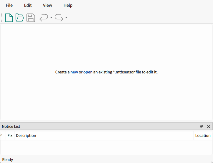
When opened this way, the Sensor Designer tool GUI opens blank without any information.
Quick start
This section provides a simple workflow for how to use the Sensor Designer tool.
-
Create a new or open an existing sensor configuration to edit it.
-
Edit the configuration.
-
Generate a Liquid Level or Button sensor drawing.
-
Save the configuration.
-
Click the Generate DXF button to generate a *.dxf file to the specified directory. Then, import the file to the CAD software.
GUI description
Menus
-
File
-
New - Creates a new file with new configuration.
-
Open… - Opens a specified *.mtbsensor configuration file. The current configuration file, if any, will be closed. If there are unsaved changes, a dialog opens asking to save or not.
-
Close - Closes the current configuration file.
-
Save - Saves the current configuration file.
-
Save As… - Saves the existing file under a different name.
-
Open in System Explorer - This opens your computer’s file explorer tool to the folder that contains the *.mtbsensor configuration file.
-
Recent files - Shows recent files that you can open directly.
-
Exit - Closes the tool. You will be prompted to save any pending changes.
-
-
Edit
-
Undo - Undoes the last action or sequence of actions.
-
Redo - Redoes the last undone action or sequence of undone actions.
-
-
View
-
Notice List - Hides or shows the Notice List pane. The pane displays by default.
-
Toolbar - Hides or shows the Toolbar.
-
Reset View - Resets the view to the default.
-
-
Help
-
View Help - Opens this document.
-
About Sensor Designer tool - Opens the About box for version information, with links to open https://www.infineon.com and the current session log files of the application.
-
Toolbar
The toolbar contains common commands from the File and Edit menus. Use the check box under the View menu to show or hide the toolbar.

Sensor tabs
The Liquid Level tab and Button tab sensor tabs represent the relevant sensor configuration. A tab contains a set of parameters to configure the settings of a sensor drawing pattern and generate it to the *.dxf file.
The tab name is provided as the default name for the generated *.dxf file.
![]()
Select sensor
To create new tab configuration, click New on the File menu. It will display the "Select sensor" dialog.
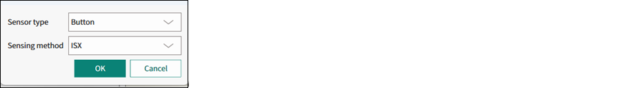
- Sensor type - Liquid Level or Button .
- Sensing method - CSD for Liquid Level , ISX for Button .
Move actions
-
To add a tab for a new level, click the green button to display the "Select sensor" dialog.
-
To remove a tab, click the red button.
-
To rename the sensor, double-click its name.
-
To change the tabs order, left-click a tab name and drag it to the preferred position.
Liquid Level tab
The Liquid Level tab is used to design a liquid level sensor for the preferred application requirements and generate a *.dxf file.
Commands
-
Restore Defaults - Restores parameters values on the current tab to their default values.
-
Copy All - Click this button to copy the list of input and output parameters to the system clipboard as plain text.
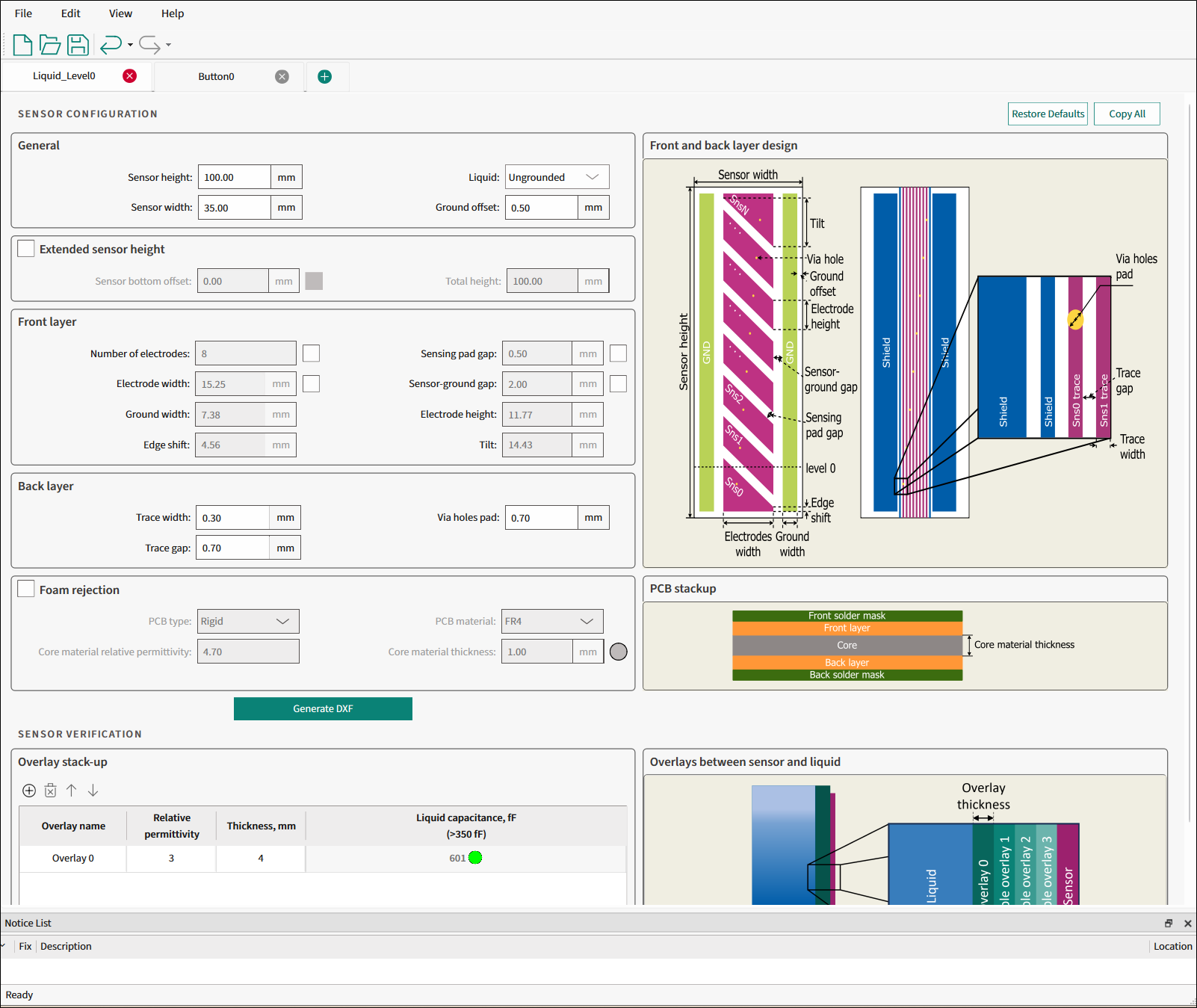
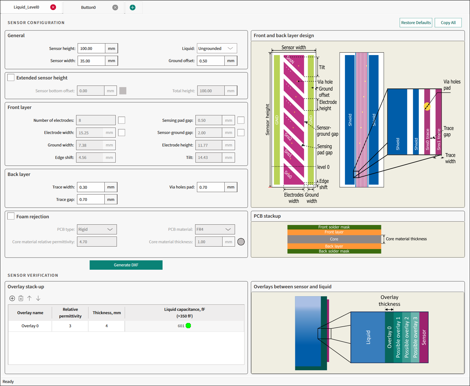
Sensor configuration
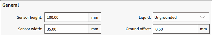
General
-
Sensor height - The height (mm) of the sensor measurable stack-up. The range – 30.00-422.5, default – 100.00.
-
Sensor width - The width (mm) of the entire sensor stack-up. The range – 20.00-60.00, default – 35.00.
-
Liquid - Select whether the liquid is Ungrounded or Grounded. Default – Ungrounded.
-
Ground offset - The spacing gap (mm)between the outer ground traces and the edge of the sensor area. The range – 0.5-15, default – 0.50.
Extended sensor height
The extended sensor height improves the accuracy near the bottom of calculated levels.

-
Sensor bottom offset - The height of the measurement offset. The range – 0-.99.99, default – 12.00.
-
Total height - Read-only. The total height of the sensor.
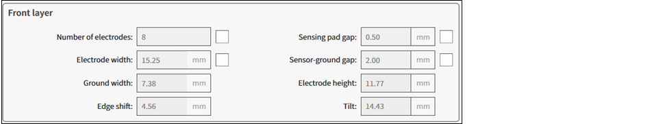
Front layer
Select the relevant check box to use the parameter as an input parameter.
-
Number of electrodes - The total number of electrodes. The range – 3-32.
-
Electrode width - The horizontal width (mm)of each electrode. The range – 1-59.99.
-
Ground width - Read-only. The width (mm) of the ground traces.
-
Edge shift - Read-only. The edge shift (mm) area on the top and bottom electrodes. This value can be negative.
-
Sensing pad gap - The space (mm) between the electrodes. The range – 0.1-10.
-
Sensor-ground gap - The horizontal space (mm) between the electrodes and neighboring ground traces. The range – 0.1-10.
-
Electrode height - Read-only. The height (mm) of an electrode when measured at a single point on the horizontal axis.
-
Tilt - Read-only. The distance (mm) between the highest and lowest points of the tilted edge of an electrode.
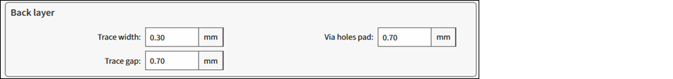
Back layer
-
Trace width - The width (mm) of the trace, which connects some segment of the Liquid Level sensor with the connector. The range – 0.1-10, default – 0.30.
-
Trace gap - The distance (mm) between adjacent trace widths. The range – 0.1-10, default – 0.70.
-
Via holes pad - The diameter (mm) of through-hole pads for each sensor between the front and back layer. The range – 0.1-10, default – 0.70.
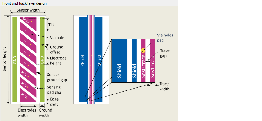
Illustration of front and back layer design parameters
Foam rejection
Enables the foam rejection analysis for the selected sensor design.
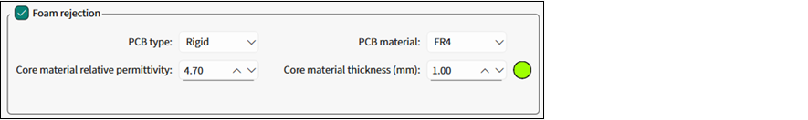
-
PCB type - The PCB technology used for the sensor: Rigid, Flex, Other.
-
**Core material relative permittivity ** - The relative permittivity of the PCB core material. The range – 2-10, default – 4.70.
-
PCB material - The PCB base material used for the sensor. Available: FR4, FR5, Getek, Rogers4350, Teflon, Polyimide, Polyester, Polyethylene Naphthalate, Liquid Crystal Polymer, Arylon.
-
Core material thickness - The thickness (mm) of the PCB core material between the conductive layers. The range – 0.01-5, default – 1.00.
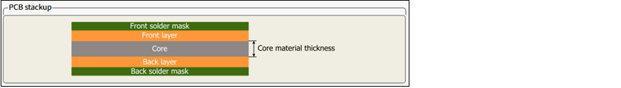
Illustration of PCB stackup
Generate DXF
Click this button to generate a *.dxf file of the calculated liquid level sensor to a specified file location.
![]()
Sensor verification
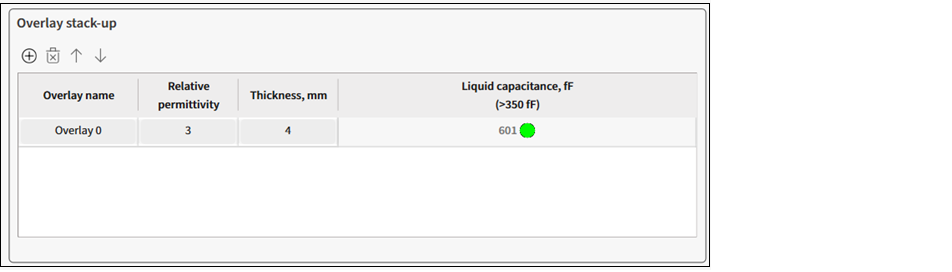
Overlay stack-up
Toolbar
- To add an overlay, click the "plus" icon.
- To remove an overlay, click the "cross" icon.
- To move an overlay up/down, use the arrows.
Verification parameters table
-
Overlay name - The name of an overlay stack-up.
-
Relative permittivity - Relative permittivity of the overlayer/stack-up material.
-
Thickness, mm - The thickness of an overlay stack-up.
-
Liquid capacitance, fF (>350fF) - The guarding value of calculated sensor capacitance depending on the sensor design and amount of added liquid. In short, the sensor capacitance caused by added liquid. This parameter must exceed 350fF. The sign in the executive button and a message in the Notice List will be displayed to indicated inefficient design.
When the value is below 350fF, you can still generate a *.dxf file but the sensor may have low performance.
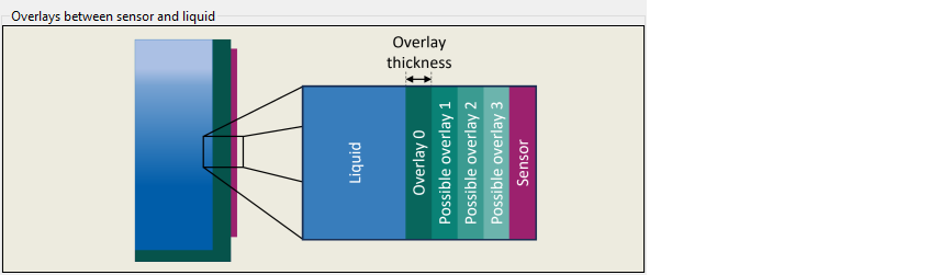
Illustration of overlays between sensor and liquid
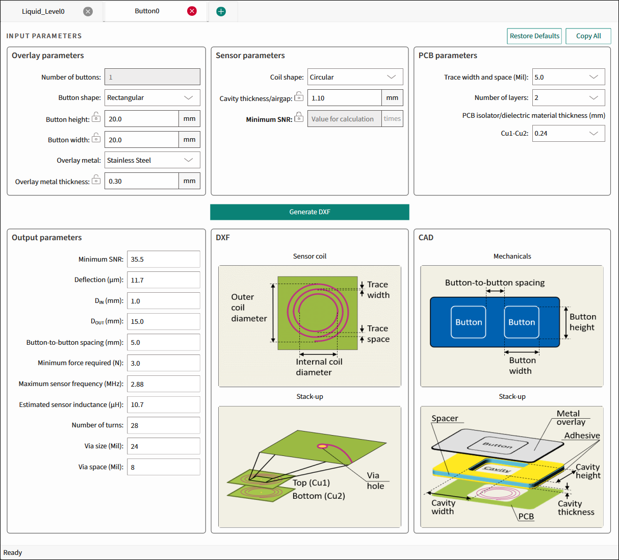
Button tab
The Button tab is used to design an inductive sensing coil and its parameters for the preferred application requirements and generate a *.dxf file.
Commands
-
Restore Defaults - Restores parameters values on the current tab to their default values.
-
Copy All - Click this button to copy the list of input and output parameters to the system clipboard as plain text.
Input parameters
The Input parameters include Overlay, Sensor, and PCB parameters.
The first output parameter will always be the same parameter, which is locked ![]() in the Input parameters section. Lock the relevant parameter by double-clicking its unlocked icon
in the Input parameters section. Lock the relevant parameter by double-clicking its unlocked icon ![]() . Only one parameter can be locked at a time.
. Only one parameter can be locked at a time.
Overlay parameters
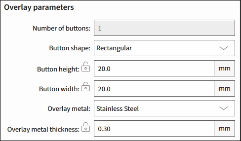
-
Number of buttons - The number of buttons in the specified widget. Default – 1.
-
Button shape - Circular.
-
Button diameter (mm) - The range is 8-28, default – 20.
-
Overlay metal 1 – Stainless Steel, Aluminum. Default – Stainless Steel.
-
Overlay metal thickness (mm) - The thickness of the specified overlay. The range is 0.2-0.5, default – 0.30.
-
Stainless Steel – The range is 0.2-0.5, default – 0.30.
-
Aluminum – The range is 0.25-0.5, default – 0.30.
-
Sensor parameters
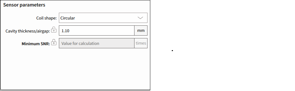
-
Coil shape - Circular.
-
Cavity thickness/airgap (mm) - The gap between the overlay and the sensor coil. The range is 0.3-7. Default – 1.10.
-
Minimum SNR (times) - The minimum SNR required for the sensor optimum performance. The range is 1-40.
PCB parameters
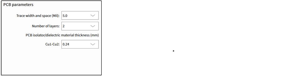
-
Trace width and space (Mil) - The minimum sensor PCB trace width for generating output parameters. Select from: 3.5, 4.0, 5.0, or 7.0. Default – 5.
-
Number of layers - The number of Cu layers. Select from: 1, 2 or 4. Default – 2.
-
PCB isolator/dielectric material thickness (mm) - Enabled for more than 1 layer. The thickness of PCB Isolator or dielectric material used between Cu layers.
- For 2 layers, Cu1-Cu2, select from: 0.24, 0.4, 1.0, 1.2. Default – 0.24.
- For 4 layers, the spaces between the layers are fixed: 0.24 – 1.0 – 0.24.
Generate DXF
Click this button to generate a *.dxf file of the calculated liquid level sensor to a specified file location.
![]()
This button is disabled if the calculated value is beyond the allowed range and the first field of the Output parameters indicates that.
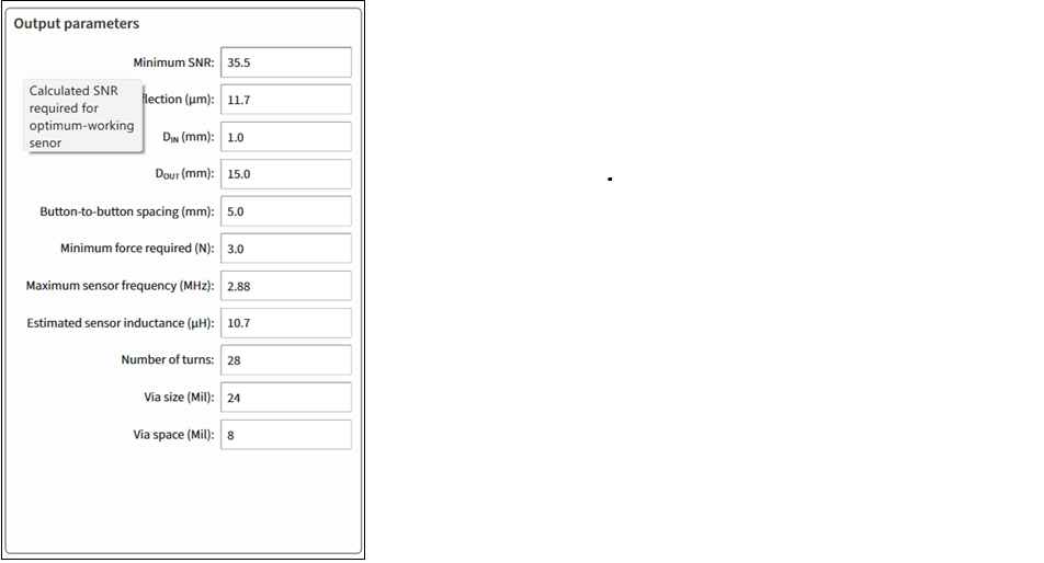
Output parameters
The first output parameter will always be the same parameter, which is locked ![]() in the Input parameters section. Lock the relevant parameter by double-clicking its unlock
in the Input parameters section. Lock the relevant parameter by double-clicking its unlock ![]() icon .
icon .
Only one parameter can be locked at a time.
-
Button height and width, Button diameter, Minimum SNR (times), Overlay metal thickness, and Cavity thickness/airgap - The calculated value of a specified parameter.
-
Deflection (µm) - The overlay deflection for the minimum force applied to trigger the sensor to achieve the calculated or specified SNR.
-
D IN ** (mm)** - The sensor-coil inner diameter/diagonal.
-
D OUT (mm) - The sensor-coil outer diameter/diagonal. Always – 75 % of the referred button size.
-
Button-to-button spacing (mm) - The minimum spacing between buttons.
-
Minimum force required (N) - The minimum sensor-activation force to achieve the calculated or specified SNR. Always – 3 N.
-
Maximum sensor frequency (MHz) - The maximum sensor-drive frequency.
-
Estimated sensor inductance (µH) - The estimated effective sensor coil inductance. The estimate is based on the number of coil turns, trace width, PCB layers, PCB layers spacing.
-
Number of turns - The number of coil turns per each layer.
-
Via size (Mil) - The diameter of the through-hole pad in the multi-layer PCB.
-
Via space (Mil) - Spacing between through-hole pads and coil wire in the multi-layer PCB.
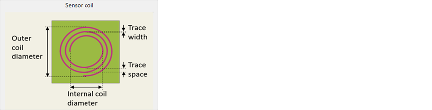
Illustration of DXF design
Displays the calculated structure of a designed sensor array.
Sensor coil
The illustrative image of a sensor coil.
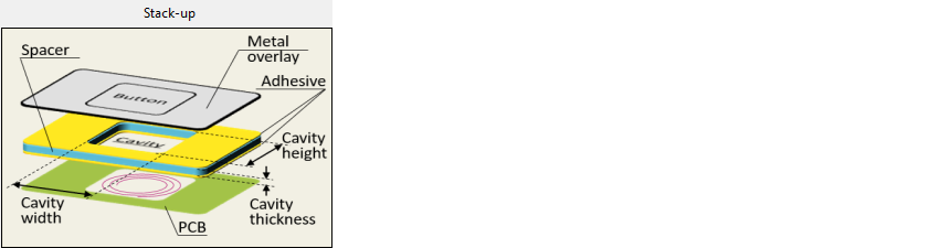
Stack-up
The illustrative image of a DXF Stack-up.
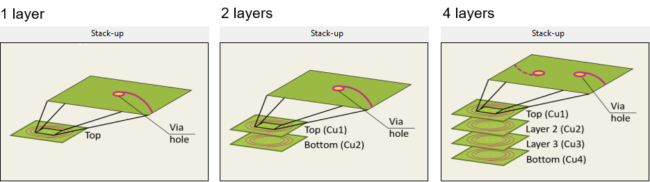
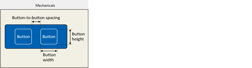
Illustration of CAD design
Displays the calculated mechanical structure of a designed button.
Mechanicals
The illustrative image of the buttons' placement.
Stack-up
The illustrative image of the CAD stack-up.
Version changes
| Version | Change descriptions |
|---|---|
| 1.0 | New tool. |
| 1.10 | Improved ISX Button tab design and calculation Unified Liquid Level and ISX Button tabs behavior |
| 1.20 | Updated Liquid Level sensor dimensions. |
| Updated GUI style. | |
| 1.21 | Restricted Coil Shape to the Circular option for ISX Button sensors. |
| Added core material estimation for the foam rejection feature. | |
| 1.30 | Added the extended sensor height feature. |
Revision history
| Revision | Date | Description |
|---|---|---|
| ** | 2025-02-12 | New document. |
| *A | 2025-03-04 | Updated to version 1.10. |
| *B | 2025-10-06 | Updated to version 1.20. |
| *C | 2026-04-14 | Updated to version 1.21. |
| *D | 2026-05-22 | Updated to version 1.30. |
Footnotes
-
Titanium, Copper – not supported for this release. ↩