AN2020-04 HybridPACK 2: General information and mounting instruction
About this document
Scope and purpose
This application note provides mounting instructions for HybridPACK™ 2 module with recommendations how to screw the module, assemble the PCB, and mount the module onto the heatsink.
Intended audience
Engineers and operators involved in developing a system using the HybridPACK™ 2 module.
Introduction
As a result of the operation of high-power modules, power losses must be dissipated through a heatsink in such a way that the maximum permissible temperature specified in the datasheet cannot be exceeded. The mounting process of power modules is therefore vital because it affects the module’s thermal performance and its reliability, which is critical for automotive applications.
Ensure that the ground straps should be worn while working with the components and that the ESD safety instructions must be followed at all times, since IGBT modules are electronic-static sensitive components. In addition, the maximum permissible values set out in the product datasheet and application notes are absolute limits which, in general, cannot be exceeded for a short period of time, as this may lead to the destruction of the component. In addition, this application note does not cover all types of applications or conditions. As a result, the application note cannot replace a detailed assessment and examination of the suitability of the targeted applications carried out by you or your technical divisions. In any event, the application note must not become part of any supplier-agreed warranty, unless the supply agreement determines otherwise in writing.
Proposal for designing a driver board
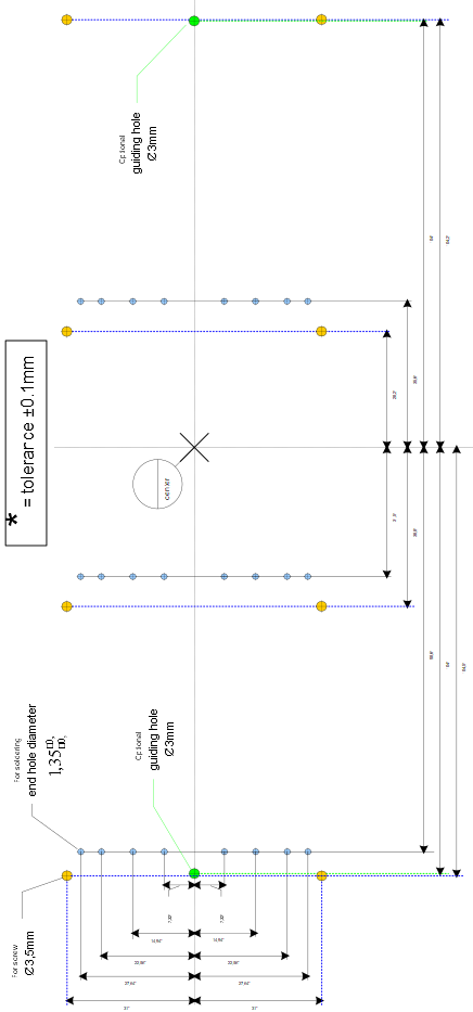
On the basis of the HybridPACK™ 2 dimensions, a proposal for designing a driver board can be presented (see Figure 1). The diameter of the end-hole of the module solder pin connection should be
.
The geometry and footprints of the connector must be taken into account when designing a driver board that uses connectors (for example, JST connector type "09HVD6B-EMGF-NR").
Figure 1. Proposal for designing a driver board for HybridPACK™ 2 module
Mounting a driver board onto the module
The driver board can be mounted in two ways: through connectors (strongly recommended) or by direct soldering on the top of the module.
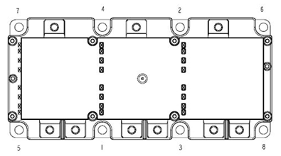
If a driver board or module adapter board (PCB) is soldered directly on top of a module, the contact joints (solder connections) between the PCB and the auxiliary contacts of the module must be mechanically relieved as much as possible. The contact points were relieved by mounting the PCB directly onto the module at the eight mounting stand-offs (Figure 2) using self-tapping (thread forming) screws or a similar material. The length of the used self-tapping screws depends on the PCB thickness. Example: For mounting a PCB with 1.6 mm thickness, a self-trapping screw with 3 mm diameter and 10 mm length, such as the Delta PT 30 × 10 from EJOT, should be used.
Figure 2. PCB mounting stand-off of HybridPACK™ 2 module
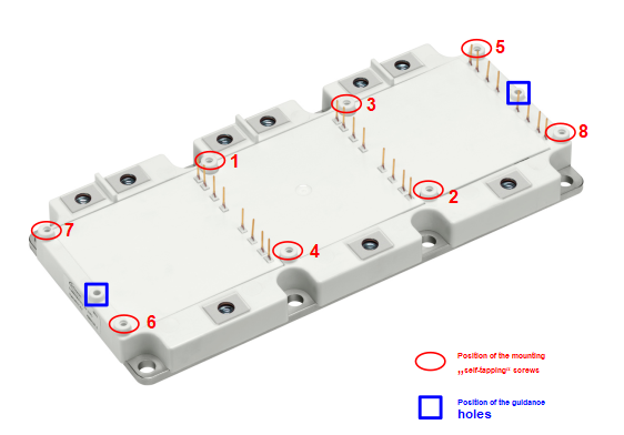
The screws should be mounted in the sequence shown in Figure 2. The initial 1.5 mm of the mounting stand-off serves only as guidance and cannot be used with any force. The thread in the plastic will form when the screws are driven. In addition to manually inserting the screws into the mounting stand-offs, an electronically controlled or at least slowly turning electric screwdriver (≤300 rpm) is preferred (due to the lack of accuracy, pneumatic screwdriver is not recommended). The maximum applied Torque Mmax is 0.9 Nm ±10%. If the thickness and weight of the driver PCB are taken into account, the effective length of the screw thread entering the mounting stand-off should be of a minimum length of lmin ≥ 6 mm and a maximum length of lmax ≤ 9 mm.
The HybridPACK™ 2 offers two guidance holes marked in blue, as shown in Figure 2. These guidance holes provide assistance when mounting the PCB on the module and allow automated assembly.
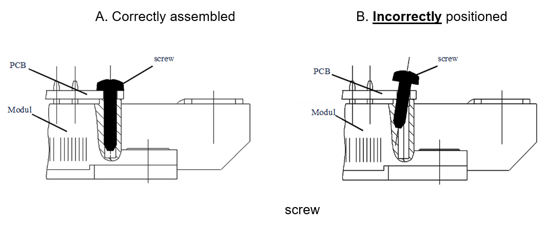
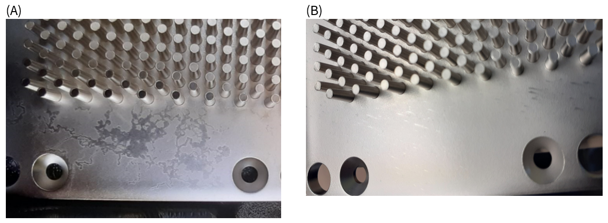
To avoid damage or breakage of the stand-off, a screw must be inserted straight into the stand-off during assembly (Figure 3).
Figure 3. (A) Correctly assembled screw into the mounting stand-off and (B) incorrectly positioned screw into the mounting stand-off
The recommended screws and torque are based on laboratory tests. Depending on the screws and tools used, it may be necessary to adapt the assembly process accordingly.
The solder process (manual soldering, selective soldering, or wave soldering) may begin after the PCB is mounted. The mechanical strain on the solder points can be minimized when adhering to this sequence of assembly.
During the entire soldering process, care should be taken not to overheat the plastic case and hence deform it, if the soldering temperature is too high or the process time is too long at the auxiliary pin.
According to IEC68 Section 2, a maximum solder temperature of T = 260°C for a maximum process time of tmax ≤ 10 s must be observed during the solder process.
Instead of direct soldering, the PCB could also be attached to the module using connectors. This electrical connection between the PCB and module can use any connector designed for a pin cross-section of 0.64 × 0.64 mm, especially JST connector type “09HVD6B-EMGF-NR”. The module auxiliary terminals (pin connectors) are designed especially for fitting to the JST connectors (surface and dimensions).
Figure 4. Technical drawing of the HybridPACK™ 2 auxiliary terminals (pin connectors)
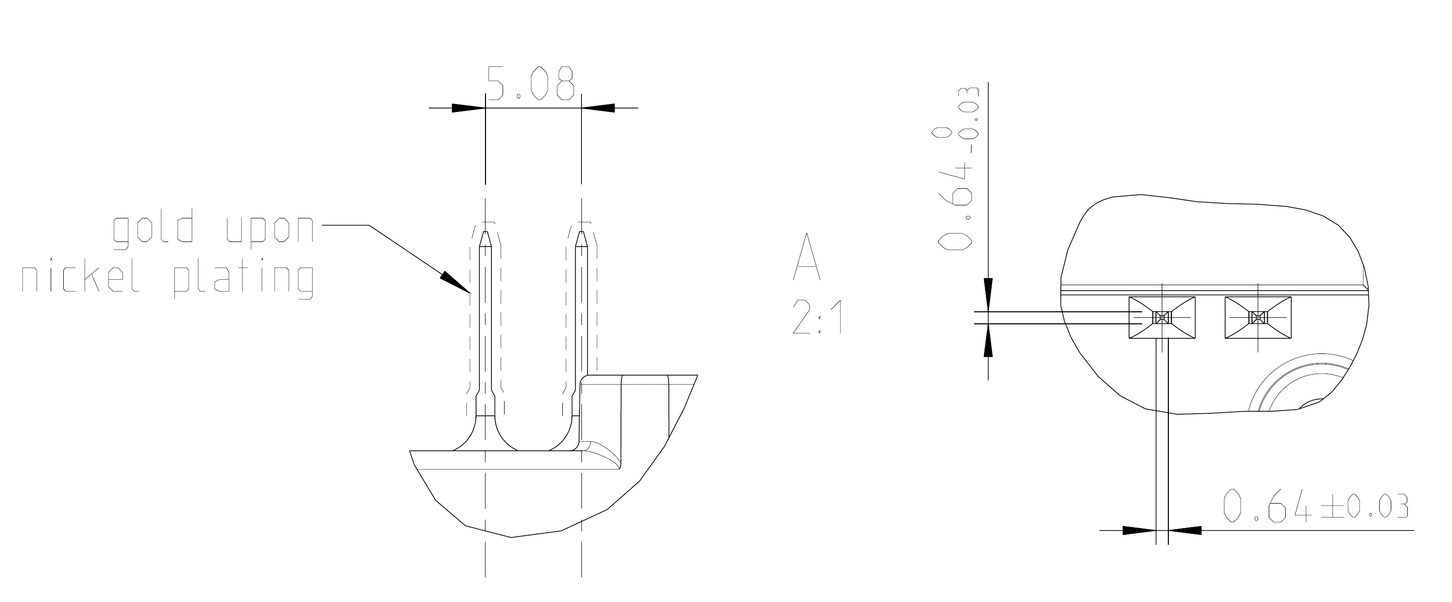
Figure 4 shows the dimensions and structure of the auxiliary terminals. Due to the specific requirements of the JST connector, the auxiliary terminals have the following properties:
Auxiliary terminals are made of 63% International Annealed Copper Standard (IACS) copper material
Auxiliary terminals have a gold (Au) surface and nickel (Ni) under plating
Tensile strength of the auxiliary terminals must be equal to or greater than 530 MPa
Application of the liquid cooling system
In order to avoid exceeding the maximum permissible temperature specified in the datasheet during switching (Tvj_op = 150°C) in operation, the power loss occurring in the module must be dissipated. Therefore, designing a cooling system/heatsink is of great importance to achieve good performance.
HybridPACK™ 2 differs from other power modules because of its pin-fin array on the baseplate, which makes liquid cooling very effective in terms of thermal performance. The baseplate is made of copper (Cu) with nickel (Ni) plating. The pin-fin structure is suitable for cooling fluids, such as water/ethylenglycol mixtures.
The pin-fin array is placed on the module baseplate to maximize the heat exchange effect, as shown in Figure 5. To confirm the waterproofness of the fluid cooling system, an O-ring sealing type 202 × 64.2 × 3 mm (such as,part number DRYD001590E768U from Trelleborg company) should be utilized on the heatsink. Such an O-ring is held in a groove, which surrounds the tray that holds the pin fin array. This groove should be restricted to the region on the heatsink that corresponds to the region around the pin-fin structure, as shown in Figure 5 and Figure 6. There should be no contamination, scratches, or other baseplate damage in this region.
Figure 5. Technical drawing of HybridPACK™ 2 bottom side
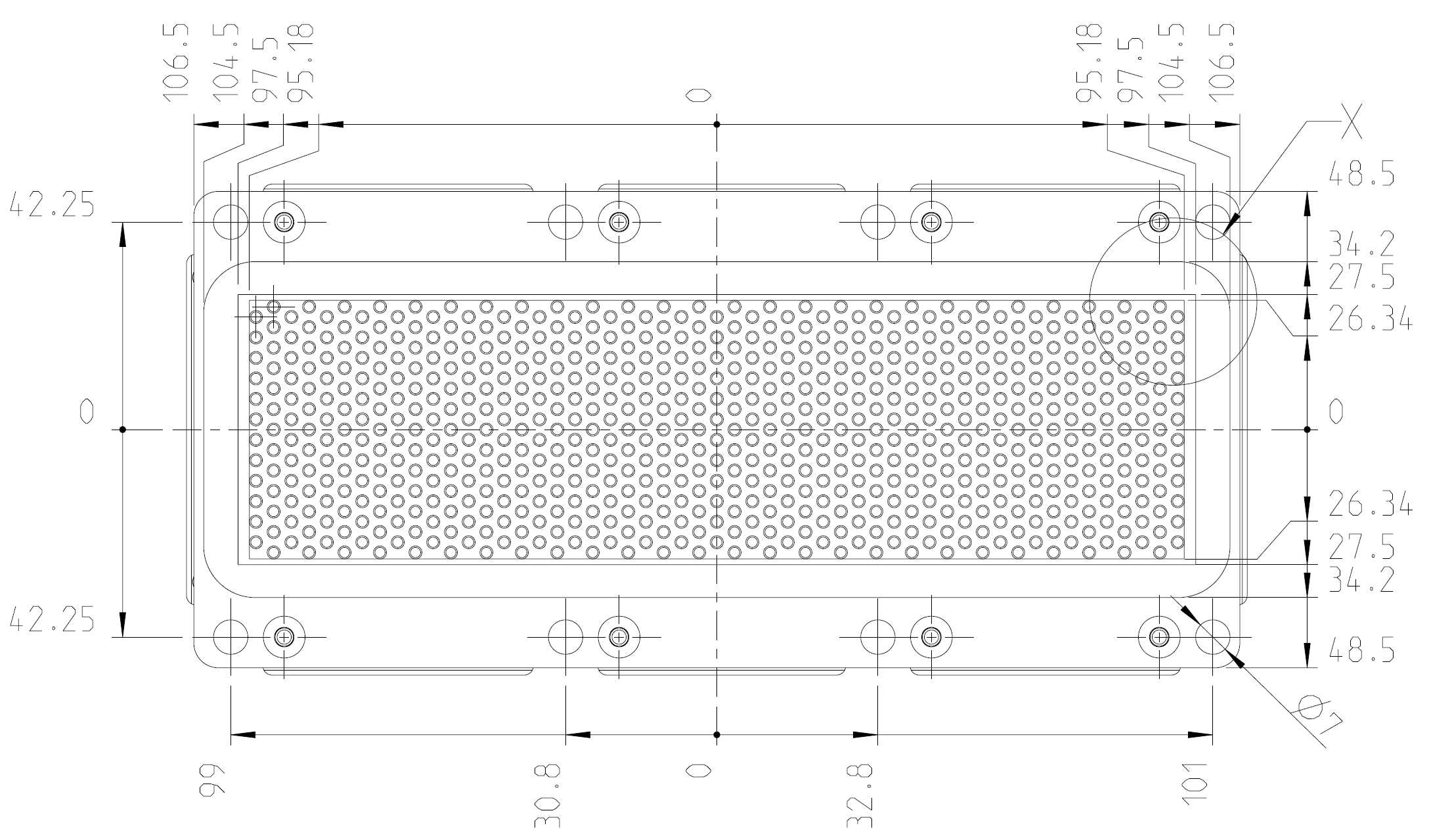
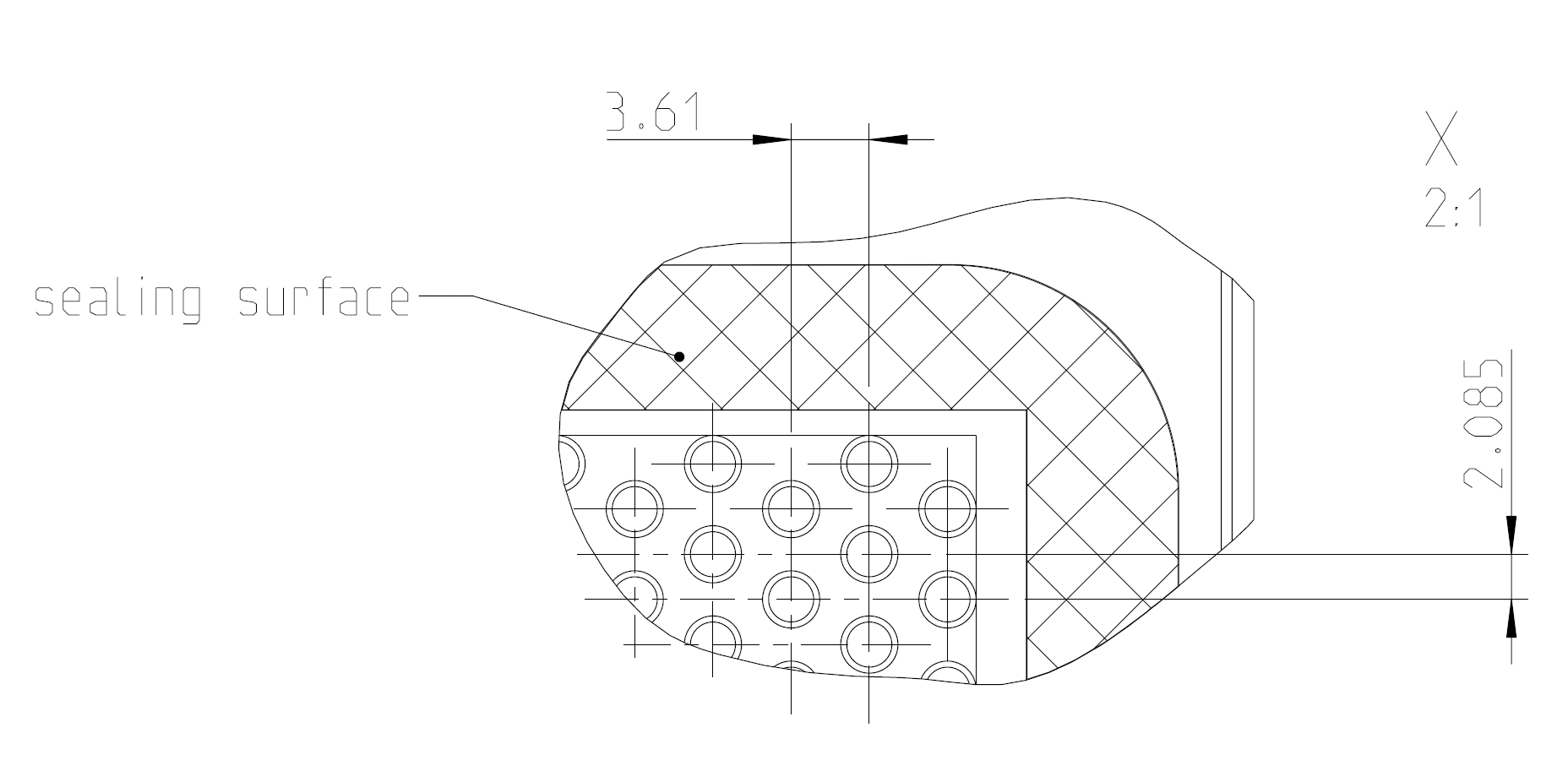
Figure 6. “X”-section detail drawing of the HybridPACK™ 2 bottom side. The sealing surface corresponds to the O-ring holding groove.
The dimensions of the tray holding the pin-fin array with specified tolerances are depicted in Figure 7A.
The contact surfaces between the baseplate of the module and the surface of the heatsink must be free of any degradation or contamination and must be cleaned with a fresh, lint-free cloth.
The contact surface of the heatsink should not exceed the following values referenced to a length of L = 100 mm:
Surface flatness: ≤50 µm
Surface roughness Rz: ≤10 µm
Surface roughness at the sealing surface Ra: ≤1.6 µm
The heatsink must be sufficiently stiff for assembly and subsequent transport in order not to exert any additional strain or pulling forces on the baseplate of the modules. During the entire assembly process, the heatsink must be twist free.
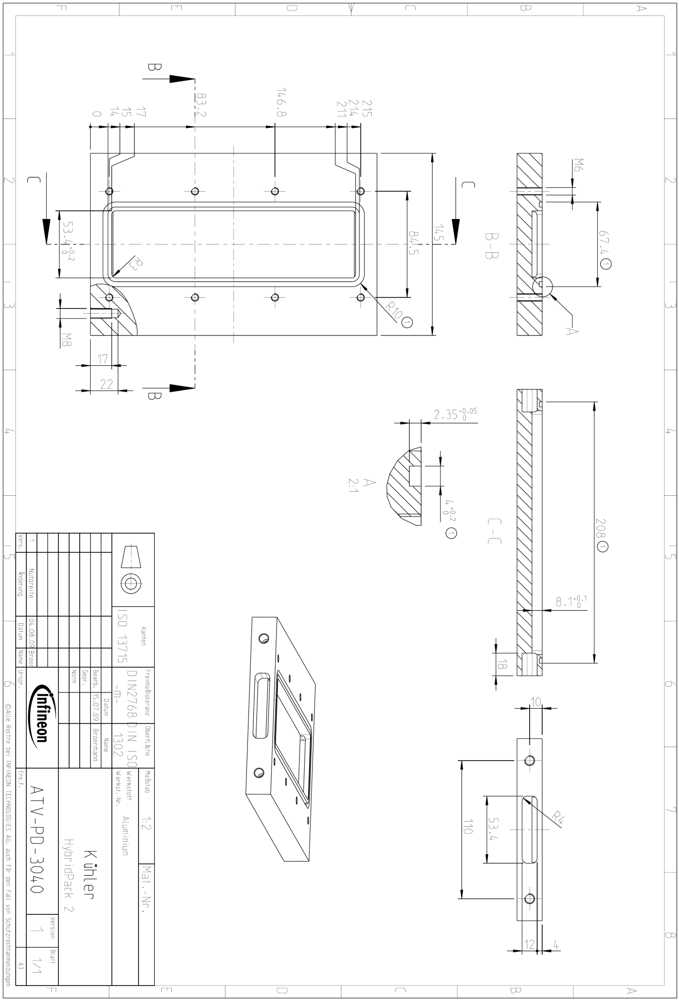
An example of the fluid cooling system design can be found in the datasheet of HybridPACK™ 2 and Figure 7. This cooling system from Trelleborg with part number DRYD001590E768U is designed for O-ring sealing.
Figure 7. A design example of fluid cooling system
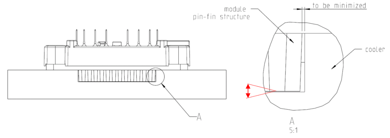
A cross-sectional view of the HybridPACK™ 2 module and the heatsink is presented in Figure 8. This cross section shows that certain distances must be minimized so that the cooling fluid does not bypass the pin-fin structure. One of the critical places is the border region between the pin-fin structure and the heatsink wall, as shown in the “A” area (represented in Figure 8 with black color). If the distance between the pin-fin structure and the heatsink is too large, it will provide an unwanted bypass for the fluid. This will eventually decrease the cooling performance. The second critical path is the gap between the pin-fin structure and the bottom of the heatsink (represented in Figure 8 with red color). This gap should also be minimized.
Figure 8. A cross-sectional view of HybridPACK™ 2 and the heatsink. Certain distances should be minimized within the shown area “A” to obtain optimized cooling performance.
Baseplate surface
The baseplate surface typically has a so-called “marbling” or “white spots” structure. This structure can be observed after galvanic nickel cleaning of the baseplates. The roughness of the baseplate, the chemical structure, and the thickness of the Ni layer do not differ from those of baseplates where this structure is not visible by the naked eye. The appearance shown in Figure 9 is a normal appearance and does not constitute an objection, since it does not have an impact on product performance or quality.
Figure 9. Typical appearance of power module baseplate surface with a “marbling” or “white spots” structure
Screws to mount the module to the heatsink
The following screws are recommended for mounting the module: DIN M6 screws that comply at least with class 6.8 (for example, according to DIN 912 (ISO4762), ISO 7380, DIN 6912, and DIN 7984) in combination with a suitable dented edge washer and spring washer (for example, according to DIN 433 or DIN 125) or the combination of both the “dented edge washer.” The diameter of the used washer is 10 mm.
The clearance and creepage distances specified in the HybridPACK™ 2 datasheets are the shortest clearance and creepage distances for unassembled and disconnected modules.
When selecting suitable M6 screws, washers, and spring washers for mounting the module, it is recommended that the clearance and creepage distance between the power terminal and the nearest bolt head or washer should be considered during the development phase.
Mounting the module to the heatsink
The clamping force of the module resulting from the assembly process to the heatsink depends on the torque applied and the heatsink material. The following torque values specified in the datasheet result from steel screws in aluminium heatsinks with a dry M6 thread and their typical friction factors of µG = 0.2~0.25 (µG = friction coefficient thread in heatsink):
In order to ensure good thermal contact with the heatsink, it is recommended to tighten the eight M6 fastening screws using a washer (according to DIN 433) and a spring washer (according to DIN 127).
Place the module onto the heatsink and fix it with two screws
Fix the screws with 0.5 Nm (hand tight crosswise) in the sequence shown in Figure 10
Tighten the screws with 3–6 Nm in the same sequence (crosswise)
Figure 10. Tightening sequence to mount the module
Connecting the bus bars to the power terminals
In order to keep the switching overvoltage as low as possible by minimizing stray inductance, the DC power side should be connected with a laminated DC bus bar. According to the RBSOA data in the datasheet, compliance with the maximum permissible voltage at the power terminals and at the IGBT chip must be guaranteed.
For the connection of power terminals, DIN M6 screws which comply at least with class 6.8 are required in combination with a suitable washer and spring washer or a complete combination screw. These should be tightened with a recommended torque of Mmin = 2.5 Nm to Mmax = 5.0 Nm.
When selecting the length of the screws, the thickness of the connecting parts must be subtracted from the total length of the screws. The actual length of engagement into the module thread must not exceed the maximum specified depth of 10 mm.
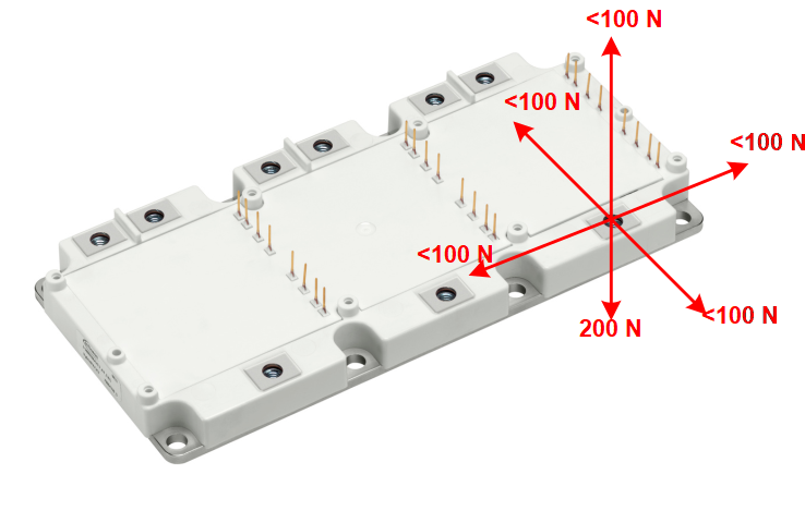
As shown in Figure 11, the connected parts must be mounted to the power terminals in such a way that the specified static forces are not exceeded during assembly or later in operation.
Figure 11. Maximum permissible static pull-and-push forces at the power terminal of HybridPACK™ 2
Connecting the power terminals with ideal strain relief
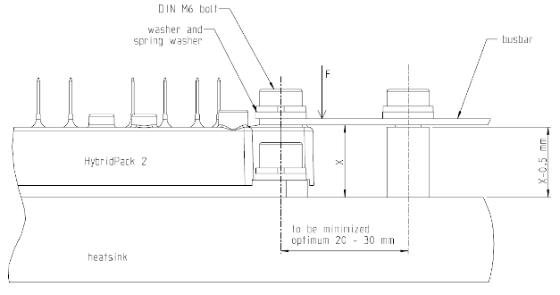
A recommended assembly schematic is shown in Figure 12, in which a bus bar is connected to the power terminals in such a way that only a low force is applied to them, even during shock or vibration conditions, to provide the best possible strain relief. The power terminals are able to withstand the force F best in the direction from the terminal to the baseplate. Force in other directions must be avoided. This must also be taken into account in the tolerance of the bus bar.
Figure 12. Concept drawing of HybridPACK™ 2 assembly with ideal strain relief
Storage and transport
The module can be stored at the temperature limits specified in the datasheet, but it is not recommended.
According to IEC60721-3-1, class 1K2, storage conditions should be ensured for a maximum storage time of 2 years.
Maximum air temperature: Tmaxair = +40°C
Minimum air temperature: Tminair = +5°C
Maximum relative humidity: 85%
Minimum relative humidity: 5%
Condensation: not permissible
Precipitation: not permissible
Icing: not permissible
The HybridPACK™ 2 modules do not require pre-drying of the case prior to the soldering process, which is recommended for moulded discrete components (for example, microcontrollers, TO-cases, etc.).
Data matrix (DMX) part marking
Infineon Technologies, as a part of the electronic industry, has made a significant contribution by using a data matrix part marking to change the way HybridPACK™ products are traced, both in the manufacturing process and throughout the life cycle of the product or component. Total traceability means significant improvements in process and quality control.
Data Matrix is a two-dimensional code which is machine readable with conventional 2D reader or scanner. The readers are capable of reading low contrast marks, damaged codes and even codes on severely compromised surfaces. On the picture below the side view of HybridPACK™ 2 is depicted. From this picture the marking of the module can be seen together with the Data Matrix (DMX) - Code, Date Code and the Serial Nr.
Data matrix is a two-dimensional code that is machine readable with a conventional 2D reader or scanner. Readers are able to read low-contrast marks, damaged codes, and even codes on highly damaged surfaces. A side view of HybridPACK™ 2 is depicted Figure 13. The marking of the module, together with the data matrix (DMX)-Code, Date Code, and Serial Nr, can be seen in this figure.
Figure 13. HybridPACK™ 2 figure (side view)
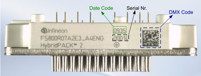
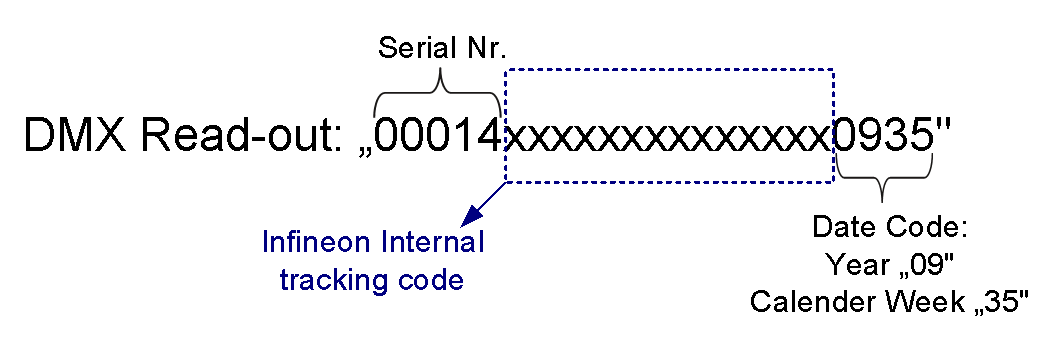
When the DMX-Code of the module depicted in Figure 13 has been read out with a conventional scanner, the following characters will be displayed:
Figure 14. HybridPACK™ 2 DMX Read-out
Revision history
| Document version | Date of release | Description of changes |
|---|---|---|
| 2.0 | 2010-08-10 |
|
| 2.1 | 2020-04 |
|
| 2.2 | 2023-12-07 |
|