Creating a schematic
Schematics are created in the Workspace view and populated in the work area.
Before you begin
The tutorial project must have been created, as described in Creating a project. It must contain an empty schematic.
About this task
In this example, you will create a simple low-pass filter.
Procedure
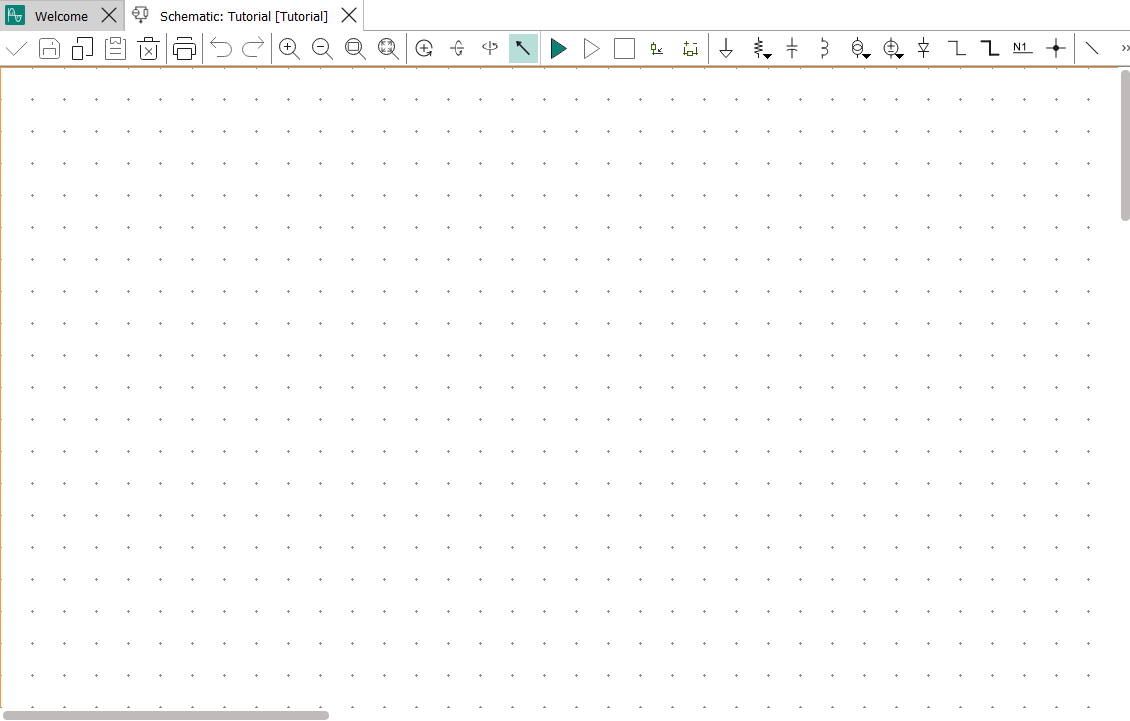
- If the empty schematic is not already open, open it by double-clicking its file
in the Workspace view.

The schematic is displayed in the work area.
- Place the voltage source.
We are using a sinusoidal voltage source, which is a basic component.
The following steps show how to place such components from the model libraries, which works in the same way for more complicated components. Basic components can also be placed using the toolbar icons in a schematic view. Except for how the desired component is chosen, the procedure is the same as described here.
- Drag the entry Sinusoidal from the library to
the work area.
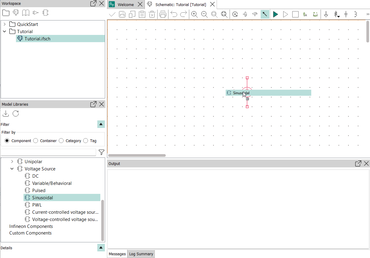
Instead of dragging the component, you can also double-click it in the library.
The cursor changes its form
 to indicate that you
can now place sinusoidal voltage sources.
to indicate that you
can now place sinusoidal voltage sources.
The schematic now contains a sinusoidal voltage source.
- Drag the entry Sinusoidal from the library to
the work area.
- Zoom in to get a better view of the component.
To do so, click the Zoom In
 tool until the voltage
source symbol is large enough or click the Zoom Region
tool until the voltage
source symbol is large enough or click the Zoom Region  tool and drag a conveniently sized rectangle around the area on which you
want to zoom in.
tool and drag a conveniently sized rectangle around the area on which you
want to zoom in.You should now be able to clearly see the symbol in the schematic.
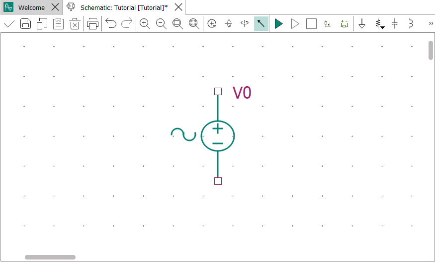
The dots in the background indicate the grid that can assist you in correctly placing and aligning components.
- Edit the properties of the voltage source to fit the schematics’
requirements.
- Choose the Select Mode tool
 and double-click the
voltage source.
and double-click the
voltage source.Alternatively, you can also select the voltage source and press Q or right-click it and choose Properties.
The Properties dialog opens.
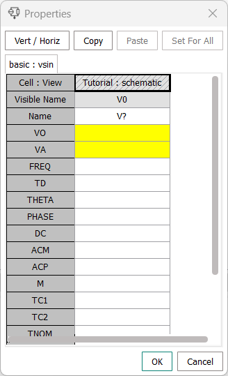
The dialog lists all available parameters of the selected component. Parameters that are mandatory are highlighted in yellow. Brief explanations of the parameters are available by hovering the mouse over the parameter name.
- Enter the following values: VO 0, VA 1, FREQ 1MEG, TD
0. Click OK.
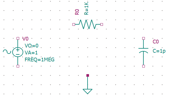
The most important of the specified values are displayed beside the voltage source.

- Choose the Select Mode tool
- Select the resistor, right-click it, and choose Rotate from the context
menu.
Your schematic now looks similar to this:
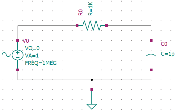
- Connect the components with wires.
- Choose the wire tool
 .
.
The schematic now looks like this:
- Choose the wire tool
- Label the wires to the resistor.
- Choose the wire labeling tool
 .
.The Wire Name dialog opens:

- Choose again, enter OUT as the wire name, and
click the wire from the resistor to the capacitor.The wire is labeled “OUT”.
The wires are now labeled:
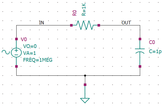
These labels can be referenced when setting up the simulation.
- Choose the wire labeling tool
Results
You have created a schematic for a simple low-pass filter the operation of which can be simulated in InfineonSpice.
What to do next
Set up. the simulation as described in Setting up a simulation.