Setting up a simulation
The parameters with which a simulation is performed are configured in the Simulation Environment view.
About this task
Setting up a simulation with the appropriate parameters ensures that it will produce meaningful results.
Before you begin
You need a schematic that you can simulate. We recommend using the schematic that you have created in Creating a schematic. If you use a different schematic, the process is the same, but some of the settings may not be available or may need to be different.
Procedure
- If the Simulation Environment view is not open, choose View > Simulation Environment to open it.
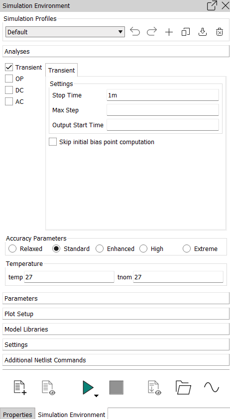
- Create a new simulation profile.
Simulation profiles collect the settings with which a simulation is run. By storing settings in a profile, you can quickly recall them for future simulations in the same project or in others.
- In the toolbar of the Simulation
Environment view, click
 .
.The toolbar is overlaid with a text entry field.
The Simulation Environment view displays the new, empty profile TutorialProfile. Any changes you now make to the settings in the view change this profile but not others.
- In the toolbar of the Simulation
Environment view, click
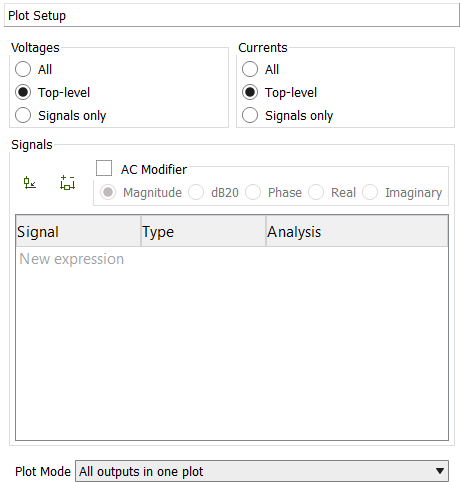
- Specify the desired outputs to be measured.
Outputs are the signals that are plotted in the Waveform Viewer after the simulation. You can add more outputs after running the simulation, but specifying them upfront helps you see the important results immediately.
For this example, the output voltage and the current through the capacitor of the low-pass filter will be plotted.
- Click the Plot Setup section of the
Simulation Environment view.
The section expands.
- In the Signals section, choose the
Select Output on Schematic tool (
 ).
). - With the same tool, click the "OUT" wire between the
resistor and the capacitor and then click the pin of the capacitor that
is connected to ground.
Typically, you click a wire to add a voltage and a pin to add a current.
Two more signals are added, "OUT" (a voltage) and "C0:MINUS" (a current).
- Click the button
in the Signals section again to deselect the
tool.
- Click the Plot Setup section of the
Simulation Environment view.
Results
The simulation is now set up and ready to run.
What to do next
Run the simulation as described in Running a simulation.