Sensor configuration
General
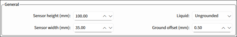
Sensor height (mm) – The height of the entire sensor stack-up. The range – 30.00-422.5, default – 100.00.
Sensor width (mm) – The width of the entire sensor stack-up. The range – 20.00-60.00, default – 35.00.
Liquid – Select whether the liquid is Ungrounded or Grounded. Default – Ungrounded.
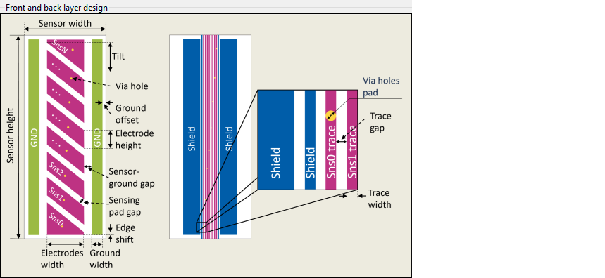
Ground offset (mm) – The spacing gap between the outer ground traces and the edge of the sensor area. The range – 0.5-15, default – 0.50.
Front layer
Select the relevant check box to use the parameter as an input parameter.
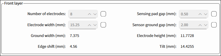
Number of electrodes – The total number of electrodes. The range – 3-32.
Electrode width (mm) – The horizontal width of each electrode. The range – 1-59.99.
Ground width (mm) – Read-only. The width of the ground traces.
Edge shift (mm) – Read-only. The edge shift area on the top and bottom electrodes. This value can be negative.
Sensing pad gap (mm) – The space between the electrodes. The range – 0.1-10.
Sensor-ground gap (mm) – The horizontal space between the electrodes and neighboring ground traces. The range – 0.1-10.
Electrode height (mm) – Read-only. The height of an electrode when measured at a single point on the horizontal axis.
Tilt (mm) – Read-only. The distance between the highest and lowest points of the tilted edge of an electrode.
Back layer

Trace width (mm) – The width of the trace, which connects some segment of the Liquid Level sensor with the connector. The range – 0.1-10, default – 0.30.
Trace gap (mm) – The distance between adjacent trace widths. The range – 0.1-10, default – 0.70.
Via holes pad (mm) – The diameter of through-hole pads for each sensor between the front and back layer. The range – 0.1-10, default – 0.70.
Generate DXF
Click this button to generate a *.dxf file of the calculated liquid level sensor to a specified file location.
Illustration of front and back layer design parameters
The illustrative image of the front and back layer design.