Input parameters
The
Input parameters
include
Overlay
,
Sensor
, and
PCB
parameters.
Note: The first output parameter will always be the same parameter, which is locked

in the Input parameters section. Lock the relevant parameter by double-clicking its unlocked icon

. Only one parameter can be locked at a time.
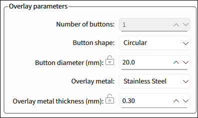
Overlay parameters
Rectangular | Circular |
|---|---|
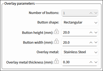 |  |
Number of buttons
– The number of buttons in the specified widget. Default – 1.
Button shape
– Rectangular, Circular. Default – Rectangular.
Button height (mm)
– Visible only for a rectangular button. For Cavity thickness/airgap, the dimensions are the same. The range is 8-28, default – 20.
Button width (mm)
– Visible only for a rectangular button. For Cavity height/width, the dimensions are the same. The range is 8-28, default – 20.
Button diameter (mm)
– Visible only for a circular button. The range is 8-28, default – 20.
Overlay metal
1
– Stainless Steel, Aluminum. Default – Stainless Steel.
Overlay metal thickness (mm)
– The thickness of the specified overlay. The range is 0.2-0.5, default – 0.30.
Stainless Steel – The range is 0.2-0.5, default – 0.30.
Aluminum – The range is 0.25-0.5, default – 0.30.
Sensor parameters
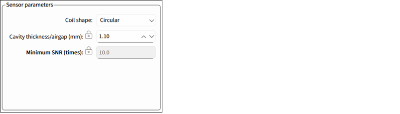
- Coil shape 2 – Circular, Rectangular, Hexagonal, Oval. Default – Circular.
Cavity thickness/airgap (mm) – The gap between the overlay and the sensor coil. The range is 0.3-7. Default – 1.10.
Minimum SNR (times) – The minimum SNR required for the sensor optimum performance. The range is 1-40.
PCB parameters
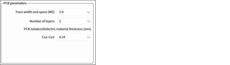
Trace width and space (Mil) – The minimum sensor PCB trace width for generating output parameters. Select from: 3.5, 4.0, 5.0, or 7.0. Default –5.
Number of layers – The number of Cu layers. Select from: 1, 2 or 4. Default – 2.
PCB isolator/dielectric material thickness (mm) – Enabled for more than 1 layer. The thickness of PCB Isolator or dielectric material used between Cu layers.
For 2 layers, Cu1-Cu2, select from: 0.24, 0.4, 1.0, 1.2. Default – 0.24.
For 4 layers, the spaces between the layers are fixed: 0.24 – 1.0 – 0.24.
Generate DXF
Click this button to generate a *.dxf file of the calculated liquid level sensor to a specified file location.
This button is disabled if the calculated value is beyond the allowed range and the first field of the
Output parameters
indicates that.
1
Titanium, Copper – not supported for this release.
2
Only Circular is supported for this release.