Multi-core debugging
This section explains how to set up multi-core debugging in the µVision IDE.
Supported debugger probes
KitProg3 on-board programmer
MiniProg4
ULINK2 in CMSIS-DAP mode
J-Link
Opening µVision multi-core projects
After you create a ModusToolbox™ multi-core application for use with µVision, do the following:
Navigate to the ModusToolbox™ project directory for one of the cores/projects and double-click project description file (either *.
cprj
or *.
cpdsc
depending on µVision version).
The first time you do this, a dialog may pop-up offering to install the missing CMSIS-Pack. Click
Yes
and the pack will be installed.
Repeat the same process for the other cores/projects. This will create and open corresponding µVision projects.
Building µVision multi-core projects
Once all projects are open, go ahead and build each one using
Project > Build target
.
Debugger configuration
Next, configure projects to launch multi-core debugging.
PSOC™ 6 and XMC7xxx applications
Configure CM0+ project
Go to
Project > Options for Target <target_name>
, switch to the
Debug
tab, select the applicable debug probe (CMSIS-DAP or J-Link) as shown:
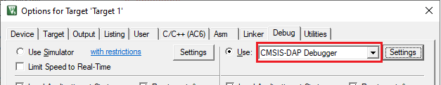
If using ULINK2, select the
CMSIS-DAP Debugger
option as the debug probe, because the ULINK2 driver does not support multi-core debugging
Click the
Settings
button to configure the target driver.
If you select the J-Link probe, a pop-up window might display reporting that the device is unknown to J-Link software.
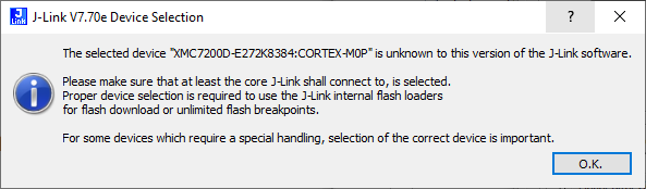
If so, click
OK
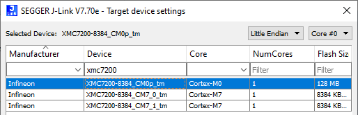
and select the device manually in the opened Target device settings dialog. For XMC7200 devices, there will be three aliases, each dedicated to a separate core.
Switch to the
Flash Download
tab, select the
Erase Sectors
radio button, and select the
Program
,
Verify
, and
Reset and Run
check boxes.
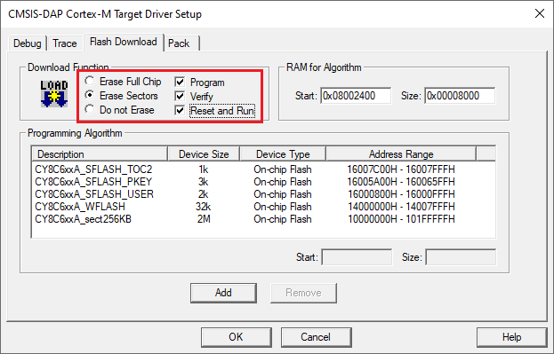
Click
OK
to close the Target Driver Setup dialog.
Next, configure the project so that it also programs other image(s) from the CM4/CM7 project(s). Do this using the *.
ini
file.
Create a new empty file named load_cmx.ini and save it inside the CM0+ project directory.
Add a LOAD command with a path to the CM4/CM7 images. For example:
LOAD "..\\proj_cm4\\proj_cm4_Objects\\proj_cm4.axf"Add as many LOAD commands for all the CM4/CM7 projects as you have.
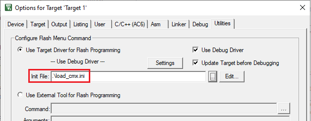
Go to
Project > Options for Target <target_name>
, select the
Utilities
tab, and specify the created
load_cmx.ini
file in the
Init File
edit field.
Switch to the
Debug
tab, and click the
Settings
button.
The configuration settings are different for CMSIS-DAP/ULINK2 and J-Link. Refer to the following sections for the applicable options:
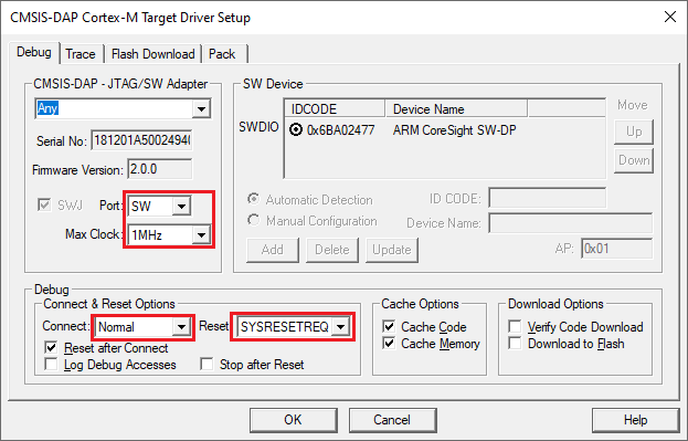
CMSIS-DAP/ULINK2 Target Driver Setup
Use the following options:
Port
: SW
Max Clock
: 1 MHz
Connect
: Normal
Reset
: SYSRESETREQ
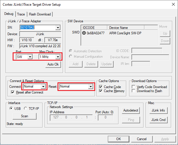
J-Link Target Driver Setup
Use the following options:
Port
: SW
Max clock
: 1 MHz
Connect
: Normal
Reset
: Normal
That completes configuring the CM0+ project. The next step is to configure CM4/CM7 project(s).
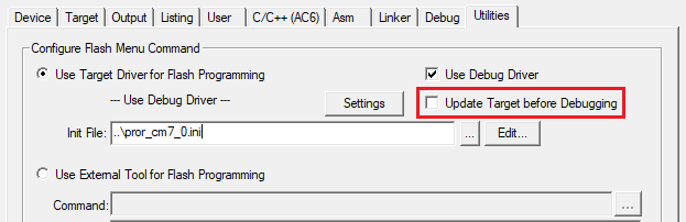
Configure CM4/CM7 project
Go to
e>
, switch to the
Utilities
tab, and deselect the
Update Target before the Debugging
check box.
Switch to the
Debug
tab, select the applicable debug probe (CMSIS-DAP or J-Link).
If using ULINK2, select the
CMSIS-DAP Debugger
option as the debug probe, the ULINK2 driver does not support multi-core debugging.
Click the
Settings
button to configure the target driver.
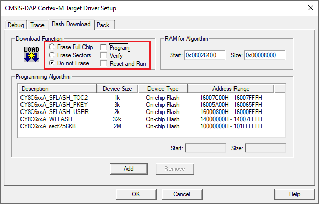
On the Target Driver Setup dialog, switch to the
Flash Download
tab, select the
Do not Erase
radio button, and deselect the
Program
,
Verify
, and
Reset and Run
check boxes.
Switch to the
Debug
tab.
The configuration settings are different for CMSIS-DAP/ULINK2 and J-Link. Refer to the following for the appropriate options:
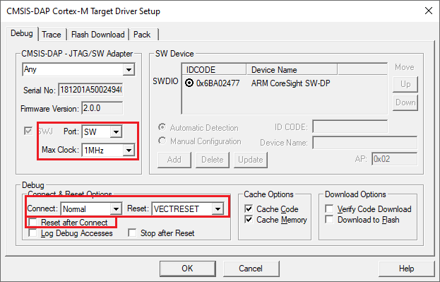
CMSIS-DAP/ULINK2 Target Driver Setup
– Use the following options:
Port
: SW
Max Clock
: 1 MHz
Connect
: Normal
Reset
: VECTRESET
Reset after Connect
check box: deselected
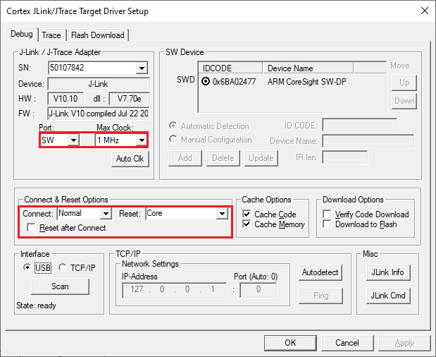
J-Link Target Driver Setup
– Use the following options:
Port
: SW
Max Clock
: 1 MHz
Connect
: Normal
Reset
: Core
Reset after Connect
check box: deselected
Click
OK
to close the Target Driver Setup dialog.
Save the project(s).
Launching multi-core debug session
To launch a multi-core debug session, all your µVision projects must be opened in separate IDE instances.
Open a µVision IDE session with the project for the CM0+ core and start debugging by pressing
Debug > Start/Stop Debug Session
. This will program all images, reset the target, and halt at the beginning of the CM0+ project
main()
.
Repeat the same process for the CM4/CM7 core(s). This will attach the running CM4/CM7 core that will be spinning in the boot code until the CM0+ project starts it.
Note:
Ensure both projects are built before launching a debug session.
For dual-core MCUs, the projects will be similar to these images:
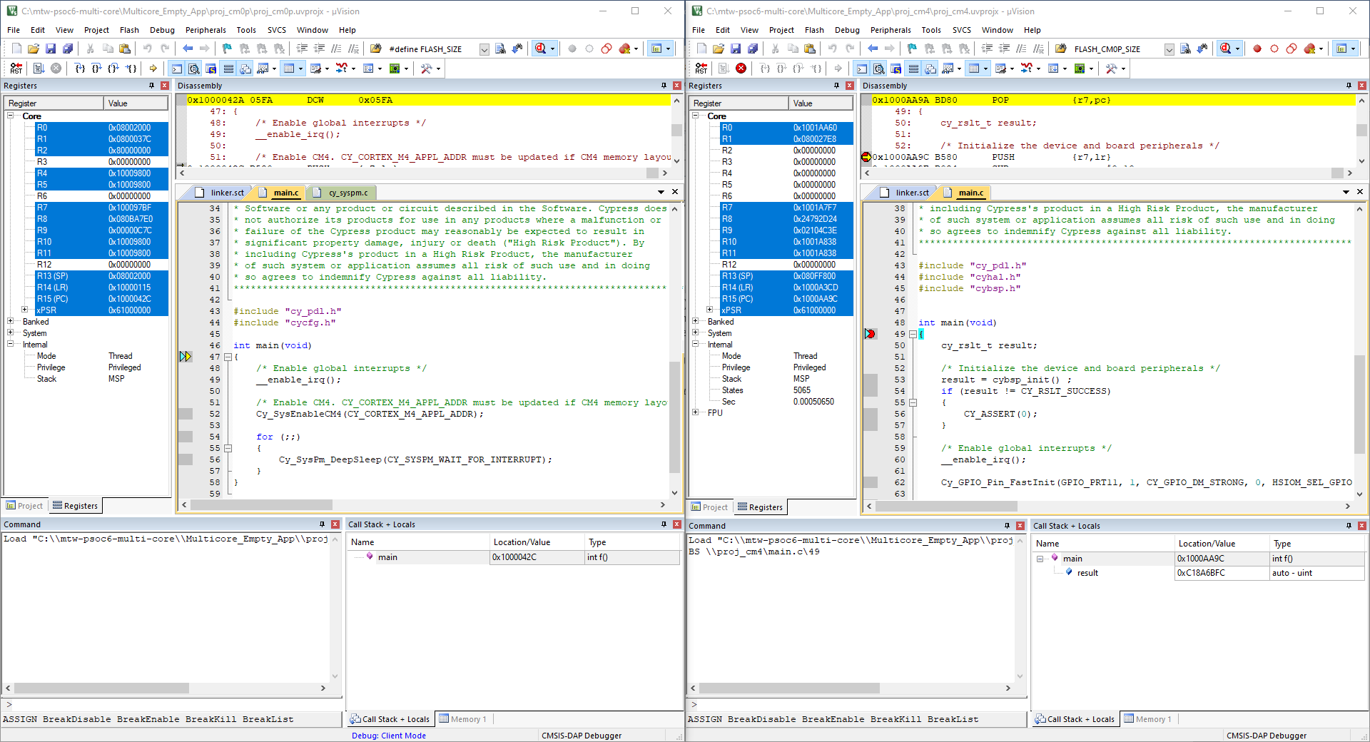
The left side of the screen shows a µVision IDE instance attached to the CM0+ core. The right side shows the CM4 core has not started yet. Once the
Cy_SysEnableCM4()
function on the CM0+ core has been executed, the CM4 will start executing its application. You can step through the code by switching back and forth between the two µVision IDE instances.
Launching PSOC™ 6 and XMC7xxx multi-core debug session
To launch a multi-core debug session, all your µVision projects must be opened in separate IDE instances.
Open a µVision IDE session with the project for the CM0+ core and start debugging by pressing
Debug > Start/Stop Debug Session
. This will program all images, reset the target, and halt at the beginning of the CM0+ project
main()
.
Repeat the same process for the CM4/CM7 core(s). This will attach the running CM4/CM7 core that will be spinning in the boot code until the CM0+ project starts it.
Note:
Ensure both projects are built before launching a debug session.
For dual-core MCUs, the projects will be similar to these images:
The left side of the screen shows a µVision IDE instance attached to the CM0+ core. The right side shows the CM4 core has not started yet. Once the
Cy_SysEnableCM4()
function on the CM0+ core has been executed, the CM4 will start executing its application. You can step through the code by switching back and forth between the two µVision IDE instances.