Programming/Debugging
Connect the development kit to the host PC.
XMC7000 and TRAVEO™ II specific steps
Because the XMC7000 and TRAVEO™ II devices have multiple cores – even if they are not used in a single-core application – you must perform special steps to modify the linker script for the IAR project.
See
XMC7000/TRAVEO™ II specific steps
for more details.
To use KitProg3/MiniProg4
As needed, run the fw-loader tool to make sure the board firmware is upgraded to KitProg3. See the
KitProg3 User Guide
for details. The tool is in the following directory by default:
<user_home>/ModusToolbox/tools_<version>/fw-loader/bin/
Select
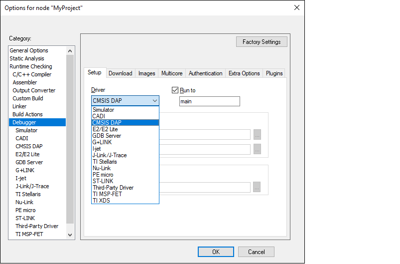
Project > Options > Debugger
and select CMSIS-DAP in the Driver list:
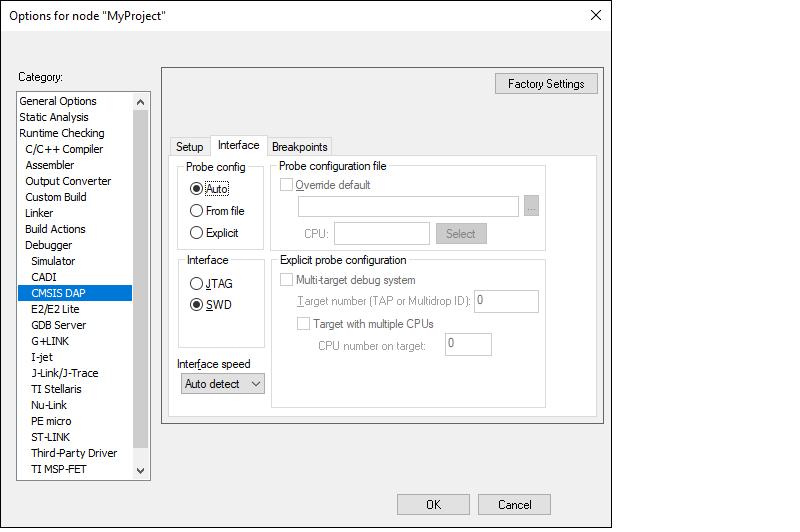
Select the
CMSIS-DAP
node, switch the interface from
JTAG
to
SWD
, and set the Interface speed to
2MHZ
.
Click
OK
.
Select
Project > Download and Debug
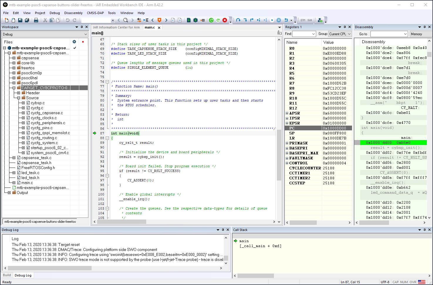
.
The IAR Embededed Workbench starts a debugging session and jumps to the main function.
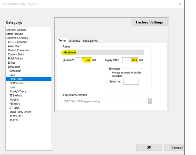
To use MiniProg4 with PSOC™ 6 single core and PSOC™ 6 256K
For a single-core PSOC™ 6 MCU, you must specify a special type of reset, as follows:
To use J-Link
You can use a J-Link debugger probe to debug the application.
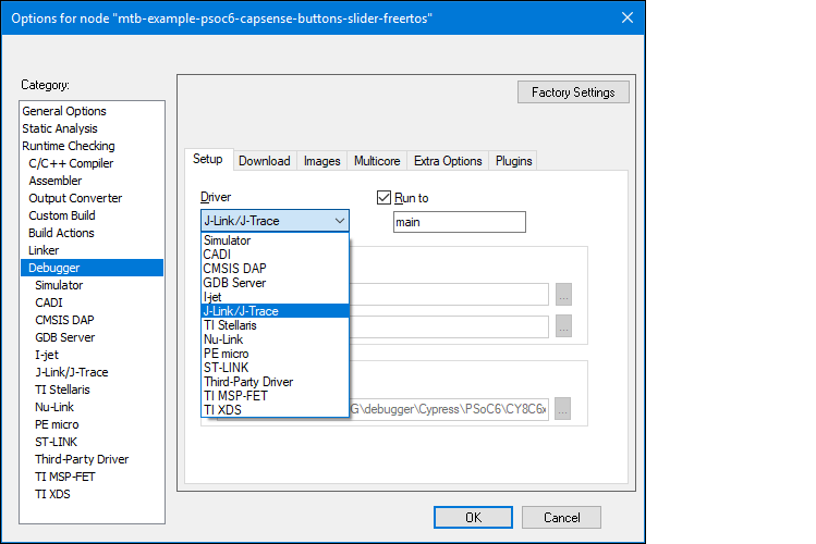
Open the Options dialog and select the
Debugger
item under
Category
.
Then select
J-Link/J-Trace
as the active driver:
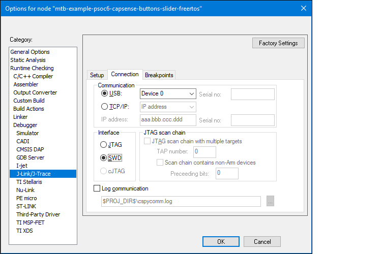
Select the
J-Link/J-Trace
item under
Category
, and under the
Connection
tab, switch the interface to
SWD
:
Note:
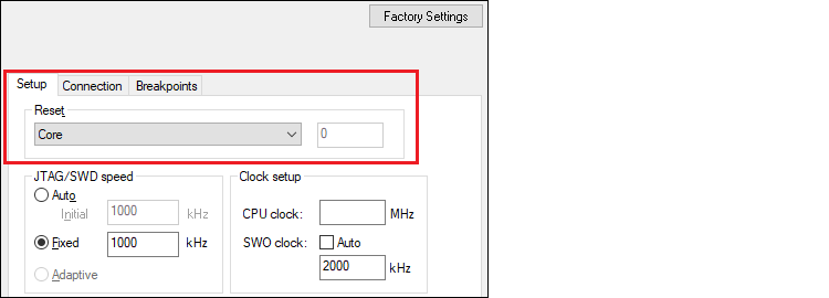
For PSOC™ 64 "Secure Boot" MCU, you must specify a special type of reset, as shown:
Connect a J-Link debug probe to the 10-pin adapter (this needs to be soldered on the prototyping kits), and start debugging.
Perform ETM/ITM trace
Program external memory
IAR Embedded Workbench has disabled external memory programming by default. The SMIF region in the *.board file must be enabled manually for PSOC™ 6 devices. To do that:
Open the Options dialog and select the
Debugger
item under
Category
.
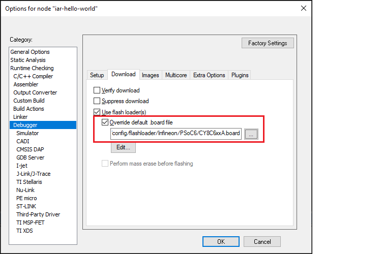
Click the
Download
tab and select the
Override default .board file
check box.
Identify the default .
board
file currently used for this project.
Copy the default .
board
file from the IAR Installation directory and paste it next to the IAR project file.
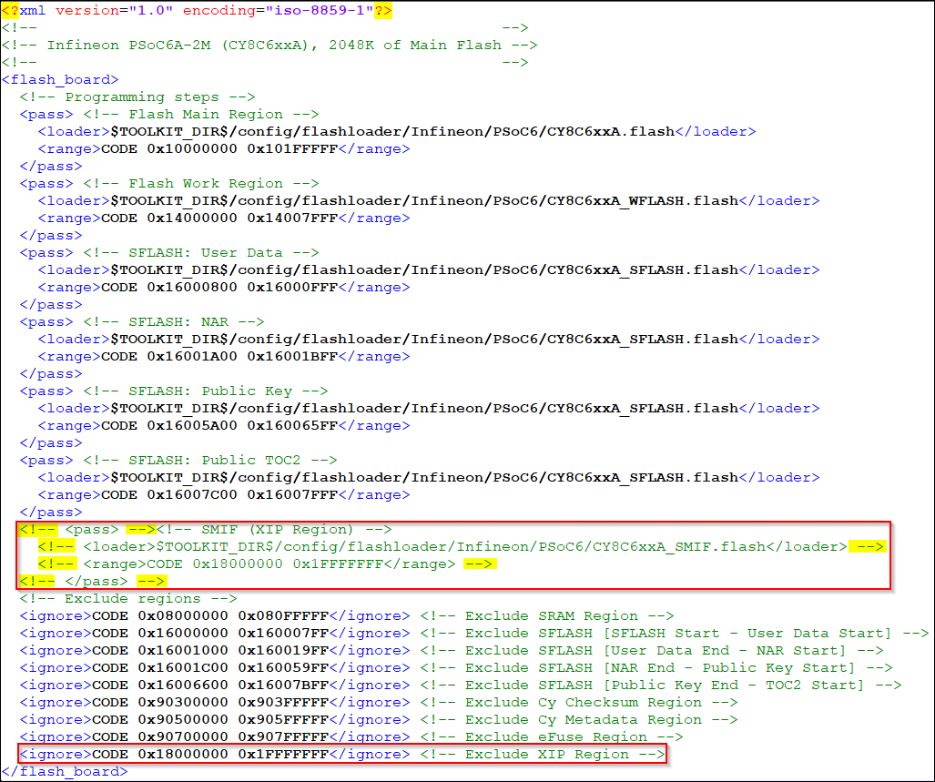
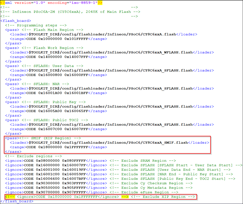
Use a text editor to remove comment tags for the SMIF region around the
<pass>
element, and then comment out the ignore element for the XIP region in the recently copied file.
Original file:
Edited file:
Save the file.
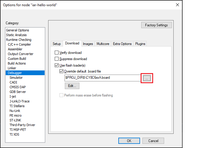
In IAR, click the
Browse […]
button, then navigate to and select the edited .
board
file.
Click
OK
when you are finished.
Erase PSOC™ 6 MCU with external memory enabled
To successfully erase external memory using flashloaders on PSOC™ 6 MCUs, the device's internal flash must contain valid QSPI configuration data. It may be part of a previously programmed application, such as the QSPI_XIP example. For more details, review section 7 of application note
AN228740
.
Select
Project > Download > Erase memory
.

Deselect the check boxes for all regions, except for 0x18000000-0x1fffffff.

Click
Erase
.
Select
Project > Download > Erase memory
again.
Select all other regions and deselect 0x18000000-0x1fffffff.

Click
Erase
.
Erase PSOC™ Control C3 memory
After successfully building a PSOC™ Control C3 application, you may encounter flash access restrictions based on the policy that was used to provision the target. The same physical flash memory can be erased/programmed over S-BUS either over Non-Secure addresses (0x22000000-0x2203FFFF) or over Secure addresses (0x32000000-0x3203FFFF).
During flash programming operations, the CPU core operates in the Secure world. In this state, the Non-secure addresses are always accessible, but Secure addresses may be unavailable if certain regions are configured for Non-secure access (for PSOC™ Control C3 it means Non-secure access only).
To erase the entire flash memory, it's important to only erase the non-secure range of addresses. Just deselect the secure address range:
