Installing and Using KitProg3
To use KitProg3, you need one or more of the following tools:
- ModusToolbox™ and ModusToolbox™ Programmer
- PSOC ™ Creator and PSOC ™ Programmer
- Any IDE that supports CMSIS-DAP Bulk protocol
- Bridge Control Panel (BCP) for USB-I 2 C and USB-SPI bridging
- A terminal emulator for USB-UART bridging
- A terminal that supports HID/Bulk USB communicational protocol
- A supported kit (see Supported Kits )
KitProg3 is communication firmware used by these tools. Bridge Control Panel is installed with PSOC™ Programmer. PSOC™ Programmer versions before 3.28.x do not support KitProg3.
Installing KitProg3
Install ModusToolbox™, ModusToolbox™ Programming tools, PSOC™ Creator, or PSOC™ Programmer before using any kit with KitProg3. Any required driver is installed by the tools that use KitProg3. There is no separate installer for KitProg3.
You can also get the latest version of KitProg3 delivered with the Firmware Loader available at the GitHub repository. The Firmware Loader does not install any drivers, but you can use it to upgrade (or downgrade) the KitProg firmware on a kit.
Support kits have either KitProg3 or KitProg2 already installed. See Upgrading to KitProg3 to learn how to tell what's installed, and how to upgrade.
When you plug in a kit, depending upon your circumstances and host operating system, you may see a message that drivers are being installed.
KitProg3 enumerates as a root USB Composite Device with subordinate CMSIS-DAP, Bridge, and USB-UART interfaces.
Using KitProg3
You do not use KitProg3 directly. You use a programming tool or IDE that automatically connects to and uses KitProg3. In most cases, KitProg3 is completely transparent.
Connecting
Plug in the kit. Use the USB cable that came with the kit and connect the host computer to the kit. KitProg3 is powered via the USB cable.
When you plug in the kit, an amber status LED indicates the current mode. On most kits, this is LED2. On MiniProg4, it is labeled Mode. The precise designation varies by kit.
If the LED is steady (out of box behavior), KitProg3 is using Bulk endpoints for faster communication. If the LED is ramping at 2 Hz, KitProg3 is in DAPLink mode. If the LED is ramping 1 Hz, KitProg3 is using HID endpoints, which means slower communication.
KitProg3 from the factory defaults to Bulk endpoints because they are faster. You can switch KitProg3 between Bulk and HID endpoints should you need to. See Mode Switching and fw-loader tool documentation.
Launch your programming tool or the Eclipse IDE for ModusToolbox™. The tool connects to KitProg3 automatically. The KitProg3 connection appears in the UI of the programming tool. Note that at this time, some programming tools do not recognize the kit if it is in DAPLink mode. Switch the kit to Bulk or HID, and the tool can see and work with the kit. See Mode Switching and fw-loader tool documentation.
Figure 1. Connected via ModusToolbox™ Programmer
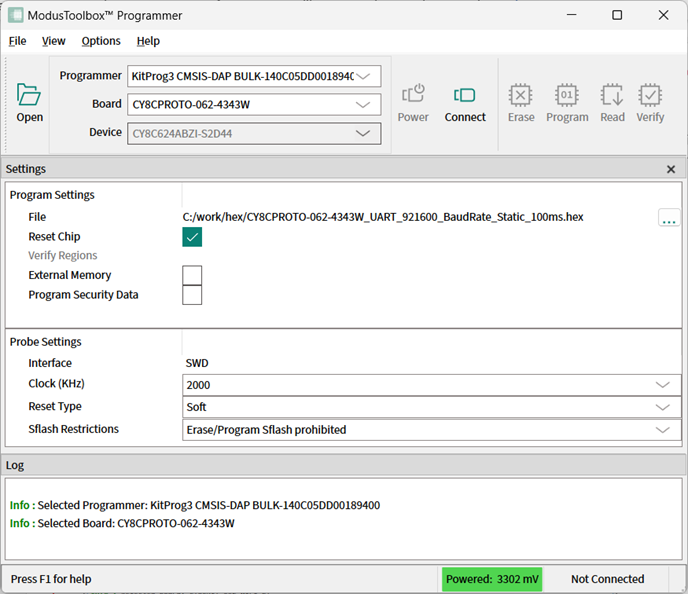
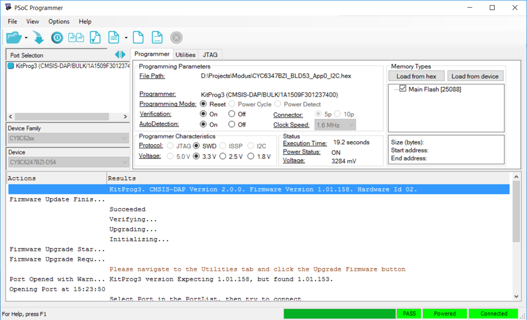
Figure 2. Connected via PSOC™ Programmer
Programming and Debugging
Use the program or debug commands in your tool. See your IDE's documentation for details.
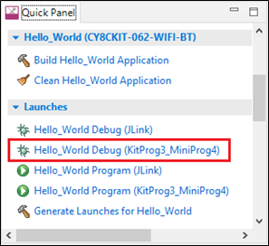
For example, for the Eclipse IDE, click the Debug (KitProg3_MiniProg4) link in the Quick Panel. To program the device without debugging, use the Program (KitProg3_MiniProg4) link.
Figure 3. Launching a Debug Session in Eclipse for ModusToolbox™
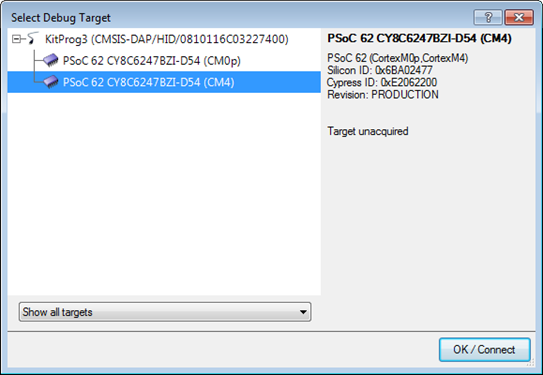
For PSOC™ Creator, use the Debug or Program commands in the Debug menu. Then select your target and click OK.
Figure 4. Selecting the Debug Target in PSOC™ Creator
Mode Switching
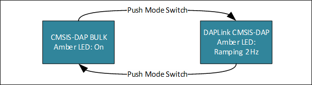
KitProg3 v1.20 and later supports CMSIS-DAP Bulk by default, and it may support Arm DAPLink mode. Each supported kit has a Mode Select switch (mode switch). Push the switch to cycle through the two modes: CMSIS-DAP Bulk and DAPLink. KitProg3 also supports CMSIS-DAP HID mode, but only through the Firmware Loader tool. See fw-loader tool documentation.
Figure 5. Mode switching in KitProg3
If a kit does not support DAPLink mode, mode switch will have no effect. See DAPLink Mode for supported kits.
The precise designation for the mode switch varies based on the kit. For example, on some CYPRESS™ Pioneer kits and the MiniProg4 debug probe, it is labeled Mode Select. Use your kit documentation if you can't find the switch. Starting from KitProg3 v1.11, the Custom App switch is deprecated and does not perform any action.
Switch to HID mode only if needed for your design or hardware. Otherwise, stay in Bulk mode for better performance during programming and debugging operations. Use DAPLink mode when required by your development workflow.
When in Bulk mode, the amber LED is ON and steady. In DAPLink mode the LED ramps at 2 Hz frequency. When in HID mode, the amber LED ramps up and down at 1 Hz frequency. In Bulk and HID modes, bridging (USB-I2C, USB-SPI, or USB-UART) is available while debugging with one exception: starting from KitProg3 v2.10, USB-I2C and USB-SPI bridging and debugging are mutually exclusive for Windows OS in CMSIS-DAP Bulk mode – see Troubleshooting for details. See KitProg3 LEDs for information on how KitProg uses the LEDs.
UARTx2 Mode
Some kits support a special operating mode that allows for two UART connections, rather than a single UART plus bridging (for example, USB-I2C or USB-SPI).
To enter UARTx2 if the kit is in DAPLink mode use the Firmware Loader tool. When the kit is in CMSIS-DAP Bulk or HID mode, press and hold the mode switch for at least two seconds. In UARTx2 mode, the amber LED blinks 1 second at 2 Hz then stays on for another second. To exit, press and hold the mode switch for at least two seconds. You return to CMSIS-DAP Bulk mode.
In and out of Bootloader Mode
If your KitProg3 image is corrupted, you can use bootloader mode to update the firmware. See Installing KitProg3 for information on where to get the KitProg3 image.
-
To get into Bootloader mode, press the Mode switch while plugging in the board.
-
To get out of Bootloader mode and return to normal operation, unplug the kit and reconnect without pressing the mode switch button.
KitProg3 LEDs
The KitProg3 user interface is limited to one or two mode switches and one or three status LEDs, depending upon the kit. The name and location of the mode switch(es) vary per kit. See the kit documentation to understand what switches and LEDs on the kit are used for KitProg3. See Mode Switching for information on how to use the mode switches.
The following table describes how KitProg3 uses LEDs to let you know what's going on. In CMSIS-DAP Bulk and CMSIS-DAP HID modes, green means success and red means there was a problem. In DAPLink mode the green LED flashes when the USB MSC interface is active, the red LED flashes when USB CDC interface is active.
| Mode Type | Programming Mode | Programming Status | Three LED Kit | Single LED Kit | ||
|---|---|---|---|---|---|---|
| Amber LED | Green LED | Red LED | Amber LED | |||
| User modes | CMSIS-DAP Bulk | Programming | ON | 8 Hz | OFF | 8 Hz |
| Success | ON | OFF | ON | |||
| Error | OFF | ON | Flashing 0.5 Hz Duty cycle = 5% | |||
| DAPLink | Ramping 2 Hz | Flashes when the USB MSC interface is active | Flashes when the USB CDC interface is active | Ramping 2 Hz | ||
| CMSIS-DAP Bulk with two UARTs | Programming | N/A | N/A | N/A | 8 Hz | |
| Success | 2 pulse of 2 Hz then 1 second on | |||||
| Error | Flashing 0.5 Hz Duty cycle = 5% | |||||
| CMSIS-DAP HID | Programming | Ramping 1 Hz | 8 Hz | OFF | 8 Hz | |
| Success | ON | OFF | Ramping 1 Hz | |||
| Error | OFF | ON | Flashing 0.5 Hz Duty cycle = 5% | |||
| Advanced modes | Bootloader | Not applicable | 1 Hz | N/A | N/A | 1 Hz |
Bridging Feature
For more information on bridging feature availability on supported devices refer to Supported Kits.
USB-UART Bridge Feature
This feature is available on all supported devices, and it can be accessed via any serial communicational terminal software to communicate with target device. Operating baud rates are described in Supported Kits, values of data bits, stop bit and parity are not configurable and always must be set to default values:
- Data bits – 8
- Parity – None
- Stop bits – 1
A second USB-UART interface is available only on some devices. To access this feature, see UARTx2 Mode.
If the device supports the UART Hardware Flow Control feature (refer to the "Supported Kits" section for details), you can configure use of this feature via Firmware Loader (fw-loader) commands. This configuration allows you to switch between "no hardware flow control" and "hardware flow control" as per your requirement.
Use this command to set UART flow control mode:
fw-loader --set-kp3-flow-conrol [port_number] [mode]
Use this command to read the current flow control mode set:
fw-loader --get-kp3-flow-control [port_number]
For supported values of [port_number] and [mode] parameters refer to Firmware Loader User Guide.
GPIO Bridge Feature
KitProg3 can be used for single wire communication with a target device via GPIO pins. There are two ways to use this feature; either through a USB HID/Bulk terminal or with the fw-loader command line tool (see Firmware Loader User Guide for more information). Two KitProg3 GPIO pins are connected to pins on the target device for this purpose: 3[5] (Port 3, Pin 5), 3[6] (Port 3, Pin 6).
You can send USB HID/Bulk requests to set drive mode, set state, read state, and detect state transitions of GPIO pins. Refer to the KitProg host protocol interface specification for descriptions of the commands.
You can also use fw-loader GPIO dedicated command line options to set mode and state of GPIO pin:
fw-loader --set-kp3-gpio-pin [pin_number] [pin_mode] [state]
Use this command to read the current state of a pin:
fw-loader --read-kp3-gpio-pin [pin_number]
For example, to set 3[5] (port 3, pin 5) GPIO pin to High state in ResUp operational mode, use
fw-loader --set-kp3-gpio-pin 35 ResUp 1
To read current state of 3[6] (port 3, pin 6) GPIO pin, use:
fw-loader --read-kp3-gpio-pin 36
USB-I2C/USB-SPI Bridge Feature
KitProg3 USB-SPI feature enables user to have communication between host and target device via I2C communication protocol, this feature is not available for all supported devices. See operating speeds for more details.
USB-SPI feature enables user to communicate between host and target device via SPI communicational interface, and is not available on all supported devices.
For more details on how use USB-I2C/USB-SPI Bridging via Bridge Control Panel (BCP), refer to Help documentation issued with the BCP.