AURIX™ DRIVECORE AUTOSAR [Infineon, Elektrobit, TASKING]
Getting Started Guide
About this document
Scope and purpose
DRIVECORE is a scalable software bundle portfolio that streamlines and accelerates software development. It simplifies processes, reduces migration efforts, and minimizes commercial complexities. DRIVECORE offers a seamless user experience throughout the R&D journey for Infineon's automotive microcontrollers: AURIX™, TRAVEO™, and PSOC™.
This document is created in a collaboration between Infineon and the partners of the specific bundle, to support you in the installation and set-up phase of the software, show code examples, and provide answers to common issues in this phase.
Introduction
Bundle overview
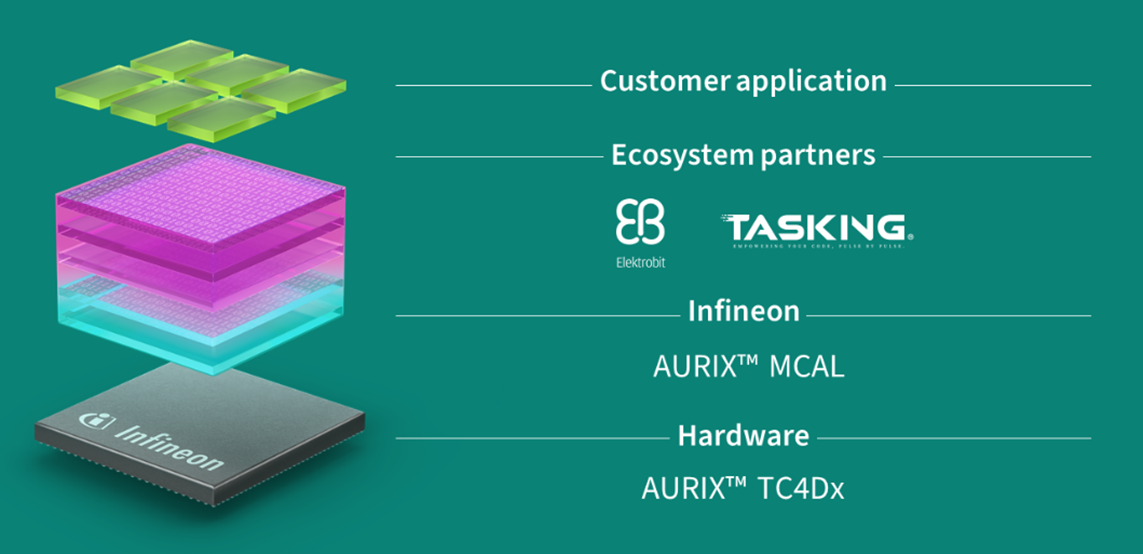
AURIX™ DRIVECORE AUTOSAR [Infineon, Elektrobit, TASKING] accelerates and simplifies the development of ECU software projects (AUTOSAR-based) and targets development of domain and zonal ECUs. With focus on performance and optimization, it combines high-performance hardware with pre-integrated software to deliver a fast, efficient, and scalable development experience.
This bundle integrates Infineon’s MCAL drivers, EB zoneo drivers for hardware acceleration, and EB tresos AutoCore, a mature Classic AUTOSAR Basic Software (BSW) stack. A key highlight of this bundle is the AUTOSAR gateway demo application, which shows optimized zonal ECU communication by leveraging hardware acceleration and software integration.
Combination of Infineon's AURIX™ microcontroller, Elektrobit’s software and TASKING’s certified SmartCode C/C++ Compiler Toolchain for TriCore™ and PPU provides a powerful solution which includes all components necessary for fast development and efficient ECU performance.
Figure 1.
Bundle overview
Software components
The purpose of this bundle is to show how the special Hardware accelerators for communication introduced in 32-bit TriCore™ AURIX™ TC4x microcontrollers can be configured within and work with Elektrobit’s basic Software and configuration tools for Classic AUTOSAR environment.
This bundle contains following software components:
Tool | Version | Description |
|---|---|---|
EB tresos 9 AutoCore OS | 6.1.275 | EB tresos 9 AutoCore OS is an AUTOSAR-compliant embedded multi-core real-time operating system. It is compatible with the OSEK/VDX operating system standard and supports all OSEK/VDX conformance classes. EB tresos AutoCore OS 6.1 is based on AUTOSAR 19-11 and Elektrobit-specific enhancements implemented compatible to the AUTOSAR standard. |
EB tresos 9 Autocore Base Package | 9.3.2 | AutoCore Generic Base Package provided by Elektrobit is based on the ICC3-compliant AUTOSAR layered architecture and contains hardware-independent basic software modules and the Runtime Environment (RTE). ACG version 9 (ACG9) is based on AUTOSAR R20-11. The features and interfaces of the basic software modules are implemented according to different AUTOSAR versions, with AUTOSAR R20-11 as baseline. |
EB tresos AutoCore Generic Ethernet Package | 9.3.2 | The EB tresos AutoCore Generic Ethernet Package product provides an Ethernet/IP stack for in-vehicular communication and diagnostic communication use cases including hardware-independent AUTOSAR basic software modules and the TCP/IP protocol family based on the Internet Protocol version 4 (IPv4) and version 6 (IPv6). |
EB zoneo ACM8 Eth | 1.0.0 | EB zoneo ACM8 Eth is a hardware-dependent basic software module that is implemented according to the AUTOSAR Specification of Ethernet Driver (Eth). |
EB zoneo GatewayCore | 1.0.0 | EB zoneo GatewayCore is a particular Elektrobit product that is developed to use, configure and integrate special communication hardware accelerators into the AUTOSAR Classic Platform. EB zoneo GatewayCore is a hardware-dependent module implemented as an AUTOSAR Classic complex device driver (CDD). It is designed to be integrated with the EB tresos product line. |
Tool | Version | Description |
EB tresos Studio for ACG 9 | 32.1.1 | EB tresos Studio is part of the EB tresos product line. The EB tresos product line offers efficient and scalable AUTOSAR-compliant and OSEK/VDX-compliant products for ECU development. EB tresos encompasses ECU basic software (BSW), single-/multi-core operating systems, functional safety and security solutions, and tools for configuration. |
TASKING SmartCode | v10.2.r1p1 | TASKING SmartCode is a TÜV NORD safety- and cybersecurity-certified C/C++ compiler toolchain for TriCore and PPU that supports ISO 26262 up to ASIL D, IEC 61508 up to SIL3, and ISO/SAE 21434:2021. It is qualified with Infineon MCAL packages and delivers best-in-class code execution performance. |
EB zoneo GatewayCore
EB zoneo GatewayCore is developed as a hardware-dependent CDD to support various hardware features and software interfaces on several layers of the AUTOSAR Classic Platform. EB zoneo GatewayCore consists of two main parts:
ComHWAcc
IEEE1722
Figure 2.
ComHwAcc
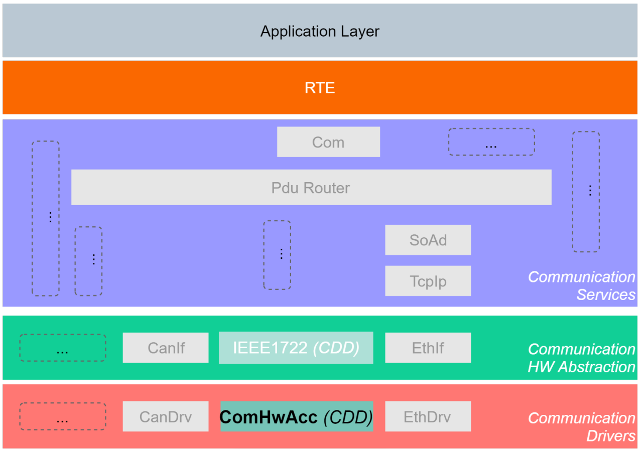
The main goal of the ComHwAcc module is to enable acceleration features for data processing available in the target hardware for the AUTOSAR Classic compatible COM stack of the EB tresos product line. The ComHwAcc can be considered as a communication driver (MCAL layer) designed to support TC4 hardware platform. For more information, please check the related documentation.
EB zoneo ACM8 Eth
ACM Eth is a hardware-dependent basic software module that is implemented according to the AUTOSAR Specification of Ethernet Driver (Eth). The module abstracts the hardware-related implementation details of specific Ethernet communication controllers and provides a uniform interface to the upper layer module via the Eth API. Thus, the AUTOSAR Ethernet Interface (EthIf) module as the user of the Eth module is independent of the underlying Ethernet communication controller hardware.
ACM Eth is compatible with the product EB tresos AutoCore Generic IP Stack. It requires EB tresos Studio for configuration and carrying out the code generation process. The product ACM Eth QoS Support can be requested optionally as add-on to ACM Eth.
Workflow
Introduction
This configuration work flow introduces the end-to-end work flow for generating ECU software using EB tresos Studio.
Provide Your Input Files. EB tresos Studio supports several standard file formats relevant for managing ECU configuration projects
EB tresos Studio supports AUTOSAR XML files containing:
System Description
LDF (Lin Description Format)
DBC
Import and Configure. GatewayCore Demo includes preconfigured files required by the ComHwAcc.
3
Generate Output Artifacts. After validation, EB tresos Studio produces all required build assets:
Code Generation for the configured AUTOSAR stack
Flash
See section
3.7
Files in Bundles
File name | Short description |
|---|---|
TASKING_SmartCode_10.2.1.zip | TASKING SmartCode Installer 2.2.1 |
TASKING_SmartCode_10.2.1p1.zip | TASKING SmartCode Patch Installer 2.2.2 |
winIDEA.7z | Preconfigured TASKING winIDEA workspace |
setup.bat | Helper script to install tresos, unzips module files automatically |
setup.exe | tresos installer |
Delivered | Contains software components and tools to be installed by setup |
Prerequisites
Before you start, make sure you have all the following files and applications with valid licenses available, as well as the target hardware.
Files:
EB-zoneo_GatewayCore_ComHwAcc_Userguide_Infineon_TRICORE_TC4DXX.pdf
Tresos.zip
setup.exe (EB tresos)
setup.bat (Installation script for EB tresos)
Delivered (Folder containing all necessary plugins)
Compiler: TASKING SmartCode v10.2r1p1
License keys:
EB tresos key
TASKING compiler key
Devices:
Evaluation board TriBoard TC4D9 Zone Gateway Board
Installation
Installation of EB tresos Studio
For introductory guidance on EB tresos Studio workflows, refer to the following resources:
Tutorials available under the Tutorials tab on the
Working with EB tresos Studio – Elektrobit
web page
It is recommended to use the setup.bat It will automatically recursively unzip the files ensuring that the installer finds all the modules. Setup.exe looks only the top level module files meaning the user has to extract zipped module files themselves
The Getting Started materials on the same web page
The Work flows view chapter in the EB tresos Studio User Guide, available at: $TRESOS_BASE/doc/2.-0_EB_tresos_Studio/2.1_Studio_documentation_users_guide.pdf
Install EB tresos Studio license
Install the workspace: the AutoCore OEM Extension Start-up Package Application workspace is delivered as an uip package and is installed with the EB tresos Studio installer
The license key for the tool is given in your Infineon Developer Center (IDC) portal
(Ensure to login to IDC using registered credentials)
Installation of TASKING SmartCode compiler
TASKING SmartCode v10.2r1p1 is used to build the GatewayCore example.
It's required to install the baseline software first (TASKING SmartCode v10.2r1) and to install the patch (TASKING SmartCode v10.2r1p1) as second step.
Installation of the baseline software TASKING SmartCode v10.2r1
The installation program is part of the Drive Core package and can be found in the zip file .\TASKING_SmartCode_v10.2r1.
Unzip the TASKING_SmartCode_v10.2r1and open the unzipped directory
Run the installation program (setup.exe). The TASKING Setup dialog box appears
Select the product and click on the Install button. If there is only one product, you can directly click on the Install button
Follow the instructions that appear on your screen. During the installation you need to enter the license key you've received as part of the Drive Core package
Note:
Make sure to specify an installation directory without any spaces, preferably one matching the default expected location for tresos toolchain
Note:
A node-locked server based license is used. The TASKING Remote License Server will bind the node-locked license to the computer that first uses the license.
For more details, please also check Getting Started with TASKING SmartCode
(https://www.tasking.com/support/smartcode/smartcode_getting_started_v10.2r1.pdf).
Installation of the patch
The installation program is part of the Drive Core package and can be found in the zip file .\TASKING_SmartCode_v10.2r1p1.
Unzip the FILENAME and open the unzipped directory
Run the installation program (setup.exe). The TASKING Setup dialog box appears
Select the product and click on the Install button. If there is only one product, you can directly click on the Install button
Follow the instructions that appear on your screen
HW setup
This chapter describes the required components for the hardware setup, how they are connected and the physical interfaces which are used.
Overview
Wiring diagram
shows the complete setup. The CAN GW extension boards are connected to the CAN0 and CAN1 connectors of the TC4D board. All used interfaces are shown in green, those are 6x CAN and 1x Ethernet.CDO:/content/authoring/xao1773405992291.image
Figure 3.
Block diagram of hardware setup
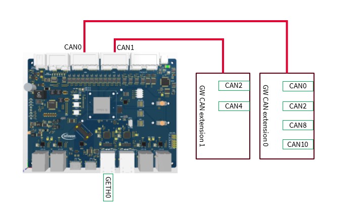
The following table shows how the physical interfaces are mapped to the sources and destinations, which are configured in tresos Studio.
CAN Connector | Tresos Configuration |
|---|---|
GW CAN extension 0 – CAN2 | CAN_Ctrl_0 |
GW CAN extension 0 – CAN4 | CAN_Ctrl_1 |
GW CAN extension 1 – CAN0 | CAN_Ctrl_2 |
GW CAN extension 1 – CAN2 | CAN_Ctrl_3 |
GW CAN extension 1 – CAN8 | CAN_Ctrl_4 |
GW CAN extension 1 – CAN10 | CAN_Ctrl_5 |
TC4D board – GETH0 | GETH0 |
Demo
Introduction
The demo project contains example configurations for different hardware accelerated routings and software based pdur routings.
Hardware accelerated:
CAN-to-CAN
CAN-to-MEM
ETH.IEEE1722-to-CAN
CAN-to-ETH.IEEE1722
Software pdur:
CAN-to-CAN
ETH-to-ETH
CAN-to-ETH
ETH-to-CAN
The naming schema of the routing entries follows the pattern:
Route_[CANID]_[SourceType]To[DestinationType][Unicast/Multicast]
.
CAN-to-ETH.IEEE1722 and ETH.IEEE1722-to-CAN require Eth/General/EthQoSSupport enabled (disabled by default in Tresos gui) which requires additional license.
The following subsections explain the individual Hardware accelerated routing entries in detail.
Name | Unicast/Multicast | Src / Dst Address | CAN Type | SrcCanCtrl | DstCanCtrl |
|---|---|---|---|---|---|
Route_1005_CanToCanU | Unicast | 1005 / 1005 | CAN2.0 | CAN_Ctrl_0 | CAN_Ctrl_1 |
Route_1008_CanToCanU | Unicast | 1008 / 1008 | CANFD | CAN_Ctrl_3 | CAN_Ctrl_4 |
Route_1012_CanToCanM | Multicast | 1012 / 1012 | CAN2.0 | CAN_Ctrl_0 | CAN_Ctrl_1 CAN_Ctrl_3 CAN_Ctrl_4 |
The CAN controllers are configured with following settings:
Name | HW Unit | Controller | CANFD active | Baud rate in kbps |
|---|---|---|---|---|
CAN_Ctrl_0 | 0 | 0 | false | 1000 |
CAN_Ctrl_1 | 0 | 1 | true | 1000 / 2000 |
CAN_Ctrl_2 | 0 | 3 | true | 1000 / 2000 |
CAN_Ctrl_3 | 1 | 0 | true | 1000 / 2000 |
CAN_Ctrl_4 | 1 | 1 | true | 1000 / 2000 |
Name | Unicast/Multicast | Src / Dst Address | CAN Type | SrcCanCtrl | DstCanCtrl |
|---|---|---|---|---|---|
Route_1001_CanToMemU | Unicast | 1003 / 1003 | CANFD | CAN_Ctrl_3 | CAN_Ctrl_4 |
Name | Unicast/Multicast | StreamId | CAN Address | CAN Type | SrcCtrl | DstCtrl |
|---|---|---|---|---|---|---|
Routing_1105_CanToEthU | Unicast | 103001 | 1005 | CAN2.0 | CAN_Ctrl_0 | GETH0 |
Name | Unicast/Multicast | StreamId | CAN Address | CAN Type | SrcCtrl | DstCtrl |
|---|---|---|---|---|---|---|
Routing_1108_EthToCanU | Unicast | 103001 | 1108 | CANFD | GETH0 | CAN_Ctrl_4 |
Routing_1111_EthToCanM | Multicast | 103004 | 1111 | CAN2.0 | GETH0 | CAN_Ctrl_1 CAN_Ctrl_3 CAN_Ctrl_4 |
The following subsections explain the individual Software pdur routing entries in detail.
Name | Unicast/Multicast | Src / Dst Address | CAN Type | SrcCanCtrl | DstCanCtrl |
|---|---|---|---|---|---|
Route_100 | Unicast | 100 / 100 | CAN2.0 | CAN_Ctrl_0 | CAN_Ctrl_1 |
Route_101 | Unicast | 101 / 101 | CAN2.0 → CANFD | CAN_Ctrl_0 | CAN_Ctrl_1 |
Route_102 | Unicast | 102 / 102 | CANFD → CAN2.0 | CAN_Ctrl_1 | CAN_Ctrl_0 |
Route_103 | Unicast | 103 / 103 | CANFD | CAN_Ctrl_2 | CAN_Ctrl_3 |
Route_104 | Multicast | 104 / 104 | CAN2.0 | CAN_Ctrl_0 | CAN_Ctrl_1 CAN_Ctrl_2 |
Route_105 | Multicast | 105 / 105 | CAN2.0 | CAN_Ctrl_0 | CAN_Ctrl_1 CAN_Ctrl_2 CAN_Ctrl_3 |
Route_106 | Multicast | 106 / 106 | CANFD | CAN_Ctrl_1 | CAN_Ctrl_2 CAN_Ctrl_3 |
Name | Unicast/Multicast | VLANID | CAN Address | CAN Type | SrcCtrl | SrcIP/ DstIP | SOAD ID |
|---|---|---|---|---|---|---|---|
Route_200 | Unicast | 4001 | 200 | CAN2.0 | CAN_Ctrl_0 | 192.168.1.11 192.168.1.22 | 200 |
Route_201 | Unicast | 4002 | 201 | CANFD | CAN_Ctrl_1 | 192.168.2.11 192.168.2.22 | 201 |
Route_202 | Multicast | 4001 / 4002 | 202 | CAN2.0 | CAN_Ctrl_0 | 192.168.1.11 192.168.1.22 / 192.168.2.11 192.168.2.22 | 202 |
Route_203 | Multicast | 4001/4002/4003 | 203 | CANFD | CAN_Ctrl_1 | 192.168.1.11 192.168.1.22 / 192.168.2.11 192.168.2.22 / 192.168.3.11 192.168.3.22 | 203 |
Name | Unicast/Multicast | VLANID | CAN Address | CAN Type | SrcIP/ DstIP | DstCtrl | SOAD ID |
|---|---|---|---|---|---|---|---|
Route_204 | Unicast | 4001 | 204 | CAN2.0 | 192.168.1.22 192.168.1.11 | CAN_Ctrl_0 | 204 |
Route_205 | Unicast | 4002 | 205 | CANFD | 192.168.2.22 192.168.2.11 | CAN_Ctrl_1 | 205 |
Route_206 | Multicast | 4003 | 206 | CAN2.0 | 192.168.3.22 192.168.3.11 | CAN_Ctrl_0 CAN_Ctrl_1 | 206 |
Route_207 | Multicast | 4004 | 207 | CANFD | 192.168.4.22 192.168.4.11 | CAN_Ctrl_1 CAN_Ctrl_2 CAN_Ctrl_3 | 207 |
Name | Unicast/Multicast | Source VLANID | Destination VLANID | Transmit SrcIP/ DstIP | Receive SrcIP/ DstIP | SOAD ID |
|---|---|---|---|---|---|---|
Route_400 | Unicast | 4001 | 4002 | 192.168.1.22 192.168.1.11 | 192.168.2.11 192.168.2.22 | 400 |
Route_401 | Multicast | 4001 | 4002/4003 | 192.168.1.22 192.168.1.11 | 192.168.2.11 192.168.2.22 / 192.168.3.11 192.168.3.22 | 401 |
Route_402 | Multicast | 4001 | 4002/4003/ 4004 | 192.168.1.22 192.168.1.11 | 192.168.2.11 192.168.2.22 / 192.168.3.11 192.168.3.22 / 192.168.4.11 192.168.4.22 | 402 |
Setup
This chapter describes how to import the EB tresos and EB zoneo GatewayCore example, prepare environment variables, and finally, how to build the project.
Setup example project
This section describes how to import the demo project.
Load EB tresos
Launch C:\EB\gwc_demo\tresos\tresos_gui.exe
Confirm creation of workspace directory
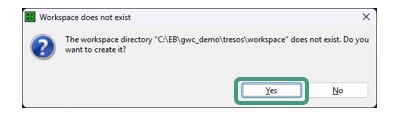
Select workspace directory to C:\EB\gwc_demo\tresos\workspace\
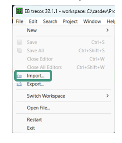
Once initialized, open the menu and select
File
→
Import…
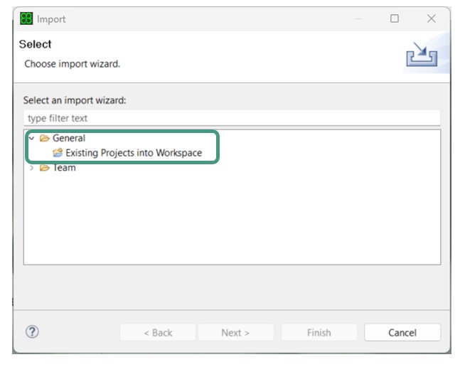
In the Import dialog, choose
General
→
Existing Project into Workspace
, then click on
Next
.
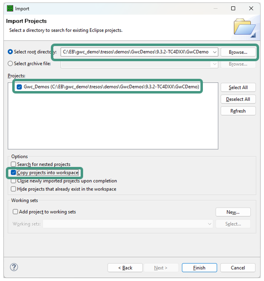
Click on
Browse…
and navigate to the desired project folder.
Make sure the GwCDemo Project is checked
Check Copy projects into workspace
Click on
Finish
to close the Import wizard and load the project
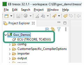
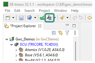
Generate
Expand
Gwc_Demos
Double-click
ECU (TRICORE, TC4DXX)
to load the project
Click
Generate
to generate the code for the project
Confirm code generation finished successfully dialog
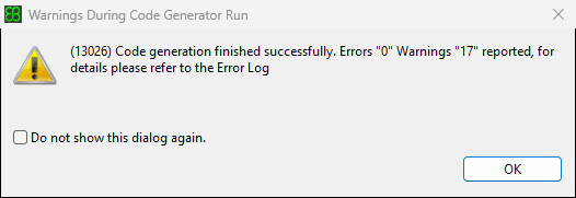
If the user wants to modify the pre-set routings, they need to save the changes and run the generate again. In case of using only the pre-set routings, EB tresos can be closed now
Configuration
The general setup for compiler paths and settings is configured by modifying the following file:
C:\EB\gwc_demo\tresos\demos\GwcDemos\9.3.2-TC4DXX\GwCDemo\util\launch_cfg.bat
This file is used to set the environment variables for the build system. If you use different paths than those listed specified in the launch_cfg.bat, they need to be adjusted accordingly:
TOOLPATH_COMPILER needs to point to \bin folder of the TASKING compiler toolchain
WORK_BASE needs to point to the working directory that contains EB tresos folder
Example:
SET TOOLPATH_COMPILER = C:/work/workspace/tools/toolchain/ctc
SET WORK_BASE = C:/EB/gwc_demo
Running the demo or build
To compile the application, following steps shall be taken:
Run \util\launch.bat
The configuration from the launch_cfg.bat is displayed
Run
make -j
to start the compilation
Note:
Successful generation of the code is required before compilation, either by tresos gui or
make generate
command. This also applies after calling make clean.
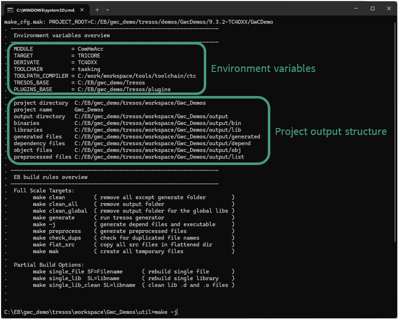
After successful compilation the binary can be found in the following folder:
C:\EB\gwc_demo\tresos\demos\GwcDemos\9.3.2-TC4DXX\GwCDemo\output\bin\
Finally, the actual flashing shall be performed. The TC4D Zone Gateway board supports different channels for programming and debugging.
On-board miniWiggler via the USB-C connector
10-pin DAP connector
10-pin DAPE connector
10 pin DAP_SCR connector
24-pin HSTCU connector
Please refer to the user manual of the TriBoard TC4D9 Zone Gateway Board ,
2.12. Program and Debug Interface
for further details about the interfaces.
Note:
The Drive Core package is debugger-agnostic and compatible with any debugger supporting the TC4 architecture. One option is the TASKING winIDEA.
TASKING winIDEA (optional)
The DRIVECORE package includes a preconfigured TASKING winIDEA workspace to simplify the initial setup and provide a smooth start into flashing and debugging the GatewayCore example.
Installation of winIDEA
Download the latest version of TASKING winIDEA
Follow the official Installation Guide (
https://www.isystem.com/downloads/winIDEA/help/winidea-installation-guide.html
)
Note:
winIDEA requires a license which is not contained in the Drive Core package. If you want to use or evaluate winIDEA, please contact TASKING (https://www.tasking.com/contact/).
Debugging with winIDEA
The preconfigured TASKING winIDEA workspace is located under .\<installDir>\workspace\Gwc_Demos\winIDEA\.
Please start winIDEA and load this winIDEA workspace.
The provided winIDEA workspace is configured for Symmetric Multi-Processing (SMP), enabling efficient debugging in a multi-core environment.
For more details about winIDEA, refer to (https://www.isystem.com/downloads/winIDEA/help/index.html) or contact TASKING.
Please refer to
for more information about the TASKING toolchain for flashing and debugging.
Development resources
ComHwAcc Configuration
GwCDemo contains ComHwAcc Userguide under the following folder after Tresos studio and modules are installed:
.\Tresos\demos\GwcDemos\9.3.2-TC4DXX\GwCDemo\doc\
PDUR routing configuration
Following section gives a short guide how to add/adjust pdur configurations in Tresos, it relies on already existing configurations set in the Demo project. If the user is not familiar with the underlying mechanisms, it is recommended to use the existing configurations.
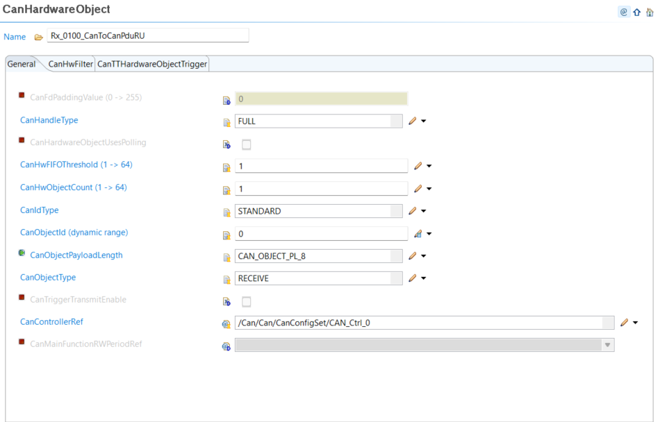
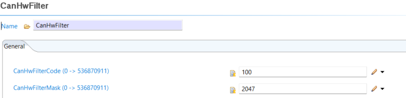
CAN receive
Configure Can/CanHardwareObject with a filter using the CAN ID as CanHwFilterCode
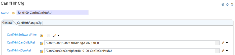
Configure CanIfI/CanIfInitHohCfg/CanIfHrhCfg/CanIfInitHohCfg
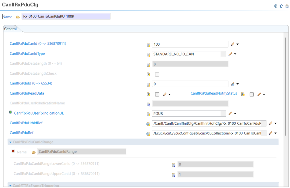
Configure CanIf/CanIfRxPduCfg
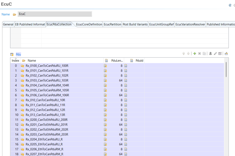
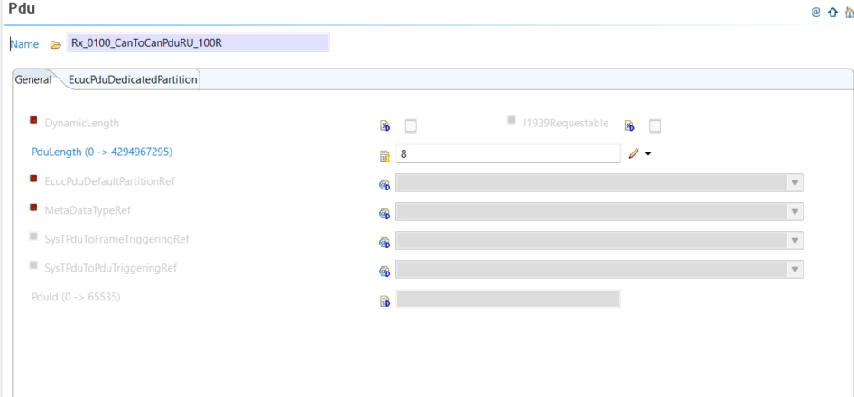
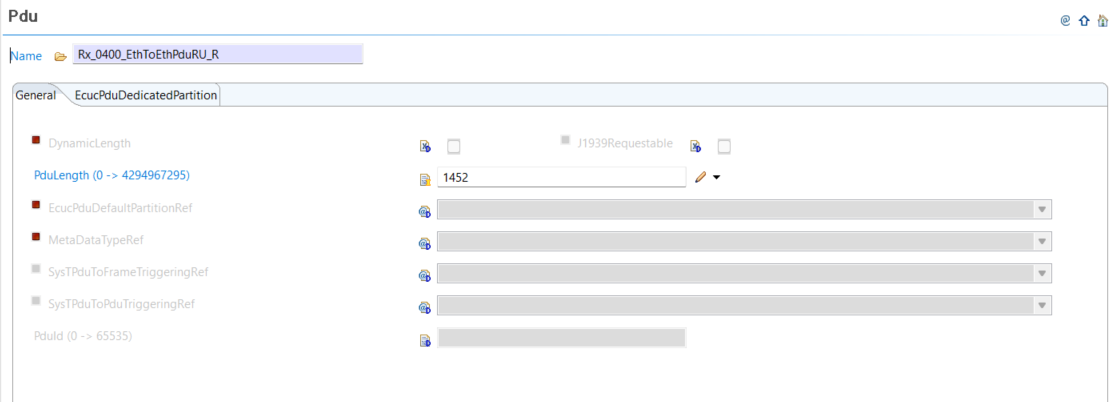
Configure EcuC/EcucPduCollection Pdu for receive
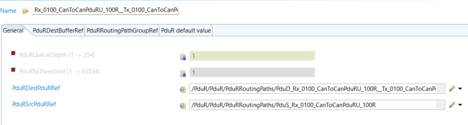
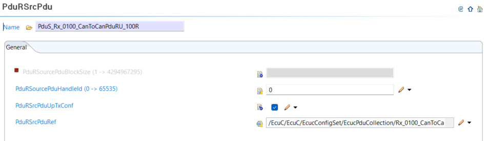
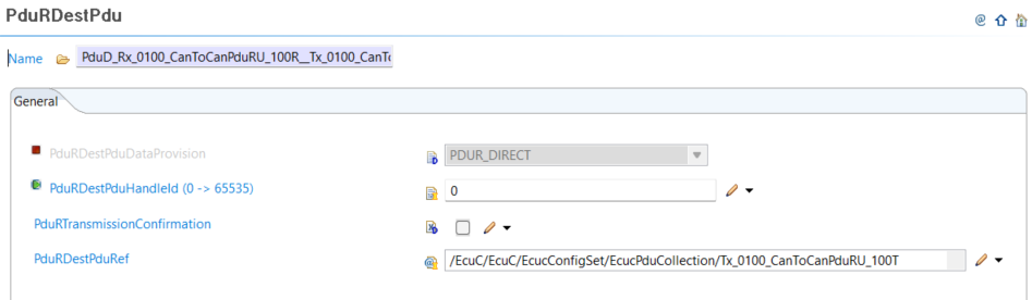
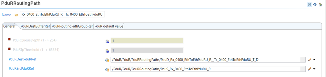
Configure Pdur/PdurRRoutingPath with PdurSrcPdu and PdurDestPdu where the latter matches ETH or CAN transmit routing
CAN transmit
Similar to the receive side
Configure Can/CanHardWareObject (of use existing one) without CanHwFilter
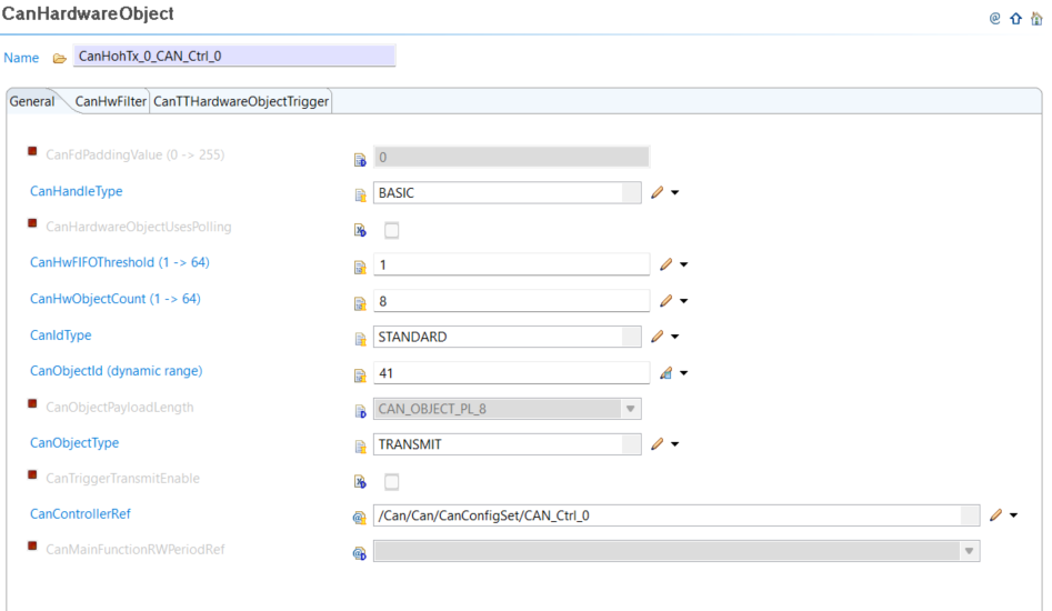
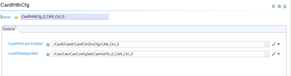
Configure CanIf/CanIfInitHohCfg/CanIfHthCfg (or use existing one)
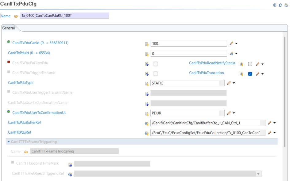
Configure CanIf/CanIfTxPduCfg
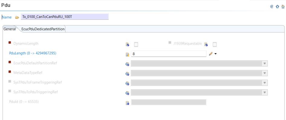
Configure EcuC/EcuCPduCollection Pdu for transmit
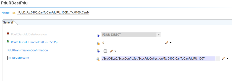
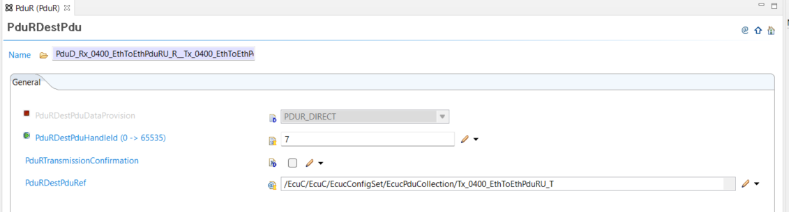
Configure PduR/PdurRDestPdu and attach it to the the PdurRoutingPath. See Can receive section PDUR part
ETH transmit
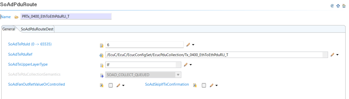
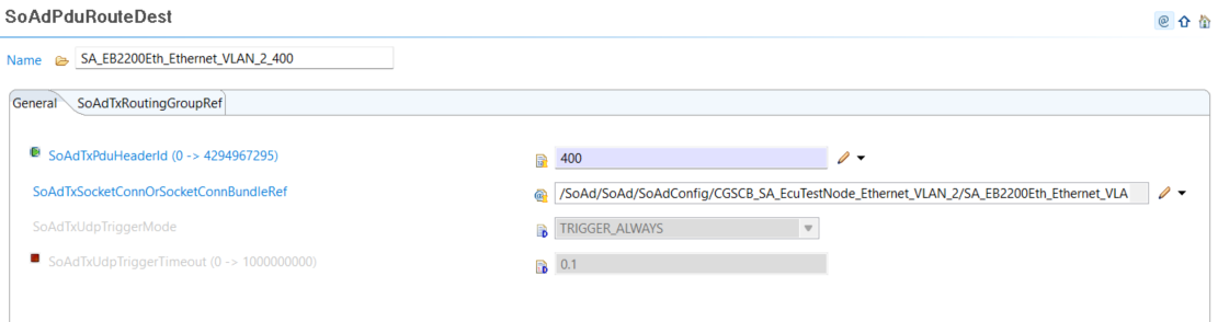
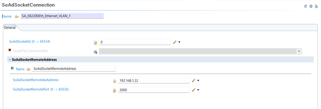
Configure SoAd/SoAdPduRoute with SoAdPduRouteDest
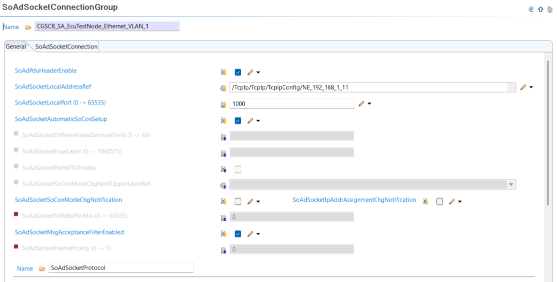
If not using existing one, add and configure SoAd/SoAdSocketConnectionGroup with SoAdSocketConnection
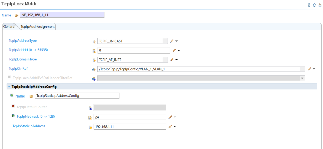
Configure TcpIp/TcpIpLocalAddr configs
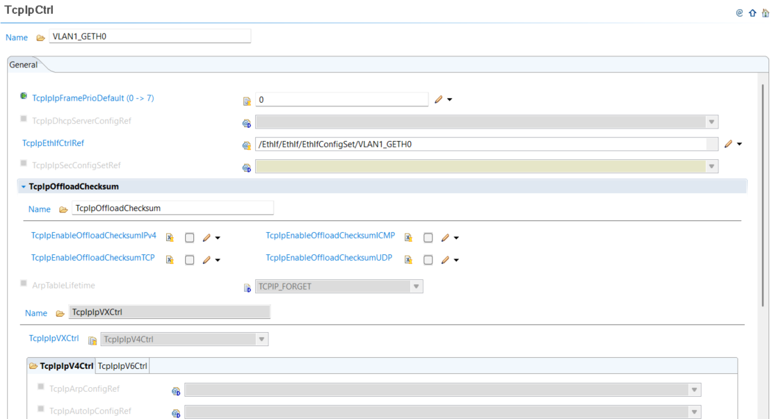
Configure TcpIp/TcpIpCtrl, this will be linked to the EthIfCtrl
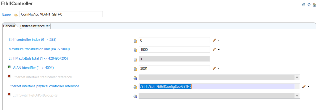
Configure EthIf/EthIfController
Configure ComM/ComMConfigSet/NetworkChannel and add a user to the channel (User Per channel, pointing to Configure ComM/ComMConfigSet/Users)
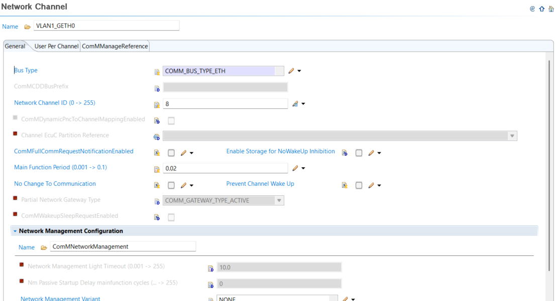
If user opts to create a new channel it is required to run the multitask wizard to make the newly created COMM channel visible for Event/Task mapping and then to switch to the RTE editor EVENT mapping and map the newly created Event to mode handling task
Configure PduR/PduRDestPdu
ETH receive
Configure SoAd/SoAdSocketRoute alongside its destination
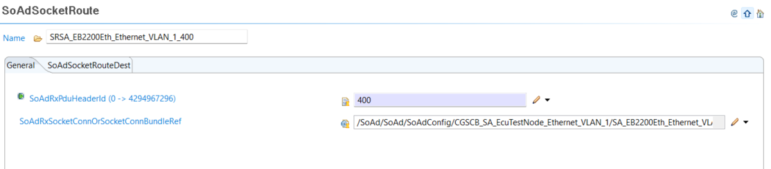
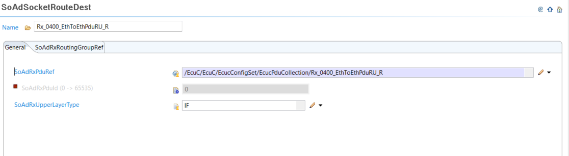
Configure EcuC/EcuCPduCollection receive PDU
Configure PduR/PduRRoutingPath and link the destination to CAN transmit or ETH transmit configuration
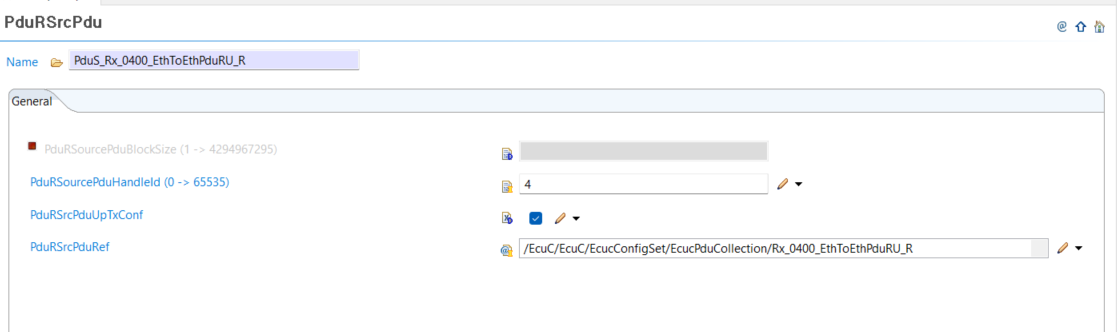
Configure PduR/PduRSrcPdu
Support
Contact support
MyCases
In the event of any problems, issues, or questions, please do not hesitate to reach out to your designated Infineon contact or Field Application Engineer (FAE) for assistance. Alternatively, you can also submit a request through our ticketing system
. For more information on how to use the myCases portal, please refer to this
document
.
Partners
By contacting support, you agree that your request and contact details are shared between
Elektrobit Automotive GmbH
,
IAR Systems
, and Infineon.
Troubleshooting
Compiler not found
<INSTALL_DIR>.\tresos\demos\GwcDemos\9.3.2-TC4DXX\GwCDemo\util>make -j
<INSTALL_DIR>./tresos/plugins/Compiler_TS_TxDxM1I0R0/make/TRICORE/tasking/Compiler_defs.mak:56: *** FILE DOES NOT EXIST CPP "C:/Program Files/TASKING/SmartCode v10.2r1/ctc"/bin/cptc.exe . Stop.
Do not enclose TOOLPATH_COMPILER in quotation marks, as quotation marks interfere with automatic path‑suffix appending.
Compiler install directory should not have white spaces in it (e.g. C:\Program Files\Tasking). This can break the make file path resolution.
CAN to ETH.IEEE1722 or ETH.IEEE1722 to CAN frame forwarding issues
Can to Eth in hardware and vice-versa requires EthQoSSupport enabled. Make sure config changes are saved (ctrl+s) after enabling the setting and before generating the code and running make -j.
No rule to make target
If running make -j command and getting error “No rule to make target <INSTALL_PATH>//Tresos/demos/GwcDemos/9.3.2-TC4DXX/GwCDemo/output/<output or generated file>, needed by …” ensure that make generate was successfully executed either via tresos gui or launch.bat make generate call. Deleting output directory and re-running make generate is recommended if the problem persists.
Missing modules
If modules are missing/unavailable during the importing of the Gwc_Demos (Upgrade/Remove Module Configuration), user should confirm that modules are installed within the plugins folder.
.\tresos\plugins<PluginName>_TS_VERSION. For example .\tresos\plugins\Compiler_TS_TxDxM1I0R0
This can occur if user tries to install Tresos studio with setup.exe without unzipping software component zip packages or without installing modules afterwards (rerunning installer after unzipping archives)
Recommended to use the setup.bat that extracts all the modules.
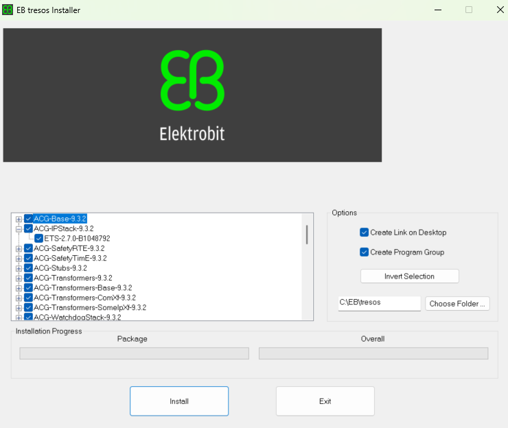
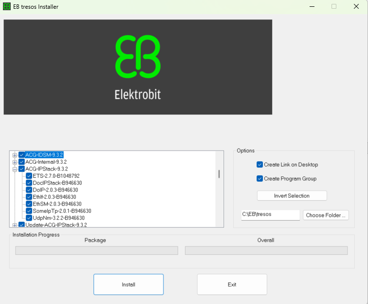
setup.bat with modules found