AURIX™ DRIVECORE AUTOSAR [Infineon, iSOFT, TASKING]
Getting Started Guide
About this document
Scope and purpose
DRIVECORE is a scalable software bundle portfolio that streamlines and accelerates software development. It simplifies processes, reduces migration efforts, and minimizes commercial complexities. Drive Core offers a seamless user experience throughout the R&D journey for Infineon’s automotive microcontrollers: AURIX™, TRAVEO™, and PSOC™.
This document is created in a collaboration between Infineon and the partners of the specific bundle, to support you in the installation and set-up phase of the software, show code examples, and provide answers to common issues in this phase.
Intended audience
Engineers who integrate with the iSOFT toolchain and the TC4D7 development board.
Introduction
Bundle overview
Drive Core is a scalable software bundle portfolio for AURIX™, TRAVEO™, and PSOC™ that facilitates a rapid start into Automotive software development.
Developed through close collaboration between Infineon and CP AUTOSAR toolchain providers, AURIX™ Drive Core AUTOSAR [Infineon, iSOFT, TASKING] is designed to reduce development complexity, costs, and time-to-market, while enhancing overall development productivity.
This comprehensive bundle empowers developers to quickly and efficiently tackle sophisticated design challenges.
The bundle includes:
Infineon’s MCAL drivers for reliable hardware abstraction
iSOFT’s ORIENTAIS Toolchain, featuring
SWC Builder for streamlined Application Software (ASW) design
BSW Configurator for efficient Basic Software (BSW) customization
A pre-integrated real-time operating system for out-of-the-box performance
A demo project to quickly demonstrate the communication flow from ASW to BSW
TASKING’s latest certified TC4x Tool Chain SmartCode
Software components
Tool | Version | Description |
|---|---|---|
SmartCode Eclipse IDE | v10.3r1 | Used for compiling TC4D7 projects |
Universal Debug Engine | 2024.02 | Used for downloading and debugging |
ORIENTAIS_Configurator | v2.2 | Used for configuring BSW |
ORIENTAIS_SWC_Builder | v2.2 | Used for configuring SWC |
EB tresos | V29.7.5 | Used for configuring MCAL |
AURIX_TC4x_MC-ISAR | v2.10.0 | The installation package of MCAL includes the system boot file, the source code of MCAL and the documentation of MCAL |
BUSMASTER | v3.2.2.25 | Used for sending and receiving TC4D7 messages |
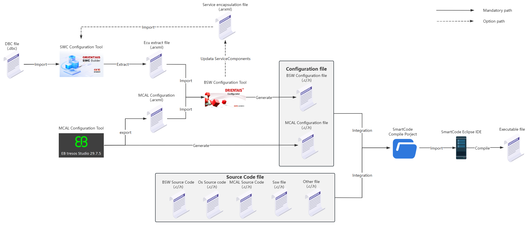
Workflow
Integrated workflow of the Demo project:
Create the SWC project in the SWC Configuration Tool, import the BSW service encapsulation file generated in step 3 (optional), create the application SWC Type, SWC instance, Port connection, and the mapping from the SWC instance to the ECU. Import the DBC file, perform SignalMapping, as well as ECU partitioning and partition mapping. Perform ECU extraction to obtain the ECU extract file
Create the MCAL project in the MCAL Configuration Tool, complete the configuration of the MCAL module, generate the SchM file, MemMap file and MCAL configuration file (.c/.h format) of the MCAL module, and export the MCAL configuration (.arxml format)
Create the BSW project in the BSW Configuration Tool. Import the ECU extract file generated in step 1 and the MCAL configuration generated in step 2 (.arxml format) into the BSW project to complete the configuration of the BSW module and generate the service encapsulation file of the module (optional). Update the bswmd file of the BSW module (Update Bswmd), synchronize Rte/Os (Synchronized Rte/iRte-Os), and generate configuration files
Create a compilation project in the SmartCode Eclipse IDE, integrate the MCAL configuration file generated in step 2, the BSW module configuration file generated in step 3, and various Source Code files into the compilation project for compilation
Figure 1. Workflow
The compilation project can be organized according to the following file structure:
Figure 2. Project directory structure diagram
The following table is a description of the project directory structure:
Level 1 Path | Level 2 Path | Level 3 Path | Level 4 Path | Description |
|---|---|---|---|---|
01_OrientaisProject | Stores the BSW module configuration project | |||
02_TaskingProject | src | App | Stores Application code for users to utilize | |
BSW | BswCode | Stores the source code of the BSW modules | ||
BswConfig | Stores the configuration of the BSW modules | |||
Intergration | Stores additional source code for integration | |||
LinkFile | Stores linker files | |||
MCAL | MCALCode | Stores the source code of the MCAL modules | ||
MCALConfig | Stores the configuration of the MCAL modules | |||
SSw | Cfg | Stores the configuration for the startup code | ||
Ssc_VM_Disable | Stores the non-virtualized startup code | |||
03_SwcProject | Stores the configuration project for the SWC Application | |||
04_McalProject | Stores the MCAL configuration project | |||
Files in bundle
File name | Short description |
|---|---|
ORIENTAIS_Configurator_User_Installation_Manual.pdf | The installation guidance for the BSW configuration tool |
ORIENTAIS_SWC_Builder_User_Installation_Manual.pdf | The installation guidance for the SWC configuration tool |
ORIENTAIS_SWC_Builder_2.0_Feature_Manual.pdf | Guidance on the Use of SWC configuration tools |
ORIENTAIS_Configurator_V2.2_User_Manual.pdf | Guidance on the Use of BSW configuration tools |
Installation
ORIENTAIS AUTOSAR toolchain setup
License keys
After the installation is complete, when you open the tool for the first time, a pop-up window will appear. Enter the license in the pop-up window.
Figure 3. Login Window
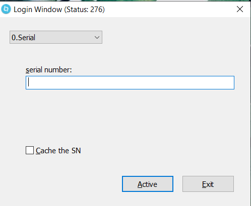
This license code supports the use of both ORIENTAIS Configurator and ORIENTAIS SWC Builder tools, but is only for one person to use online at a time, with a validity period of 90 days. If there are any verification issues, please delete C:\ProgramData\BitAnswer and try to re-authorize.
Installation
ORIENTAIS_Configurator installation excute file location:
..\iSOFT\Tool_Package\ ORIENTAIS Configurator V2.2_installer\ORIENTAIS_Configurator_V2.2.exe
ORIENTAIS_SWC_Builder installation excute file location:
..\iSOFT\Tool_Package\ ORIENTAIS SWC Builder V2.2_installer\ ORIENTAIS_SWC_Builder _V2.2.exe
For the installation of the iSOFT toolchain, please refer to the following documentation:
BSW Configuration Tool: ORIENTAIS_Configurator_User_Installation_Manual.pdf
SWC Configuration Tool: ORIENTAIS_SWC_Builder_User_Installation_Manual.pdf
Location:
..\iSOFT\Tool_User_Manual\ ORIENTAIS_Configurator_User_Installation_Manual.pdf
..\iSOFT\Tool_User_Manual\ ORIENTAIS_SWC_Builder_User_Installation_Manual.pdf
Install the remaining software on your own or consult their respective installation guides.
During installation, please note:
When installing the Tasking client, enter the correct license and connect to the remote or locally deployed Tasking License Manager Server (TLM Server)
When installing EB tresos 29.7.5, a valid license is required
When installing AURIX_TC4x_MC-ISAR_2.10.0, a valid license is required
Setup and configuration
For the setup of the iSOFT toolchain, please refer to the following documentation:
ORIENTAIS_SWC_Builder_2.0_User_Manual_Software_Design.pdf
ORIENTAIS_SWC_Builder_2.0_User_Manual_Overview.pdf
ORIENTAIS_SWC_Builder_2.0_User_Manual_Feature.pdf
ORIENTAIS_Configurator_V2.2_User_Manual.pdf
Location:
..\iSOFT\Tool_User_Manual\ORIENTAIS_SWC_Builder_2.0_User_Manual_Software_Design.pdf
..\iSOFT\Tool_User_Manual\ORIENTAIS_SWC_Builder_2.0_User_Manual_Overview.pdf
..\iSOFT\Tool_User_Manual\ ORIENTAIS_SWC_Builder_2.0_User_Manual_Feature.pdf
..\iSOFT\Tool_User_Manual\ORIENTAIS_Configurator_V2.2_User_Manual.pdf
HW setup
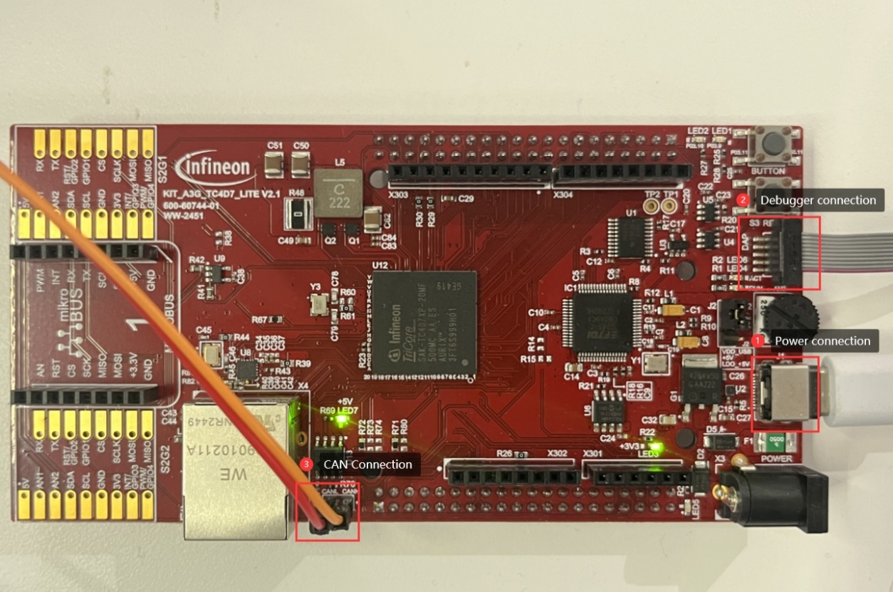
Board description
Overview
Please use the hardware development board with version KIT_A3G_TC4D7_Lite v2.1 and chip partnumber SAK-TC4D7XP-20MF500MC AB.
Setup
Power Connection
The TC4D7 board requires an external DC supply, which can be fed either through the barrel jack X3 (+7V ~ +14V) or the USB-C connector (+5V). LEDs LED3 and LED4 indicate the presence of the +3.3V and +5.0V rails. For this project the board is powered via USB-C
Debugger Connection
The TC4D7 board must be connected to an external debugger via Infineon’s 10-pin Device Access Port (DAP). This project uses the Universal Access Device 2pro for flashing and debugging
CAN Connection
The TC4D7 board needs to be connected to an external CAN bus debugger through Infineon’s high-speed CAN transceiver TLE9371VSJ. In this project, BUSMUST (external CAN debugger hardware) and BUSMASTER (the corresponding software for the external CAN debugger) are used for debugging CAN-bus-related protocol stacks
CAN requires the configuration of three pins: CAN_TX (P01.3, ALT5), CAN_RX (P01.4, GPIO), and CAN_STB (P03.5, GPIO, this pin must be driven low)
Image
Figure 4. Board image
Demo
Introduction
This Demo is integrated based on the AURIX™ TC4D7 development board, including CAN communication protocol stack, CAN network management protocol stack, CAN diagnostic communication protocol stack, storage protocol stack and OS protocol stack.
Figure 5. Demo Workflow
Setup
The overall deployment flow is as follows:
Configure MCAL, generate the MCAL configuration files, and export the MCAL configuration
Configure SWC and export the ECU extract file
Configure BSW, import the MCAL configuration (arxml format) and the ECU extract file into the BSW configuration tool, and generate the BSW configuration files
Configure MCAL
Infineon MACL installation execute file location:
Location: ../Infineon/ AURIX_TC4x_MC-ISAR_2.10.0/ AURIX_TC4x_MC-ISAR_2.10.0.exe
EB tresos installation execute file location:
Location: ../Infineon/EB_Tresos_29.7.5/ CommandDownload2025-02-10/ setup.exe
EB tresos client license installation execute file location:
Location:../Infineon/EB_Tresos_29.7.5/EBFlexNetClientPackage(1.5.1)/EB_Client_License_Administrator_1_5_1_Setup.exe
EB tresos client license installation manual location:
Location: ../Infineon/EB_Tresos_29.7.5/EBFlexNetClientPackage(1.5.1)/ LicensingUserGuide.pdf
For usage of EB tresos, refer to this MCAL installation folder:
Location: ../Infineon/ AURIX_TC4x_MC-ISAR_2.10.0/Docs/User_Manuals
The license key for the tool is given in your Infineon Developer Center (lDC) portal
(Ensure to login to IDC using registered credentials).
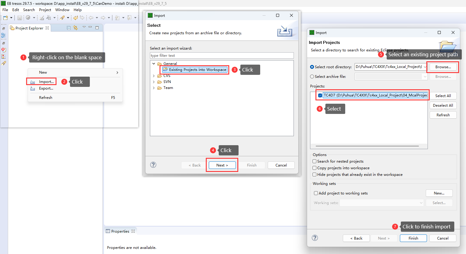
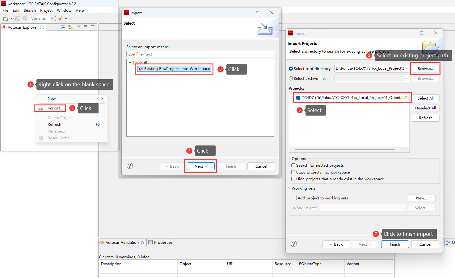
Please import the existing MCAL configuration project (04_McalProject) into EB tresos according to the following steps:
Figure 6. Importing MCAL configuration project into EB tresos diagram
Please refer to the TC4D7 user manual, development board manual, and chip manual provided by Infineon to complete the MCAL configuration, verification, and generation of the MCAL configuration file. The detailed configuration process will not be explained here.
For usage of the MCAL configuration tool, please consult the EB tresos manual.
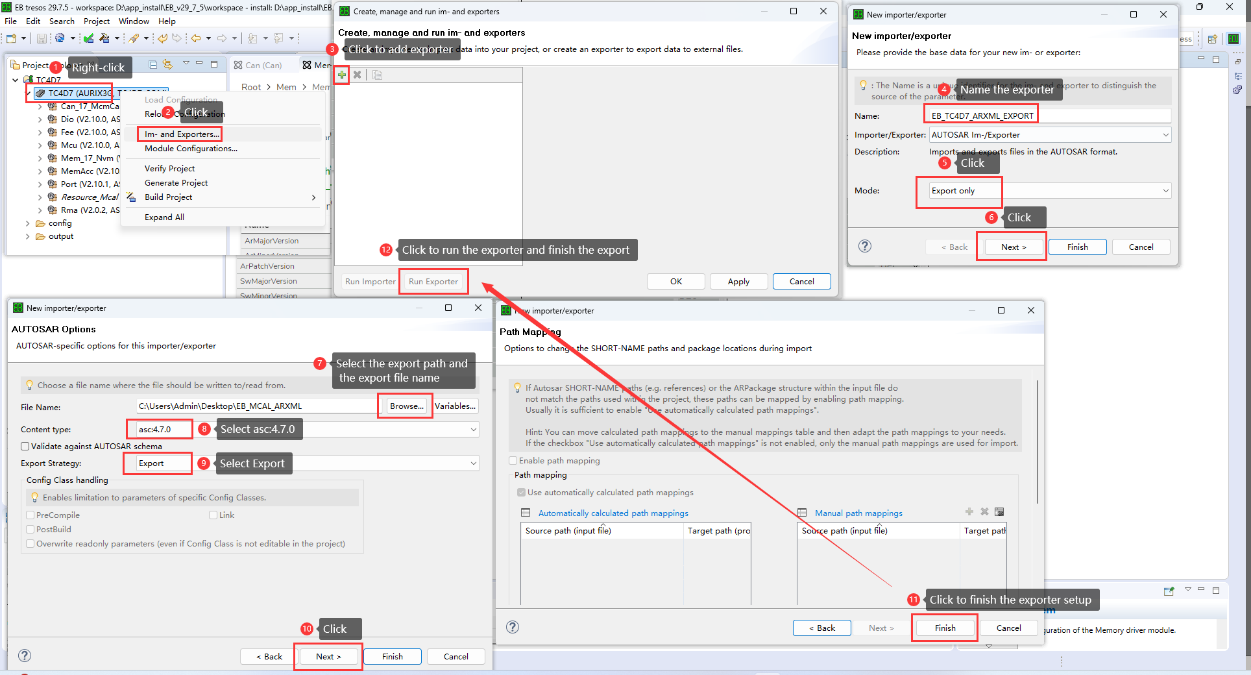
After completing the MCAL configuration, export it in ARXML format. The export flow is illustrated below:
Figure 7. EB tresos export MCAL configuration diagram
Configure SWC
For usage of SWC Builder, refer to:
ORIENTAIS_SWC_Builder_2.0_User_Manual_Software_Design.pdf
ORIENTAIS_SWC_Builder_2.0_User_Manual_Overview.pdf
ORIENTAIS_SWC_Builder_2.0_User_Manual_Feature.pdf
Location: ..
..\iSOFT\Tool_User_Manual\ ORIENTAIS_SWC_Builder_2.0_User_Manual_Software_Design.pdf
..\iSOFT\Tool_User_Manual\ORIENTAIS_SWC_Builder_2.0_User_Manual_Overview.pdf
..\iSOFT\Tool_User_Manual\ ORIENTAIS_SWC_Builder_2.0_User_Manual_Feature.pdf
The license key for the tool is given in your Infineon Developer Center (lDC) portal
(Ensure to login to IDC using registered credentials).
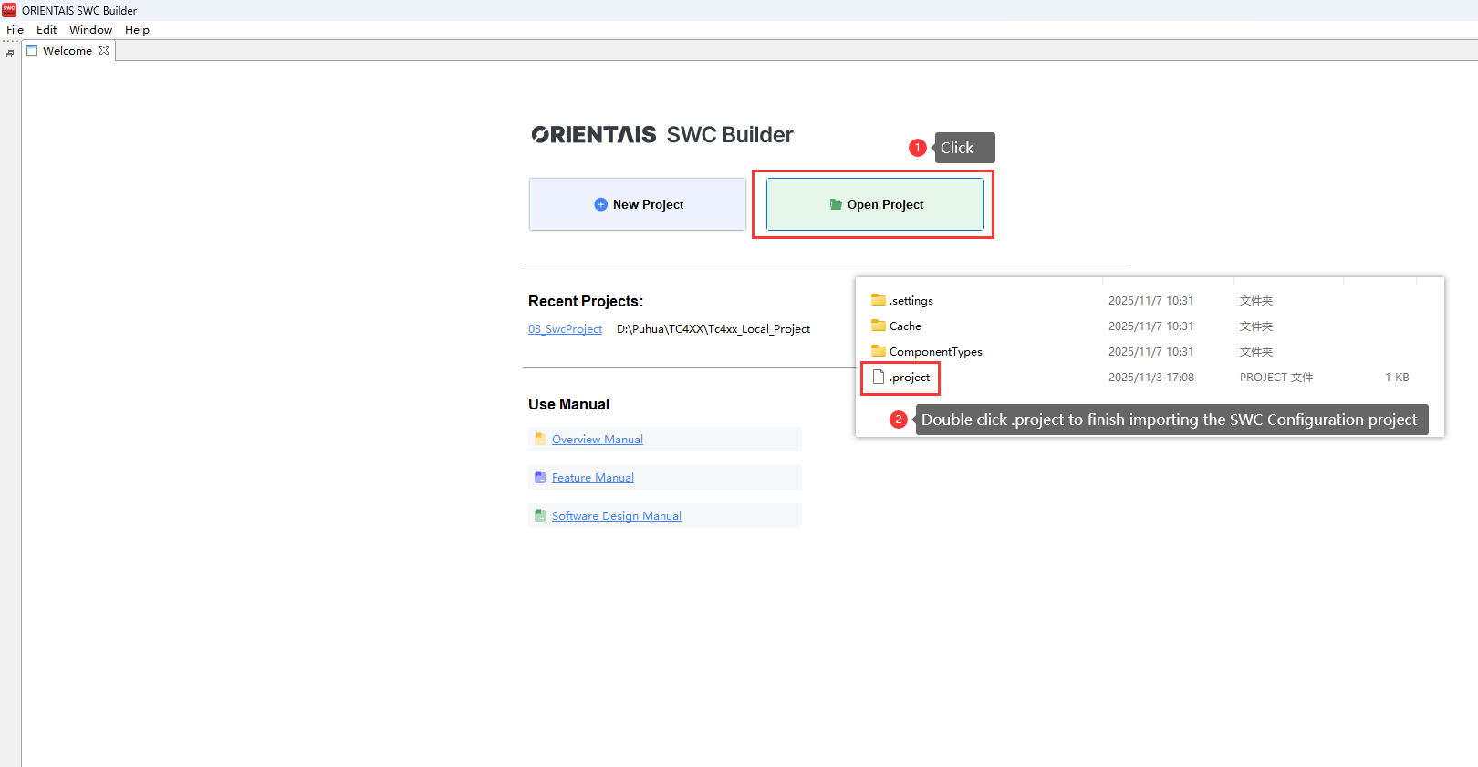
Please import the existing SWC configuration project (03_SwcProject) into ORIENTAIS_SWC_Builder according to the following steps:
Figure 8. Importing SWC configuration project into SWC tool diagram
The SWC is used to configure the Service Encapsulation Interface. Please configure it according to specific requirements. For usage of the SWC configuration tool, refer to the
ORIENTAIS_SWC_Builder_2.0_Feature_Manual.pdf
(It is located in the installation directory usermanual of the SWC configuration tool).
Import the DBC file into the SWC configuration tool
Complete the SWC configuration
Perform ECU extraction
Import the resulting extraction file (in ARXML format) into the BSW configuration tool;
Importing the DBC file into the SWC configuration tool is shown in the diagram below:
Figure 9. Importing DBC file into SWC tool diagram
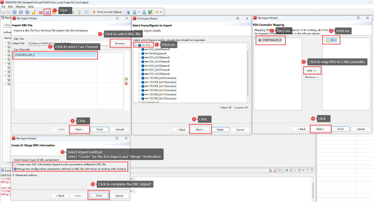
Below is the description of the imported CAN communication matrix:
Message Name | ID | Description |
|---|---|---|
ECU_0x100 | 0x100 | Periodic message, cycle time:100 ms |
ECU_0x101 | 0x101 | Mixed message, normal period 1000 ms, after event trigger send 3 consecutive frames with 50 ms interval |
ECU_0x102 | 0x102 | Event message, after trigger send 4 consecutive frames with 50 ms interval |
ECU_0x103 | 0x103 | Event message |
ECU_0x104 | 0x104 | Event message |
ECU_0x200 | 0x200 | Event message |
Message Name | ID | Description |
|---|---|---|
TESTER_0x110 | 0x110 | Periodic message, cycle time:100 ms |
TESTER_0x111 | 0x111 | Periodic message, cycle time:100 ms |
TESTER_0x112 | 0x112 | Periodic message, cycle time:100 ms |
TESTER_0x113 | 0x113 | Periodic message, cycle time:100 ms |
TESTER_0x114 | 0x114 | Periodic message, cycle time:100 ms |
TESTER_0x201 | 0x201 | Normal message |
Before performing the extraction export, need to configure either inter-ECU or intra-ECU communication (Sender-Receiver communication) so that the CAN communication matrix imported from the DBC file can be extracted correctly.
This project implements a 1:N communication mechanism using the multi-instance approach, creating one sender and three receivers. The procedure is as follows:
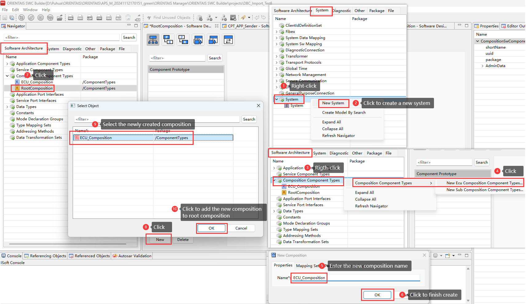
Create one System and one ECU Composition, then add the ECU Composition to the Root Composition, as shown in the diagram below:
Figure 10.
Inter-ECU communication configuration diagram 1
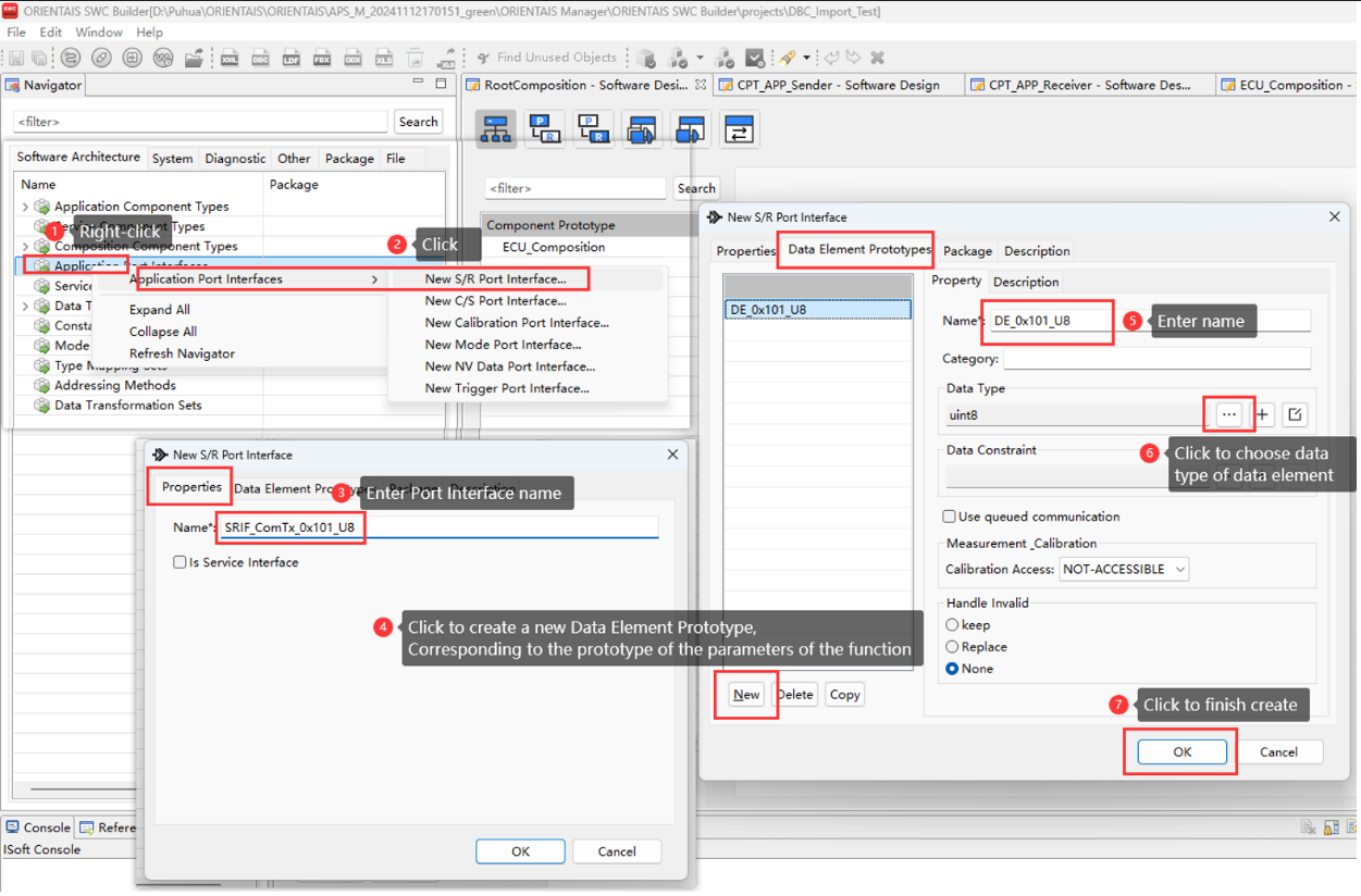
A SWC’s externally visible behavior is defined by its Ports and Port Interfaces. A Port is a concrete communication endpoint of the SWC; each Port is bound to exactly one Port Interface through which data items are exchanged or services are invoked. For this project two Port Interfaces are created:
one for the Sender
one for the Receiver
Figure 11.
Inter-ECU communication configuration diagram 2
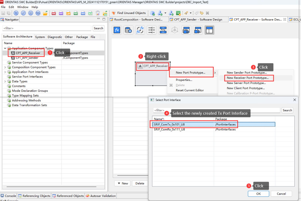
Create two application components Sender and Receiver:
The Sender instantiates one Provide-type Port Prototype (bound to the Provide Port Interface)
The Receiver instantiates one Receive-type Port Prototype (bound to the Receive Port Interface)
Figure 12.
Inter-ECU communication configuration diagram 3
Each of the two application SWCs creates one cyclic Runnable, as shown below:
Figure 13.
Inter-ECU communication configuration diagram 4
Create one Access-Point Trigger for each runnable:
Sender runnable - select Write Data
Receiver runnable - select Read Data
Figure 14.
Inter-ECU communication configuration diagram 5
For the ECU Composition created in Step 1, create four Port prototypes:
three R-Ports (Receiver)
one P-Port (Provider)
Note:
Each new Port prototype is bound to the corresponding Port Prototype created in Step 3, the three R-Ports all use the same Receive-type Port Prototype, as shown in the diagram below:
Figure 15.
Inter-ECU communication configuration diagram 6
Create four delegation ports and bind each one to the corresponding Port prototype created in Step 6. For every delegation port, add an Inter Port connection that links the delegation port to the application component’s port, as shown in the diagram below:
Figure 16.
Inter-ECU communication configuration diagram 7
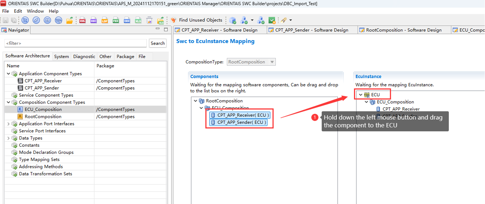
Map the application components to the ECU, as shown in the diagram below:
Figure 17.
Inter-ECU communication configuration diagram 8
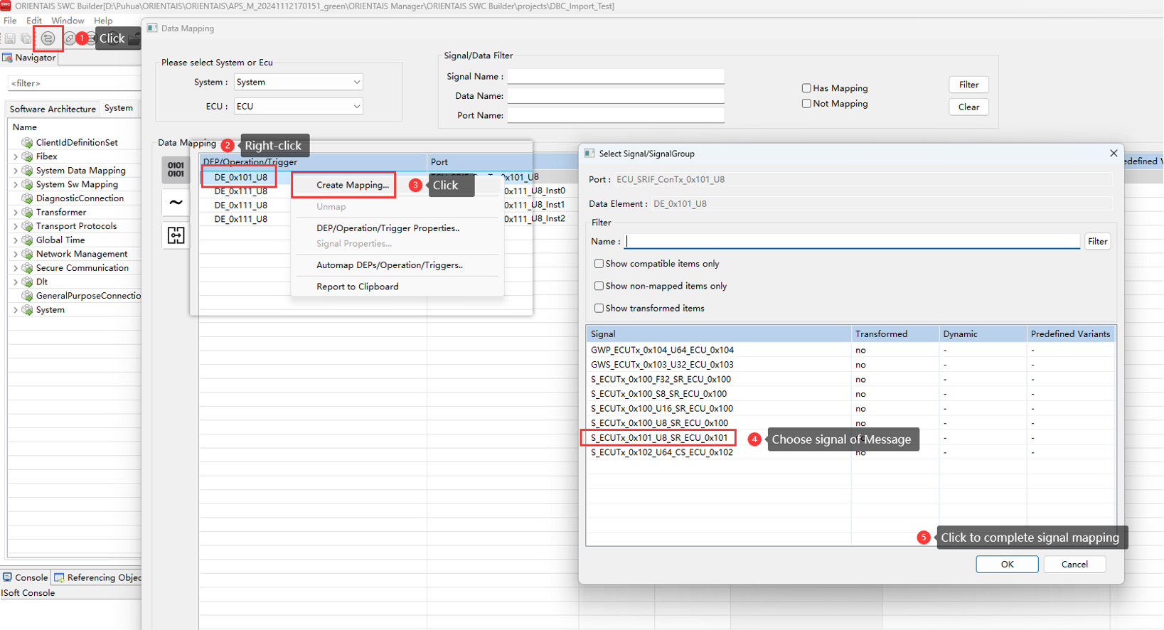
Signal mapping links the Sender-Receiver communication data to message signals, in this project, to the signals carried on the CAN frames, as shown in the diagram below:
Figure 18.
Inter-ECU communication configuration diagram 9
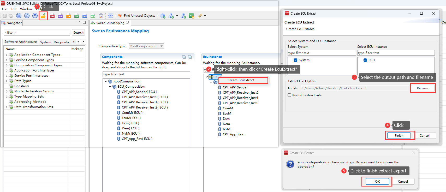
After the Sender-Receiver communication configuration above is complete, perform the ECU extraction, as shown in the diagram below:
Figure 19. SWC configuration tool exporting extraction file diagram
Configure BSW
For usage of BSW Configurator, refer to ORIENTAIS_Configurator_V2.2_User_Manual.pdf
Location:
..\iSOFT\Tool_User_Manual\ORIENTAIS_Configurator_V2.2_User_Manual.pdf
The license key for the tool is given in your Infineon Developer Center (lDC) portal
(Ensure to login to IDC using registered credentials).
Please import the existing BSW configuration project (01_OrientaisProject) into ORIENTAIS_Configurator according to the following steps:
Figure 20. Importing BSW configuration project into BSW configuration tool diagram
This project configures 18 messages in total: twelve for CAN communication (periodic, event and mixed), one for CAN network management, three for CAN diagnostic communication and two for E2E communication. A total of 10 Tasks are configured.
For detailed BSW configuration, please refer to
Configuration
. For instructions on using the BSW configuration files, please refer to
ORIENTAIS_Configurator_V2.2_User_Manual.pdf
(It is located in the installation directory usermanual of the BSW configuration tool).
After finishing the MCAL configuration, import the MCAL configuration file (ARXML) exported by
Configure MCAL
into the BSW configuration tool. This step is required because BSW modules depend on the MCAL settings, the import flow is as follows:
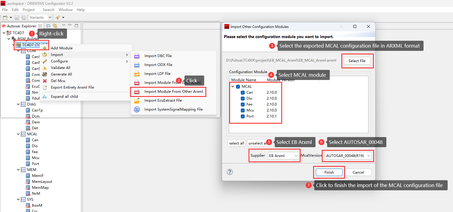
Figure 21. BSW configuration tool importing MCAL configuration diagram
After SWC configuration is complete, import the ECU extract file (ARXML) exported by
Configure SWC
into the BSW configuration tool, this import is necessary because SWC configuration essentially links user interfaces with BSW interfaces, the import flow is as follows:
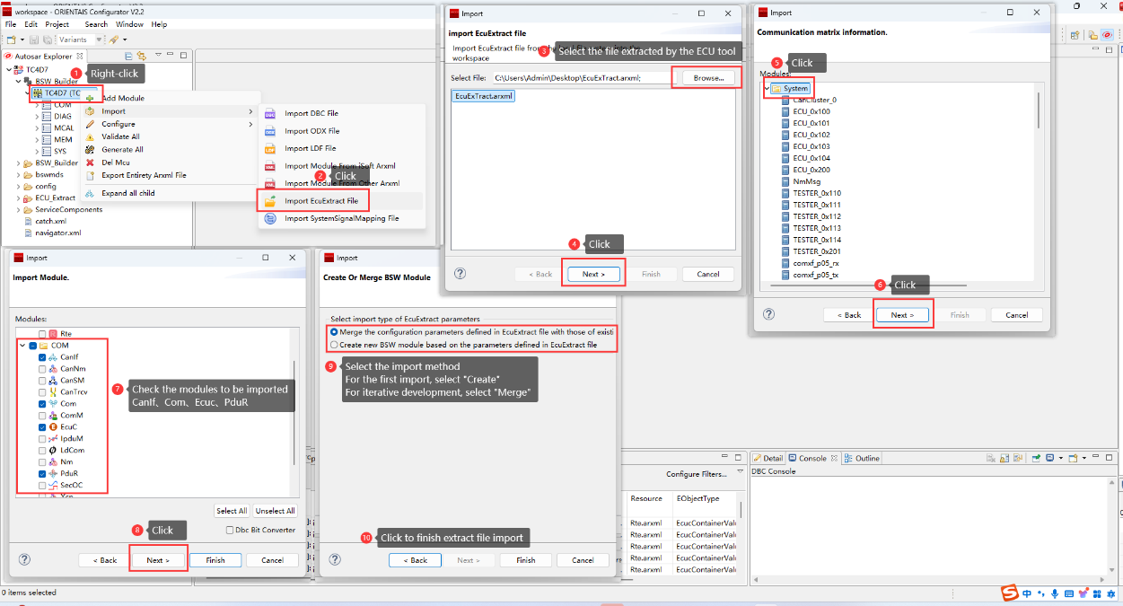
Figure 22. BSW configuration tool importing extract file diagram
After MCAL and SWC configuration are complete, configure the BSW modules according to
Configuration
, then generate the configuration by following the steps below:
Configure the initialization configuration of each module inside EcuM
Figure 23.
EcuM configuration diagram 1
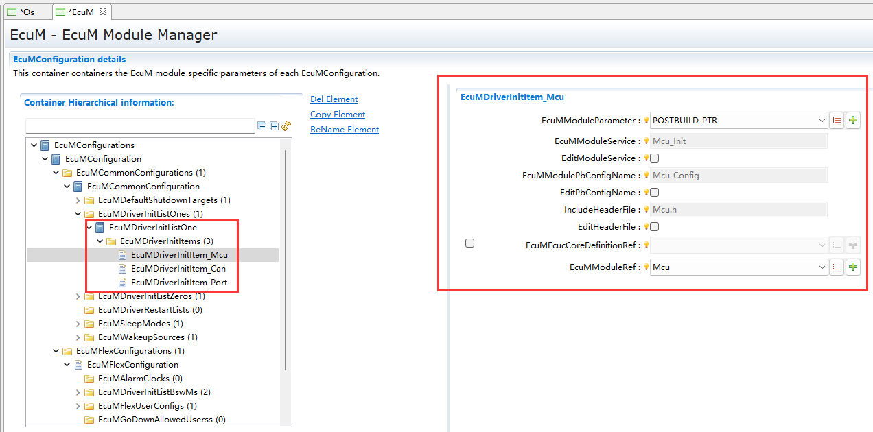
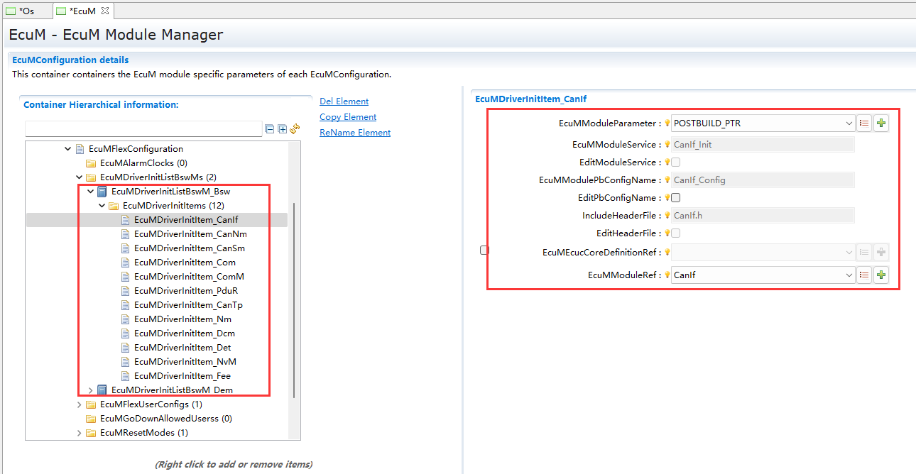
Figure 24.
EcuM configuration diagram 2
Update the Bswmd files of all BSW modules, re-synchronise Rte/iRte-OS, open the OS module and save it, so that every BSW MainFunction is dispatched by the correct Task
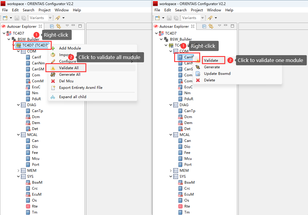
Validate all BSW modules and resolve every error. Choose to validate all modules at once or one module at a time. Refer to the diagram below, the left half diagram shows the simultaneous validation of all modules, the right half diagram shows the validation of a single module
Figure 25.
BSW configuration tool validation diagram
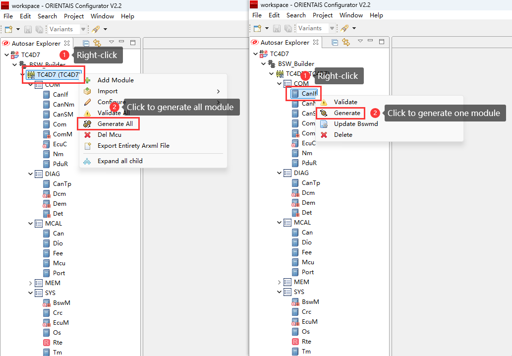
Generate configuration files for all BSW modules, choose to generate all modules at once or one module at a time. The left half of the diagram shows the generate all modules, the right half of the diagram shows the generate single module
Figure 26.
BSW configuration tool generation diagram
Only on the first generation, add the CAN interrupt-service functions to the corresponding ISR entry points in the generated Os_UserInf.c, this ensures the correct routine is invoked when the interrupt occurs. In all subsequent generations the previously added code will be preserved and not overwritten, as illustrated below
ISR(ISR_CAN0_INT4_Handler)

{

/* please insert your code here ... */

/** DO NOT CHANGE THIS COMMENT!

* <USERBLOCK CAN0_INT4>

*/

/* custom code.... */

Can_17_McmCan_IsrReceiveHandler(0,1);

/** DO NOT CHANGE THIS COMMENT!

* </USERBLOCK>

*/

}

ISR(ISR_CAN0_INT5_Handler)

{

/* please insert your code here ... */

/** DO NOT CHANGE THIS COMMENT!

* <USERBLOCK CAN0_INT5>

*/

/* custom code.... */

Can_17_McmCan_IsrTransmitHandler(0,1);

/** DO NOT CHANGE THIS COMMENT!

* </USERBLOCK>

*/

}

ISR(ISR_CAN0_INT6_Handler)

{

/* please insert your code here ... */

/** DO NOT CHANGE THIS COMMENT!

* <USERBLOCK CAN0_INT6>

*/

/* custom code.... */

Can_17_McmCan_IsrBusOffHandler(0,1);

/** DO NOT CHANGE THIS COMMENT!

* </USERBLOCK>

*/

}

ISR(ISR_CAN0_INT7_Handler)

{

/* please insert your code here ... */

/** DO NOT CHANGE THIS COMMENT!

* <USERBLOCK CAN0_INT7>

*/

/* custom code.... */

Can_17_McmCan_IsrRxFIFOHandler(0,1);

/** DO NOT CHANGE THIS COMMENT!

* </USERBLOCK>

*/

}
After every generation, place MemAcc_MainFunction() and Mem_17_Nvm_MainFunction() immediately after Fee_MainFunction() in the generated Rte.c to ensure the memory stack MainFunctions are dispatched in the correct order, as shown below
TASK(iSoft_Auto_OsTask_10ms_BSW)

{

EventMaskType eventMask;/* PRQA S 1532 */ /*VL_QAC_OneFunRef */

while (1)

{

WaitEvent(iSoft_Auto_OsEvent_10ms_BSW);

GetEvent(iSoft_Auto_OsTask_10ms_BSW,&eventMask);

ClearEvent(eventMask);

/* Position:0 */

if ((eventMask & iSoft_Auto_OsEvent_10ms_BSW) != 0)

{

Fee_MainFunction();

MemAcc_MainFunction();

Mem_17_Nvm_MainFunction();

}

}

}
Modify Cpu0_Main.c, place EcuM_Init() inside core0_main() and use it to perform ECU initialization, as shown below
#include "EcuM.h"

void core0_main (void)

{

EcuM_Init();

for(;;)

{

}

}
Place Mcu_Init() in EcuM_Callout_Stubs.c and initialize the clocks(Initialization clock options, lock the PLL, and switch the clock source), as shown below
void EcuM_AL_DriverInitOne(void)

/* PRQA S 6070 -- */

{

const EcuM_GenBSWPbCfgType * pbCfg =EcuM_ConfigPtr->modulePBCfg;

/* PRQA S 0317 ++ */ /* VL_QAC_0317 */

/** DO NOT CHANGE THIS COMMENT!

* <USERBLOCK EcuM_AL_DriverInitOne MCU one>

*/

/* custom code.... */

/** DO NOT CHANGE THIS COMMENT!

* </USERBLOCK>

*/

Mcu_Init(pbCfg->mcu00PbCfg);

/** DO NOT CHANGE THIS COMMENT!

* <USERBLOCK EcuM_AL_DriverInitOne MCU two>

*/

/* custom code.... */

(void)Mcu_InitClock(0);

while(MCU_PLL_UNLOCKED ==Mcu_GetPllStatus())

{

}

(void)Mcu_DistributePllClock();

/** DO NOT CHANGE THIS COMMENT!

* </USERBLOCK>

*/

Can_17_McmCan_Init(pbCfg->can01PbCfg);

Port_Init(pbCfg->port02PbCfg);

/* PRQA S 0317 -- */

/** DO NOT CHANGE THIS COMMENT!

* <USERBLOCK EcuM_AL_DriverInitOne Other>

*/

/* custom code.... */

Mem_17_Nvm_Init(NULL_PTR);

extern const MemAcc_ConfigType MemAcc_Config;

MemAcc_Init(&MemAcc_Config);

/** DO NOT CHANGE THIS COMMENT!

* </USERBLOCK>

*/

}
The iSOFT-supplied link file
Lcf_Tasking_Tricore_Tc.lsl
includes the BSW link file
Bsw_Link.lsl
and the OS link
file Os_Link.lsl
, both auto-generated when BSW configuration is generated
Configuration
CAN Communication Stack
Overview of the CAN Communication Protocol Stack
The CAN communication protocol stack involves the following software modules: CAN, CanIf, PduR, Com, and ECUC. The main function of each module is listed in the table below:
Module Name | Function |
|---|---|
Can | Configures the CAN controller, baud rate, and transmit/receive mailboxes |
CanIf | CanIf handles PDU transfer between upper layers and the CAN driver, offering a uniform interface to manage different CAN hardware |
PduR | PDU Router provides I-PDU-based routing among communication interface (CanIf), transport protocol (CanTp), diagnostic communication manager (Dcm), and communication manager (Com) |
Com | COM offers I-PDU and signal management |
Ecuc | ECUC supplies PDU definitions so all modules can reference them and be cross-linked by the configuration tool |
Configuration of the CAN Communication Protocol Stack
Configure one CAN controller (Node 1, base address 0xf4710500) with a baud rate of 500 kbps (default); set up two receive mailboxes (one standard frame, one extended frame) and one transmit mailbox (standard frame).
When the extraction file is imported, the CAN communication protocol stack automatically sets up the routing; the only additional work is to configure CanIf, since it is tied to the CAN driver. The extra CanIf settings required are listed below:
Parameter Name | Value |
CanIfCtrlCanCtrlRef | Select the CAN Controller configured in the CAN module |
CanIfCtrlDrvNameRef | Select the CAN module name (Can_17_McmCan) |
CanIfPublicCtrlDrvVersion | Select the CAN module AUTOSAR version (AUTOSAR440) |
CanIfPublicCddHeaderFile | Select the CAN module header file name (Can_17_McmCan.h) |
CAN Network Manage Protocol Stack
Overview of the CAN Network Manage Protocol Stack
Module Name | Function |
|---|---|
Can | Configures the CAN controller, baud rate, and message buffers |
CanIf | CanIf routes PDUs between upper layers and the CAN driver, offering a uniform interface to manage different CAN hardware |
NM | The Nm module acts as an adaptation layer between ComM and CanNm and coordinates synchronized shutdown across bus channels |
ComM | ComM collects and arbitrates communication requests, driving one state machine per channel to control all on-board busses |
CanSM | Interacts with the hardware-abstraction and system-service layers to define bus-specific state management and flow control for each CAN bus |
CanNM | Decides ECU state transitions (when to enter sleep, remain fully operational, etc.) |
Ecuc | ECUC provides PDU definitions so all modules can be cross-linked by the configuration tool |
Configuration of the CAN Network Manage Protocol Stack
CAN network-management transmit message ID is 0x410.
Key configuration parameters for the CAN network management stack are listed below:
Parameter Name | Value |
|---|---|
CanNmComControlEnabled | True |
CanNmMainFunctionPeriod | 0.005 |
CanNmActiveWakeupBitEnabled | True |
CanNmImmediateNmTransmissions | 0 |
CanNmMsgCycleOffset | 0.01 |
CanNmMsgCycleTime : | 0.2 |
CanNmNodeDetectionEnabled | True |
CanNmNodeId | 0 |
CanNmNodeIdEnabled | True |
CanNmPduCbvPosition | CANNM_PDU_BYTE_1 |
CanNmPduNidPosition | CANNM_PDU_BYTE_0 |
CanNmRepeatMessageTime | 1.0 |
CanNmTimeoutTime | 3.0 |
CanNmWaitBusSleepTime | 4.0 |
CanNmComMNetworkHandleRef | Reference the CAN channel configured in the ComM module. |
Parameter Name | Value |
|---|---|
CanSMMainFunctionTimePeriod | 0.002 |
CanSMModeRequestRepetitionMax | 10 |
CanSMModeRequestRepetitionTime | 0.01 |
CanSMBorCounterL1ToL2 | 20 |
CanSMBorTimeL1 | 0.01 |
CanSMBorTimeL2 | 0.1 |
CanSMBorTimeTxEnsured | 1.0 |
CanSMComMNetworkHandleRef | Reference the CAN channel configured in the ComM module |
CanSMControllerId | Reference the CAN controller ID defined in the CanIf module |
Parameter Name | Value |
|---|---|
ComMDirectUserMapping | True |
ComMEcuGroupClassification | 3 |
ComMResetAfterForcingNoComm | True |
ComMDcmEnabled | True |
Parameter Name | Value |
|---|---|
NmNumberOfChannels | 1 |
NmComControlEnabled | True |
NmPduRxIndicationEnabled | True |
NmStateChangeIndEnabled | True |
NmComMChannelRef | Reference the CAN channel configured by ComM |
NmStandardBusType | NM_BUSNM_CANNM |
CAN Diagnostic Protocol Stack
Overview of the CAN Diagnostic Protocol Stack
Module Name | Function |
|---|---|
Can | Configures the CAN controller, baud rate, and message buffers |
CanIf | CanIf routes PDUs between upper layers and the CAN driver, giving them a single interface to manage any CAN hardware |
PduR | PDU Router routes I-PDUs among the communication interface (CanIf), transport protocol (CanTp), diagnostic communication manager (Dcm), and communication manager (Com) |
CanTp | CanTp implements the ISO 15765-2 transport layer send/receive service on CAN |
Dcm | Parses diagnostic requests and executes positive/negative responses according ISO 15765-3 and ISO 14229-1 |
Dem | Implements storage and management of diagnostic faults, and provides APIs for other modules to read DTCs along with their associated freeze-frame and extended data |
Configuration of the CAN Diagnostic Protocol Stack
CAN IDs for the CAN diagnostic protocol stack are listed below:
CANID Type | CANID |
|---|---|
Physical Request CAN ID | 0x703 |
Functional Request CAN ID | 0x7DF |
Physical Response CAN ID | 0x70A |
Diagnostic services configured in the project are listed below:
Service ID | Diagnostic Services Name | Sub-functions | Diagnostic Session | NRCApplies | Security Level | |||
|---|---|---|---|---|---|---|---|---|
Default(01) | Extended(03) | |||||||
Phy | Func | Phy | Func | Level 1 | ||||
0x10 | DiagnosticSessionControl | 0x01 DefaultSession | √ | √ | √ | √ | 12 13 22 7E | |
0x02 ProgrammingSession | × | × | √ | √ | ||||
0x03 ExtendedDiagnosticSession | √ | √ | √ | √ | ||||
0x11 | EcuReset | 0x01 HardReset | × | × | √ | × | 12 13 22 7F | |
0x27 | SecurityAccess | 0x01 Security Level1 (Request Seed) 0x02 Security Level1 (Send Key) | × | × | √ | × | 12 13 22 24 31 35 36 37 7F | |
0x28 | CommunicationControl | 0x00 EnableRxAndTx | × | × | √ | √ | 12 13 22 31 7F | |
0x01 EnableRxAndDisableTx | × | × | √ | √ | ||||
0x02 DisableRxAndEnableTx | × | × | √ | √ | ||||
0x03 DisableRxAndTx | × | × | √ | √ | ||||
0x3E | TesterPresent | 0x00 ZeroSubFunction | √ | √ | √ | √ | 12 13 | |
0x85 | ControlDTCSetting | 0x01 ON | × | × | √ | √ | 12 13 22 31 | |
0x02 OFF | × | × | √ | √ | ||||
0x22 | ReadDataByIdentifier | N/A | √ | √ | √ | √ | 13 22 31 | |
0x2E | WriteDataByIdentifier | N/A | × | × | √ | × | 13 31 22 7F | √ |
0x14 | ClearDiagnosticInformation | FFFFFF - Clear All DTCs | × | × | √ | × | 13 22 31 7F | |
0x19 | ReadDTCInformation | 0x01 ReportNumberOfDTCByStatusMask | × | × | √ | × | 12 13 31 7F | |
0x02 ReportDTCByStatusMask | × | × | √ | × | ||||
0x04 ReportDTCSnapshotRecordByDTCNumber | × | × | √ | × | ||||
0x06 ReportDTCExtendedDataRecordByDTCNumber | × | × | √ | × | ||||
0x0A ReportSupportedDTC | × | × | √ | × | ||||
0x2F | InputOutputControlByIdentifier | N/A | × | × | √ | × | 13 22 31 33 7F | √ |
0x31 | RoutineControl | 0x01 StartRoutine | × | × | √ | × | 12 13 22 24 31 33 | √ |
0x02 StopRoutine | × | × | √ | × | ||||
0x03 RequestRoutineResults | × | × | √ | × | ||||
Configuration information of the security access algorithm is as follows:
Mask = 0x5555AAAAu |
The key algorithm (calculating the key based on the seed) is as follows, where 'seed' refers to the input seed.
Key = Seed & Mask |
Note:
The maximum number of failed attempts is 3; once this limit is reached, a 10-second delay is triggered. Consecutive invalid seed requests do not increment the error count. If the seed remains unchanged, the error count will reset to zero after the delay period expires.
DIDs(HEX) | Name | InputOutputControlParameter | ControlOption | ControlStatus | Size(Byte) |
|---|---|---|---|---|---|
1111 | 00 | × | √ | 1 | |
01 | × | √ | 1 | ||
02 | × | √ | 1 | ||
03 | √ | √ | 1 |
Note:
InputOutputControlParameter: This parameter is used in the request message of &2F service to describe how the server shall control its inputs or outputs
ControlOption: This parameter is used in the request message of $2F service to describe the detailed control state of request
ControlState: This parameter is used in the response message of $2F service to describe the detailed control results
DIDs(HEX) | Name | InputOutputControlParameter | ControlOption | ControlStatus | Size(Byte) |
|---|---|---|---|---|---|
F183 | Sw number | √ | 300 | ||
F184 | √ | √ | 9 | ||
1111 | √ | √ | √ | 1 | |
F198 | √ | 6 | |||
F298 | √ | 1 | |||
F286 | √ | 100 | |||
F170 | Used for DID–NVM interaction validation | √ | √ | 10 |
DIDs | Name | RoutineControlType | RoutineControlOption | RoutineStatus | in Size | out size | Safety level requirements |
|---|---|---|---|---|---|---|---|
0x1234 | 01 | √ | √ | 1 | 1 | LevWel1 | |
02 | √ | √ | 1 | 1 | |||
03 | √ | 0 | 1 | ||||
0x0203 | CheckProgPreCondition | 01 | √ | 0 | 1 | Level1 |
Note:
RoutineControlType: 01: startRoutine, 02: stopRoutine, 03: requestRoutineResults
RoutineControlOption: This parameter is used in the request message of $31 service to describe the detailed control state of request
RoutineStatus: This parameter is used in the response message of $31 service to describe the detailed control results
DTC Number | DTC Description | DTC-Set Condition | Faults-Recover Condition | W/Lamp | Possible Fault Causes | Corrective Actio |
|---|---|---|---|---|---|---|
0xC00001 | The test code causes SWC to report faults | SWC directly reports faults | SWC reports non-fault | No | SWC directly reports faults | |
0xC00002 | The test code causes SWC to report faults | SWC directly reports faults | SWC reports non-fault | No | SWC directly reports faults | |
0xC00003 | The test code causes SWC to report faults | SWC directly reports faults | SWC reports non-fault | Yes | SWC directly reports faults | |
0xC00004 | The test code causes SWC to report faults | SWC directly reports faults | SWC reports non-fault | Yes | SWC directly reports faults | |
0xC00005 | CAN Bus off | CAN Bus off | CAN not in busoff state | No | 1: CAN connect line failure 2: controller failure | 1: check connect line 2: change RM controller |
Table 20 DTC Attribute table
DTC Number | EventId | Debounce Algorithm | WIR Information | Debounce Threshold | Aging Threshold | DTC priority |
|---|---|---|---|---|---|---|
0xC00001 | 1 | counter | 10 | 5 | 1 |
Tip:
The Tester through seed DTC Status 0x01 read only the currently DTC, through seed DTC Status 0x08 read only the history DTC. All the ECU should obey it.
Memory Protocol Stack
Overview of the Memory Protocol Stack
Module Name | Function |
|---|---|
Mem | Offers upper layers a unified, hardware-independent read/write/erase interface |
MemAcc | Exposes address-based parameters, letting upper modules access diverse memory devices |
Fee | Provides a virtual linear address space and a common allocation scheme |
MemIf | Bridges NvM to Fee |
NvM | Stores and manages non-volatile data |
Configuration of the Memory Protocol Stack
The memory stack is configured with the following NvM blocks:
NvMBlock Name | Function |
|---|---|
NvMBlock_ConfigID | NVM management |
NvMBlock_DID_0xF170 | Stores DID 0xF170 data |
NvMBlock_FalseAccessCount | Records unsuccessful 0x27 unlock attempts |
NvMBlock_Primary_0 | Stores event data |
NvMBlock_Primary_1 | Stores event data |
NvMBlock_Primary_2 | Stores event data |
NvMBlock_Primary_3 | Stores event data |
NvMBlock_Primary_4 | Stores event data |
NvMBlock_AdminData | Stores DEM management data |
NvMBlock_EventStatusData | Stores UDS status |
Os protocol Stack
Overview of the Os protocol Stack
AUTOSAR OS is responsible for task and interrupt management, implementing modules such as Task, ISR, Counter, Alarm, ScheduleTable, Event, and Resource.
Configuration of the Os protocol Stack
Most of the OS stack configuration is completed automatically by synchronizing Rte/iRte-Os; only the compiler environment, system clock frequency and Oslsrs (interrupt service routines) must be set manually.
The following OS configuration items have been completed:
Name | Value |
|---|---|
Cores Number | 1 |
Compiler | tasking_cctc |
Name | Parameter | Value |
|---|---|---|
OsTimerSourceCore_0 | STM_Frequency[MHz] | 100 |
OsTimerSourceCore_0 | TickTime[s] | 0.001 |
OsTimerSourceCore_0 | Stack Size[4bytes] | 512 |
Name | Gategory | Stack Size[4Bytes] | Priority | Nested Enable | Core |
|---|---|---|---|---|---|
CAN0_INT4 | GATEGORY_2 | 512 | 4 | False | 0 |
CAN0_INT5 | GATEGORY_2 | 512 | 5 | False | 0 |
CAN0_INT6 | GATEGORY_2 | 512 | 6 | False | 0 |
CAN0_INT7 | GATEGORY_2 | 512 | 7 | False | 0 |
Name | Priority | Stack Size[4Bytes] | Preemptive Poilcy | OsTaskAutostart | Core |
|---|---|---|---|---|---|
iSoft_Auto_OsTask_1ms | 25 | 256 | FULL | False | 0 |
iSoft_Auto_OsTask_10ms | 25 | 256 | FULL | False | 0 |
iSoft_Auto_OsTask_19ms | 25 | 256 | FULL | False | 0 |
iSoft_Auto_OsTask_Shared_0 | 63 | 256 | FULL | False | 0 |
iSoft_Auto_OsTask_2ms_BSW | 25 | 256 | FULL | False | 0 |
iSoft_Auto_OsTask_5ms_BSW | 25 | 256 | FULL | False | 0 |
iSoft_Auto_OsTask_10ms_BSW | 25 | 256 | FULL | False | 0 |
iSoft_Auto_OsTask_20ms_BSW | 25 | 256 | FULL | False | 0 |
iSoft_Auto_OsTask_SchM_0 | 63 | 256 | FULL | False | 0 |
iSoft_Auto_DEFAULT_OsTask_Init | 63 | 1024 | NON | False | 0 |
Running the demo or build
Build and download
TASKING_SmartCode_v10.3r1 installation excute file location:
..\Tasking\ TASKING_SmartCode_v10.3r1.zip
For the installation of the TASKING Smartcode, please refer to the following documentation:
..\Tasking\TASKING SmartCode Installation guide.pdf
For the usage of of the TASKING Smartcode, please refer to the following documentation:
..\Tasking\smartcode_ctc_user_guide.pdf
..\Tasking\smartcode_getting_started.pdf
The license key for the tool is given in your Infineon Developer Center (lDC) portal
(Ensure to login to IDC using registered credentials).
Please import the existing compilation project (02_TaskingProject) into SmartCode Eclipse IDE according to the following steps:
Figure 27. Importing compilation project into SmartCode Eclipse IDE diagram
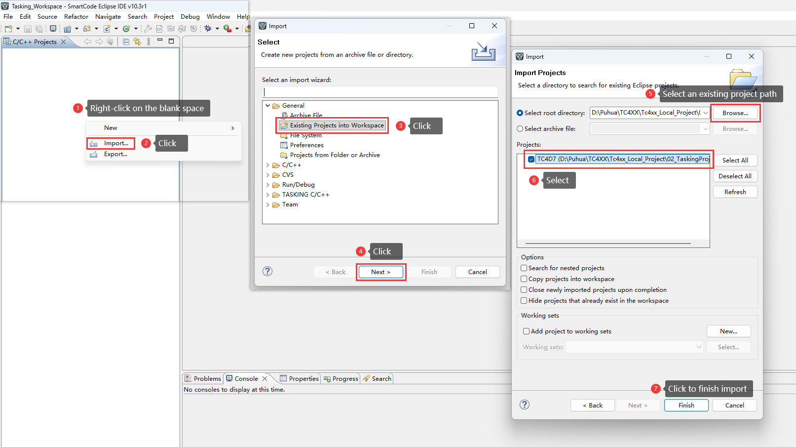
Import the code and configurtion file of MCAL, the code and configuration file of BSW, and the system-related files into the 02_TaskingProject build project, organizing them according to Figure
Configure include paths and build parameters;
Compile, first Clean project, then Build project, as shown below:
Figure 28.
Tasking project compilation diagram
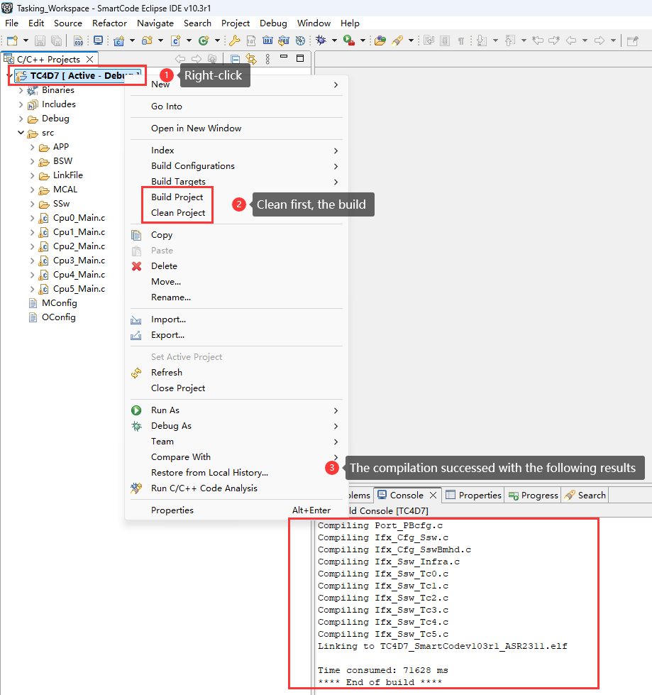
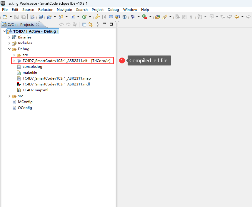
After successful compilation, the.elf file is generated in the Debug director:
Figure 29.
Compiled .elf file location diagram
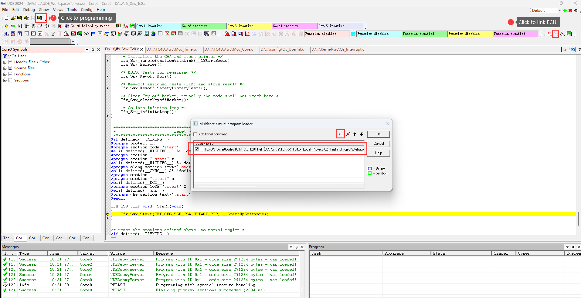
Use UDE 2024 to download the compiled .elf file into TC4D7
For usage of UDE, please refer to the official website of PLS:
https://www.pls-mc.com/support/downloads/
Note:
Users can choose other compatible devices for flashing and debugging.
Once the Universal Access Device 2pro has successfully connected the host to the ECU, downloading can proceed, as shown below:
Figure 30. UDE download diagram
Run and Verify
Verify of CAN Communication Stack
After successful download and execution, use a CAN bus debugger to receive the messages sent by theTC4D7, the following messages can be received:
Figure 31. CAN communication stack CAN bus message monitor diagram

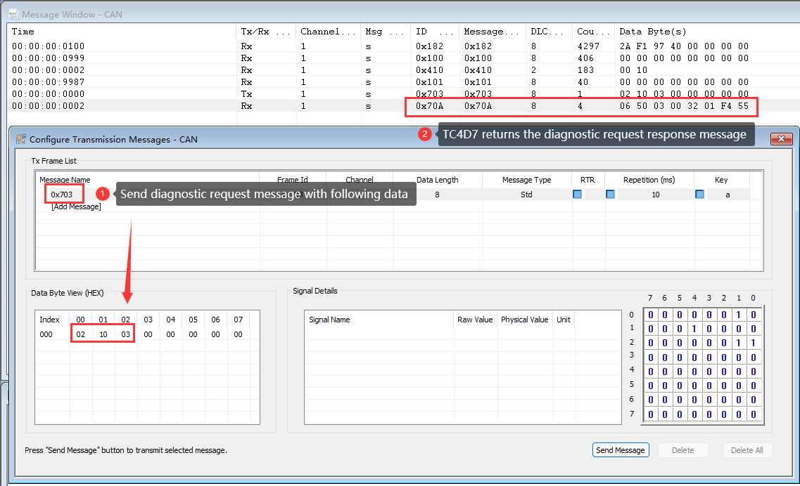
Verify of CAN Diagnostic Stack
After successful download and execution, Send a diagnostic request message (CAN ID is 0x703) to TC4D7, and TC4D7 will return a diagnostic request response message (CAN ID is 0x70A).
Figure 32. CAN diagnostic stack CAN bus message monitor diagram
Development resources
TASKING SmartCode Eclipse IDE
TASKING® SmartCode is an innovative development solution for the Infineon® AURIX™ TC4x microcontroller family. SmartCode offers reliable code optimization, advanced multicore support and fully supports all architectures and microprocessor cores integrated in the TC4x.
Universal Debug Engine
The Universal Debug Engine (UDE) is a professional debugging framework designed for multi-core SoCs (System-on-Chips) and microcontrollers. It provides a comprehensive set of tools for debugging, tracing, and testing embedded systems, offering support for both high-level languages (C/C++) and assembly-level debugging.
iSOFT ORIENTAIS_Configurator
iSOFT’s AUTOSAR solution provides a standardized,localized basic software platform for automotive electronics, supporting the development of high-performance and high-safety automotive ECUs. ORIENTAIS_Configurator is used for configuring BSW.
iSOFT ORIENTAIS_SWC_Builder
iSOFT’s AUTOSAR solution provides a standardized, localized basic software platform for automotive electronics, supporting the development of high-performance and high-safety automotive ECUs. ORIENTAIS_Configurator is used for configuring SWC.
Infineon AURIX_TC4x_MC-ISAR
Microcontroller – Infineon Software Architecture (MC-ISAR) is the AUTOSAR-compliant low-level driver for Infineon microcontrollers, also called MCAL (Microcontroller Abstraction Layer). It is the bottom layer in the AUTOSAR software architecture, interfacing directly with the hardware. It abstracts the hardware by allowing higher software layers to interface with microcontroller peripherals without having to know the peripheral’s architecture and registers.
BUSMASTER
BUSMASTER is an Open Source Software tool to Simulate, Analyze and Test data bus systems such as CAN, LIN.
Support
Troubleshooting
Module not loaded
Description
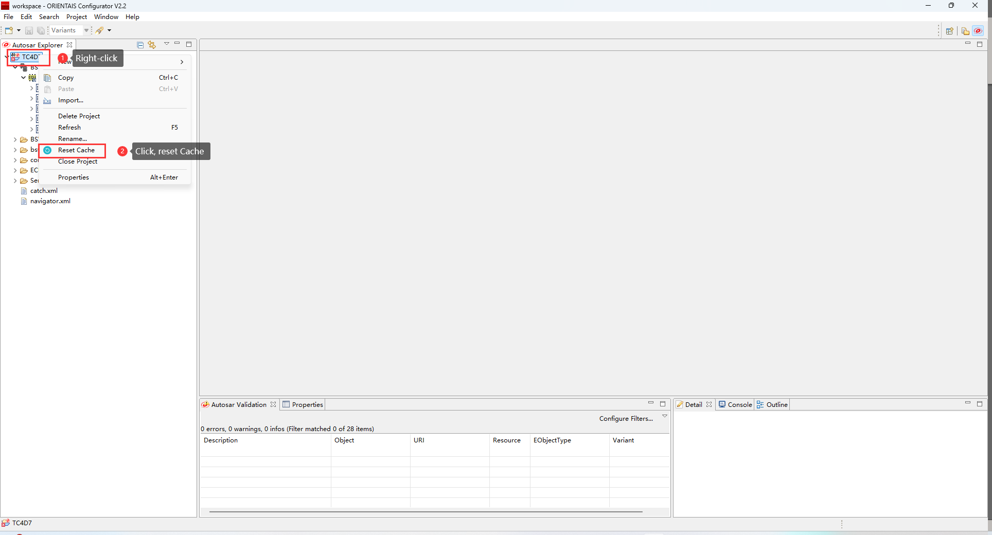
When opening an existing BSW project with the BSW configuration tool, the project cannot read the chip or module normally.
Solution
First, right-click the project button, and then click Reset Cache to reload the project.
Figure 33. Reload the project diagram
Open BSW project
Description
The BSW Configuration Tool cannot load projects with the same name simultaneously.
Solution
First, remove the project names with the same name from the workspace of the BSW configuration tool, and then open the remaining projects with the same name.
Ecu extraction
Description
The DBC file is imported into the SWC Configuration tool for direct extraction. After successful extraction, the extracted file is imported into the BSW configuration project, and the CAN protocol stack route is not automatically generated.
Solution
The signals contained in the DBC communication matrix imported by the SWC configuration tool must be used by the system to be successfully extracted. So after importing the DBC file with the SWC configuration tool, configure the communication between application components so that the signal can be used by the system.
Contact support
MyCases
In the event of any problems, issues, or questions, please do not hesitate to reach out to your designated Infineon contact or Field Application Engineer (FAE) for assistance. Alternatively, you can also submit a request through our ticketing system
. For more information on how to use the myCases portal, please refer to this
document
.
Partners
By contacting support, you agree that your request and contact details are shared between
iSOFT
,
TASKING
, and Infineon.