GAP Settings tab (Option2, Option3, Option4)
The
GAP Settings
tab parameters define the general connection settings required when connecting Bluetooth® devices. Select an item in the tree to see the various sections of parameters.
In the
General
tab, select the
GAP role
to display the
GAP Settings
tab settings. Use the
Restore Defaults
button to restore the default settings of the active tree item.
Note:
Values of many parameter settings can be customized. Also, many parameters have check boxes to enable or disable them.
The following sections describe the different categories of parameters based on the item selected in the tree.
Toolbar (GAP Settings)
The toolbar contains options to add or delete
GAP role
configuration and
Security configuration
.
Add
(
Option4
)) – Allows adding: Peripheral, Central, Broadcaster, Observer or Security configurations.
Note:
The available options depend on the GAP role selected in theGeneraltab. You can add several configurations for one GAP role and switch between them using the firmware.
Delete
(
Option4
)) – Deletes the selected Configuration.
GAP Settings tab General
This General section contains general GAP parameters.
Option2
,
Option3
, and
Option4
have different sets of parameters.
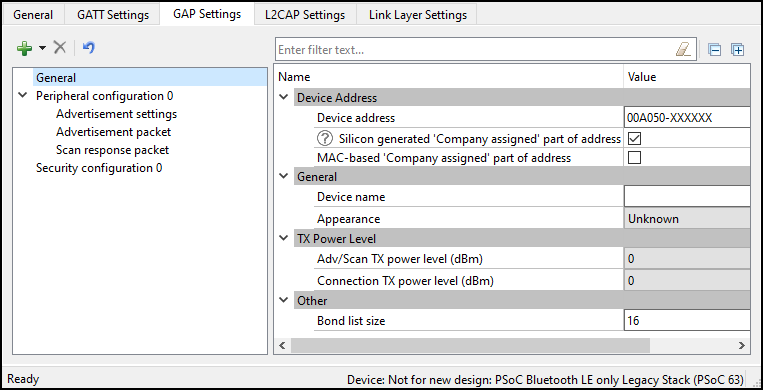
Option4
Option2, Option3
Device Address
This is a unique 48-bit Bluetooth® public address used to identify the device. It is divided into two parts:
Company ID
– The 24 most significant bits: a 24-bit Organization Unique Identifier (OUI) address assigned by IEEE.
Company assigned
– The 24 least-significant bits.
The address configured here is static and designed for development purposes only.
Note:
ForOption4, during production, the device address is programmed into the user area of the supervisory flash (Sflash) location for the device address (Row 0) via the SWD interface. Normally, this address must be programmed only once during mass production, and then never changed in-field. However, application flash can be reprogrammed in-field many times.
During prototyping (FW design), the device address can be programmed into the user area of the Sflash location using the CYPRESS™ Programmer OpenOCD CLI. Refer to
https://www.infineon.com/dgdlac/?fileId=8ac78c8c7ddc01d7017ddcfc7a355604
for more details.
The following command is an example of using the CLI to update the device address structure (type of
cy_stc_ble_gap_bd_addr_t
) with the data: 11 00 00 50 A0 00 00 (first 6 bytes are address with LSB first and last byte is the address type) in the Row 0 (0x1600 0800) of user area of the Sflash.
openocd.exe -s ../scripts -f interface/kitprog3.cfg -f target/psoc6.cfg -c " init; reset init; psoc6 allow_unsafe_sflash on; flash rmw 0x16000800 11000050A00000; reset; exit"

Row 1, Row 2, and Row 3 of the user area of the Sflash are not used by Bluetooth® LE and available for the user information storage.
Silicon-generated 'Company assigned' part of address (Option4)
When checked, the "'Company assigned' part of address" is generated using the factory programmed die X/Y location, wafer ID and lot ID of the silicon.
Note:
TheSilicon-generated 'Company assigned' part of addressoption does not guarantee a unique device address. For mass production, Infineon Technologies strongly suggests that the device address be programmed into the user area (Row 0) of the Sflash location via the SWD interface.
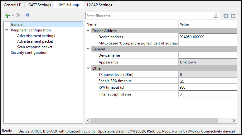
MAC-based 'Company assigned' part of address
When checked, the
'Company assigned' part of address
is generated based on the MAC address of the PC.
Device name
The device name displays on the peer side. It can be up to 248 bytes.
This parameter:
has the default-associated Read (without authentication/authorization) property
configures the GAP Service Device Name Characteristic located in the Profile Tree
can be modified only when the device is a GATT Server.
Appearance
The device logo or appearance is a SIG-defined 2-byte value.
This parameter:
has the default-associated Read (without authentication/authorization) property
configures the GAP Service Appearance Characteristic located in the Profile Tree
can ber modified only when the device is a GATT Server.
Adv/Scan TX power level (Option4)
The initial transmitter power level (dBm) of the advertisement or scan channels upon startup. Default: 0 dBm. Possible values: -20 dBm, -16 dBm, -12 dBm, -6 dBm, 0 dBm, 4 dBm.
Connection TX power level (Option4)
The initial transmitter power level (dBm) of the connection channels upon startup. Default: 0 dBm. Possible values: -20 dBm, -16 dBm, -12 dBm, -6 dBm, 0 dBm, 4 dBm.
TX power level (Option2, Option3)
The initial transmitter power level (dBm) upon startup. Default: 0 dBm. Possible values: 20dBm, -16 dBm, -12 dBm, -8 dBm, -6dBm, -4 dBm, 0 dBm, 4 dBm, 8 dBm, 12 dBm.
Note:
TheTX power level (dBm)parameter on theGAP Settings tab Generalscreen is not applicable toCYW20829devices and has no effect. Leave the default value (0dBm) in this field when using aCYW20829device.
Note:
Check your project device datasheet to know which TX power levels the device supports.
Bond list size (Option4)
The maximum number of bonded devices supported by this device. The valid range is 1 - 128. Default: 16.
Note:
The maximum number of bonded devices is also limited by the size of the available application flash (emulated EEPROM area) size to be consumed for data storage. The consumed application flash size is calculated as the multiple of the number of supported services and the multiple of the number of supported bonded devices.
RPA timeout (Option2, Option3)
The interval of random address refreshing (seconds). The valid range is 1 - 41400. Default: 900.
Filter-accept list size (Option2, Option3 )
The maximum number of devices that can be added to the Filter accept list. The valid range is 0 - 128. Default: 0.
GAP Settings tab Advertisement settings
Option4
These parameters are available when the device is configured to contain a Peripheral or Broadcaster
GAP role
.
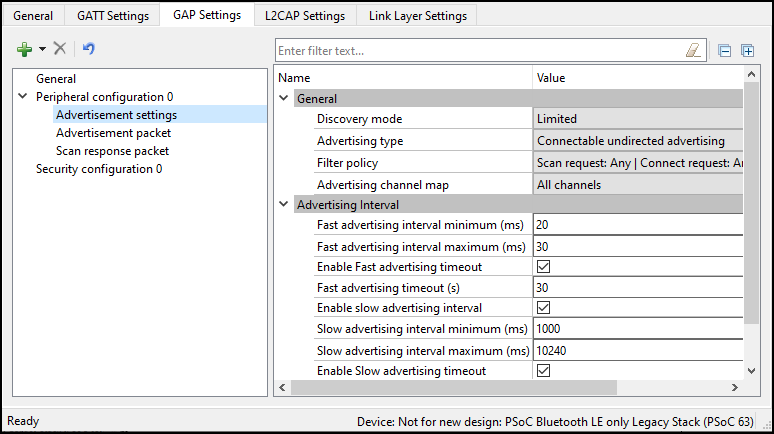
General
Discovery mode
Non-discoverable – The device cannot be discovered by a Central device.
Limited – Enables a device to be discoverable only for a limited period of time, during temporary conditions, or for a specific event. The device advertising in Limited Discoverable mode can connect to the Central device that is performing the Limited Discovery procedure. The timeout duration is defined by the applicable advertising timeout parameter.
General – The device is used by devices to be discoverable continuously or for no specific condition. The device advertising in General Discoverable mode can connect to the Central device that is performing the General Discovery procedure.
Advertising type
This parameter defines the advertising type to be used by the LL for appropriate
Discovery mode
.
Connectable undirected advertising – Advertises advertising and scan response data. It allows any other device to connect to this device.
Scannable undirected advertising – Broadcasts advertising data and scan response data to active scanners.
Non-connectable undirected advertising – Broadcasts advertising data.
Filter policy
This parameter defines the advertising type to be used by the LL for appropriate
Discovery mode
.
Scan request – Any | Connect request: Any – Processes scan and connect requests from all devices.
Scan request – Filter accept list | Connect request: Any – Processes scan requests only from the devices in the Filter accept list and connect requests from all devices.
can request – Any | Connect request: Filter accept list – Processes scan requests from all devices and connect requests only from the devices in the Filter accept list.
Scan request – Filter accept list | Connect request: Filter accept list – Processes scan and connect requests only from the devices in the Filter accept list.
Advertising channel map
This parameter is used to enable a specific advertisement channel.
Channel 37 – Enables advertisement channel #37.
Channel 38 – Enables advertisement channel #38.
Channel 39 – Enables advertisement channel #39.
Channels 37 and 38 – Enables advertisement channels #37 and #38.
Channel 37 and 39 – Enables advertisement channels #37 and #39.
Channels 38 and 39 – Enables advertisement channels #38 and #39.
All channels – Enables all three advertisement channels.
Advertising interval
This parameter defines the interval between two advertising events. Set the permissible minimum and maximum values of two
Advertising interval
types: Fast advertising interval and Slow advertising interval. Typically, after the device initialization, a peripheral device uses the Fast advertising interval. After the Fast advertising interval timeout value expires, and if a connection with a Central device is not established, then the Profile switches to Slow advertising interval to save the battery life. After the Slow advertising interval timeout value expires, CY_BLE_EVT_GAPP_ADVERTISEMENT_START_STOP event is generated.
Note:
The Advertising interval requires aligning with the selected Profile specification.
Fast advertising interval
This advertisement interval results in faster LE Connection. The Bluetooth® resource uses this interval value when the connection time is between the specified minimum and maximum values of the interval.
Minimum – The minimum interval for advertising data and establishing the LE Connection. The parameter is configured to increment in multiples of 0.625 ms. The valid range is from 20 ms to 10240 ms.
Maximum – The maximum interval for advertising data and establishing the LE Connection. The parameter is configured to increment in multiples of 0.625 ms. The valid range is from 20 ms to 10240 ms.
Timeout – The timeout value of advertising with fast advertising interval parameters. When equals 0, the device is advertising continuously and slow advertising settings become unavailable. A timeout cannot occur before the advertising interval expires. So, if a timeout value is smaller than the fast advertising interval minimum value, a warning displays.
Slow advertising interval
Defines the advertising interval for slow advertising. This is an optional parameter to implement advertising with a lower duty cycle to save battery life. The Slow advertising interval parameters are applied to the device after an internal fast advertising interval timeout occurs. The minimum and maximum values defined using this parameter allow the Bluetooth® LE Stack to expect advertising to happen within these intervals. This parameter is not applicable in General discovery mode.
Minimum – The minimum interval for advertising data and establishing the LE Connection. The parameter is configured to increment in multiples of 0.625 ms. The valid range is from 20 ms to 10240 ms.
Maximum – The maximum interval for advertising data and establishing the LE Connection. The parameter is configured to increment in multiples of 0.625 ms. The valid range is from 20 ms to 10240 ms.
Timeout – The timeout value of advertising with fast advertising interval parameters. When equals 0, the device is advertising continuously and slow advertising settings become unavailable. A timeout cannot occur before the advertising interval expires. So, if a timeout value is smaller than the fast advertising interval minimum value, a warning displays.
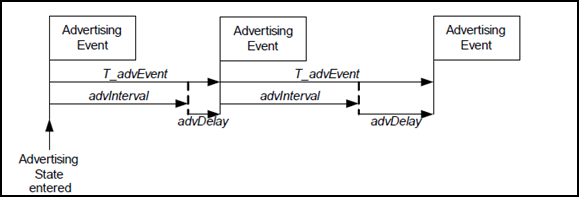
AdvDelay
– A pseudo-random delay of 0-10 ms.
Complete Advertising Event
– Consists of one advertising PDU sent into each of the used advertising channels.
Option2, Option3
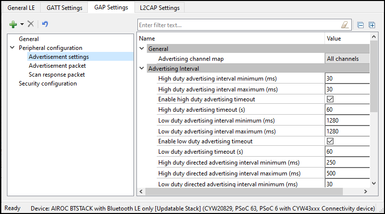
General
Advertising channel map
This parameter is used to enable a specific advertisement channel:
Channel 37 – Enables advertisement channel #37.
Channel 38 – Enables advertisement channel #38.
Channel 39 – Enables advertisement channel #39.
Channels 37 and 38 – Enables advertisement channel #37 and #38.
Channels 38 and 39 – Enables advertisement channels #38 and #39.
All channels – Enables all three advertisement channels.
Advertising interval
This parameter defines the interval between two advertising events.
High duty advertising interval
Minimum – The minimum interval for advertising data and establishing the LE Connection. The parameter is configured to increment in multiples of 0.625 ms
Maximum – The maximum interval for advertising data and establishing the LE Connection. The parameter is configured to increment in multiples of 0.625 ms.
Duration – The duration of advertising with high-duty advertising interval parameters. When not enabled, the device is advertising continuously.
Low duty advertising interval
Minimum – The minimum interval for advertising data and establishing the LE Connection. The parameter is configured to increment in multiples of 0.625 ms.
Maximum – The maximum interval for advertising data and establishing the LE Connection. The parameter is configured to increment in multiples of 0.625 ms.
Duration – The duration of advertising with high-duty advertising interval parameters. When not enabled, the device is advertising continuously.
High duty directed advertising interval
Minimum – The minimum interval for advertising data and establishing the LE Connection. The parameter is configured to increment in multiples of 0.625 ms.
Maximum – The maximum interval for advertising data and establishing the LE Connection. The parameter is configured to increment in multiples of 0.625 ms.
Low duty directed advertising interval
Minimum – The minimum interval for advertising data and establishing the LE Connection. The parameter is configured to increment in multiples of 0.625 ms.
Maximum – The maximum interval for advertising data and establishing the LE Connection. The parameter is configured to increment in multiples of 0.625 ms
Duration – The duration of advertising with high-duty advertising interval parameters. When not enabled, the device is advertising continuously.
High duty non connectable advertising interval
Minimum – The minimum interval for advertising data and establishing the LE Connection. The parameter is configured to increment in multiples of 0.625 ms.
Maximum – The maximum interval for advertising data and establishing the LE Connection. The parameter is configured to increment in multiples of 0.625 ms.
Duration – The duration of advertising with high-duty advertising interval parameters. When not enabled, the device is advertising continuously.
Low duty non connectable advertising interval
Minimum – The minimum interval for advertising data and establishing the LE Connection. The parameter is configured to increment in multiples of 0.625 ms.
Maximum – The maximum interval for advertising data and establishing the LE Connection. The parameter is configured to increment in multiples of 0.625 ms.
Duration – The duration of advertising with high-duty advertising interval parameters. When not enabled, the device is advertising continuously.
GAP Settings tab Advertisement packet
This Advertisement packet section displays when the device is configured to contain a Peripheral or Broadcaster
GAP role
. It is used to configure Advertisement data.
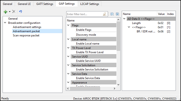
Advertisement/Scan response packet data settings
Advertisement (AD) or Scan response packet data is a 31-byte payload used to declare the device's Bluetooth® Low Energy capability and its connection parameters. This data structure is shown in the below graph per Bluetooth® specification.
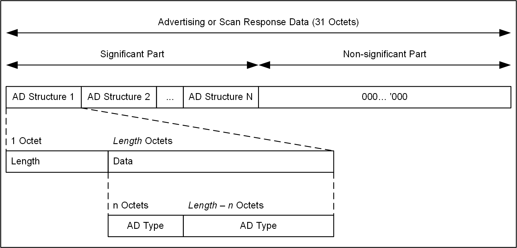
A data packet can contain a number of AD structures. Each of these structures is composed of the following parameters:
AD Length
– The size of the AD Type and AD Data in bytes.
AD Type
– The type of an advertisement within the AD structure.
AD Data
– Data associated with the AD Type.
The total length of a complete Advertising packet cannot exceed 31 bytes.
An example structure for Advertisement data or Scan response data is AD Structure Element Definition:
AD Length – Size of AD Type and associated AD Data = 5 bytes
AD Type (1 byte) – 0x03 (Service UUID)
AD Data (4 bytes) – 0x180D, 0x180A (Heart Rate Service, Device Information Service)
The following table shows the AD Types:
AD Type | Description |
|---|---|
Flags | Flags to broadcast the underlying Bluetooth® LE transport capability such as Discoverable mode, LE only, etc. |
Local Name | Device Name (complete of shortened). The device name value comes from the Device name field on the GAP Settings tab, under General . |
TX Power Level | Transmit Power Level. Taken from the Adv/Scan TX power level ( Option4 ) or TX power level ( Option2 , Option3 ) field on the GAP Settings tab, under General . |
Peripheral Connection Interval Range | The preferred connection interval range for the device. Not available in the Broadcaster GAP role. |
Service UUID | The list of device-implemented Service UUIDs to be broadcasted. There are different AD Type values to advertise 16-bit, 32-bit, and 128-bit Service UUIDs. 16-bit and 32-bit Service UUIDs are used if they are assigned by the Bluetooth® SIG. |
Service Solicitation | The list of Service UUIDs from the central device to be used by the peripheral device. There are different AD Type values to advertise 16-bit, 32-bit, and 128-bit Service UUIDs. |
Service Data | 2/4/16-byte Service UUID, followed by additional Service data. |
Security Manager TK value | A temporal key to use at the time of pairing. Not available in the Broadcaster GAP role. |
Appearance | The device external appearance. The value comes from the Appearance field on the GAP Settings tab, under General . |
Public Target Address | The public device address of intended recipients. |
Random Target Address | The random device address of intended recipients. |
Advertising Interval | For Option4 , calculated as an average of Fast advertising interval minimum and maximum values configured on the GAP Settings tab, under Advertisement settings. |
LE Bluetooth® Device Address | The device address of the local device. The value comes from the Public device address field on the GAP Settings tab, under General . |
LE Role | Supported LE roles. Not available in the Broadcaster GAP role. |
URI | URI, as defined in the IETF STD 66. |
Manufacturer Specific Data | The 2-byte company identifier followed by manufacturer-specific data. |
Indoor Positioning | Data specified in the Indoor Positioning Service Specification . Available when the Indoor Positioning Service is in the Profile. |
GAP Settings tab Scan response packet
This
Scan response packet
t section displays when the device is configured to contain a Peripheral or Broadcaster
GAP role
. It is used to configure a
Scan response data
packet to be used in response to device scanning performed by a GATT Client device.
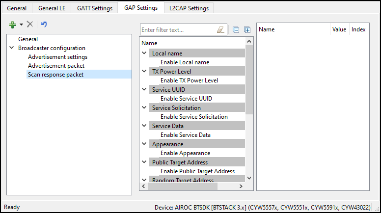
The
Scan response packet
structure is the same as of the
Advertisement packet
. See Advertisement / Scan response packet data settings under
GAP Settings tab Advertisement packet
for information on configuring the
Scan response packet
.
GAP Settings tab – Multi-advertisement
The
Multi-advertisement Settings
option is available when the device is configured to contain a Peripheral or Broadcaster
GAP role
. This feature allows you to advertise different sets of data at different time intervals. You can add up-to-ten multi-advertisement instances to the configuration tree and set different advertisement parameters and data.
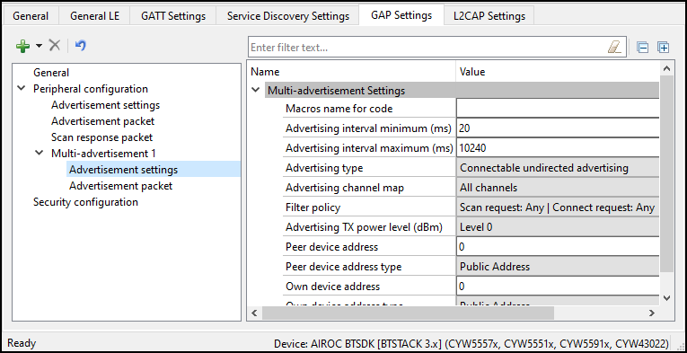
The parameters are as follows:
Macros name for code
– Provides a meaningful name to the instance to create a macro-definition in the generated code.
Advertising interval minimum (ms)/Advertising interval maximum (ms)
– Configured to increment in multiples of 0.625 ms.
Advertising type
– Has several selectable options of advertising: Connectable undirected, Connectable directed, Scannable undirected, Non-connectable undirected, Connectable low duty cycle directed.
Advertising channel map
– Selection of primary advertising channels – 37, 38, 39
Filter policy
– Setting the Scan request and Connect request filtering options
Advertising TX power level (dBm)
– Selection of a transmission power level: from -12dBm (level 0) to 4dBm (level 4
Peer device address
– The six-byte address of a peer Bluetooth® LE device
Peer device address type
– The public, random, Address or ID address of a peer Bluetooth® LE device
Own device address
– Device own six-byte address
Own device address type
– The own device public, random, Address or ID address type
For more details on the parameters, refer to
GAP Settings tab General
and
GAP Settings tab Advertisement settings
.
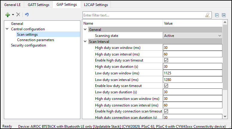
GAP Settings tab Scan settings
Option4
These parameters are available when the device is configured to contain the Central or Observer
GAP role
. Typically, during a device discovery, the GATT Client device initiates the scan procedure. It uses the Fast scan parameters for a period of time, approximately 30 to 60 seconds, and then it reduces the scan frequency using the Slow scan parameters.
Note:
The scan interval requires aligning with the user-selected Profile specification.
General
Discovery procedure
Limited – The performing device discovers a device for limited Discovery mode advertising only.
General – The performing device discovers a device for both general and limited Discovery advertising.
Scanning state
Passive – The device can only listen to advertisement packets.
Active – The device may ask the advertiser for additional information.
Scan filter policy
This parameter defines how the advertisement packets are filtered.
All
– All advertisement packets are processed
Filter accept list
only – Only advertisement packets from the devices in the Filter accept list are processed.
Duplicate filtering
When enabled, this activates filtering of duplicated advertisement data. If disabled, the Bluetooth® LE stack will not perform filtering of advertisement data.
Note:
The controller firmware has eight address locations reserved to cache the previously seen advertiser devices and filter duplicate packets from them. If there are more than eight advertising devices in the scanner proximity during the scan period, the address storing buffer is exhausted. The firmware algorithm for overwriting the address cache buffer is implemented in the FIFO fashion. When the scanner sees more than eight advertisers, the ninth advertiser replaces the first one, the tenth advertiser replaces the second one, and so on, in the address cache. After flushing the first advertiser from the address cache, if the scanner meets the first advertiser's ADV packet again, it treats it as a new device (because the first advertiser is no longer in the address cache) and sends an ADV packet to the host.
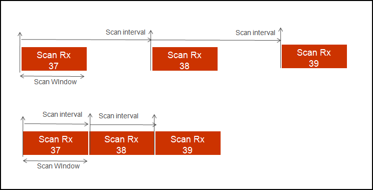
Scan parameters
These parameters define the scanning time and interval between scanning events. Two different sets of Scan parameters are used: Fast scan parameters and Slow scan parameters. Typically, after the device initialization, a central device uses the Fast scan parameters. After the Fast scan timeout value expires, and if a connection with a Peripheral device is not set, then the Profile switches to the Slow scan parameters to save the battery life. After the Slow scan timeout value expires, the CY_BLE_EVT_GAPC_SCAN_START_STOP event is generated. See the API documentation.
Fast scan parameters
– This connection type results in a faster connection between the GATT Client and Server devices than it is possible using normal connection.
Scan Window – This parameter defines the scan window when operating in Fast connection. The parameter is configured to increment in multiples of 0.625 ms. The valid range is from 2.5 ms to 10240 ms. Scan Window must be less than the Scan Interval. Default: 30 ms.
Scan Interval – This parameter defines the scan interval when operating in Fast connection. The parameter is configured to increment in multiples of 0.625 ms. The valid range is from 2.5 ms to 10240 ms. Default: 30 ms.
Scan Timeout – The timeout value of scanning with fast scan parameters. Default: 30 s. When not enabled, the device is scanning continuously. A timeout cannot occur before the scanning interval is expired, that is why if a timeout value is smaller than the slow scanning interval minimum value, a warning displays.
Slow scan parameters
– This connection results in a slower than possible connection between the GATT Client and GATT Server devices that use a normal connection. However, this method consumes less power.
Scan Window – This parameter defines the scan window when operating in Slow Connection. The parameter is configured to increment in multiples of 0.625ms. The valid range is from 2.5 ms to 10240 ms. Scan Window must be less than the Scan Interval. Default: 1125 ms.
Scan Interval – This parameter defines the scan interval when operating in Slow Connection. The parameter is configured to increment in multiples of 0.625 ms. The valid range is from 2.5 ms to 10240 ms. Default: 1280 ms..
Scan Timeout – The timeout value of scanning with slow scan parameters. Default: 150 s. When not enabled, the device is scanning continuously. A timeout cannot occur before the scanning interval expires, so if a timeout value is smaller than the slow scanning interval minimum value, a warning displays.
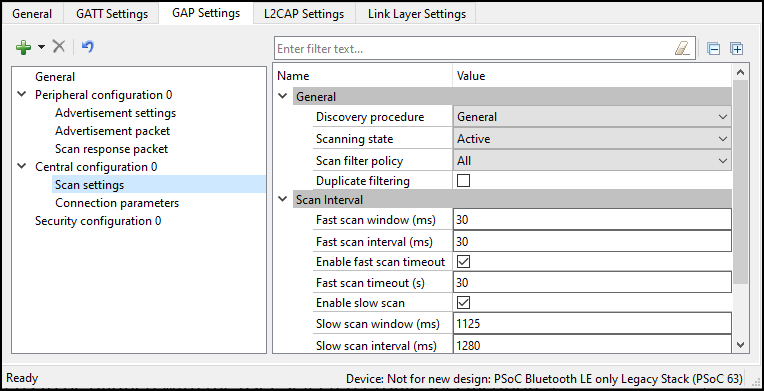
Option2
General
Scanning state
Passive – A device can only listen to advertisement packets
Active – A device may ask the advertiser for additional information
Scan interval
High duty scan parameters
Scan Window – The parameter is configured to increment in multiples of 0.625 ms. Scan Window must be less than Scan Interval.
Scan Interval – The parameter is configured to increment in multiples of 0.625 ms.
Scan Duration – The timeout value of scanning with high-duty scan parameters. Default: 30 s. When not enabled, the device is scanning continuously
Low duty scan parameters
Scan Window – The parameter is configured to increment in multiples of 0.625 ms. The valid range is from 2.5 ms to 10240 ms. Scan Window must be less than Scan Interval.
Scan Interval – The parameter is configured to increment in multiples of 0.625 ms.
Scan Duration –– The timeout value of scanning with low-duty scan parameters. Default: 30 s. When not enabled, the device is scanning continuously.
High duty connection scan parameters
Scan Window – The parameter is configured to increment in multiples of 0.625 ms. Scan Window must be less than Scan Interval.
Scan Interval – The parameter is configured to increment in multiples of 0.625 ms.
Scan Duration – The timeout value of scanning with high duty connection scan parameters. Default: 30 s. When not enabled, the device is scanning continuously.
Low duty connection scan parameters
Scan Window – The parameter is configured to increment in multiples of 0.625 ms. Scan Window must be less than Scan Interval
Scan Interval – The parameter is configured to increment in multiples of 0.625 ms.
Scan Duration – The timeout value of scanning with low-duty connection scan parameters. Default: 30 s. When not enabled, the device is scanning continuously.
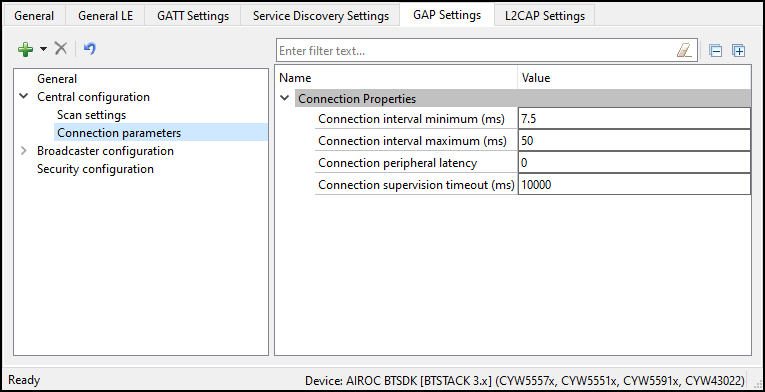
GAP Settings tab Connection parameters
These parameters define the preferred Bluetooth® LE interface connection settings of the Central.
Note:
The scaled values of these parameters are used internally by the Bluetooth® LE stack. These are the actual values sent over the air.
Connection interval
– The Central device connecting to a Peripheral device needs to define the time interval for a connection to happen.
Minimum (ms) – This parameter is the minimum permissible connection time value to be used during a connection event. It is configured in steps of 1.25 ms. The valid range is from 7.5 ms to 4000 ms.
Maximum (ms) – This parameter is the maximum permissible connection time value to be used during a connection event. It is configured in steps of 1.25 ms. The valid range is from 7.5 ms to 4000 ms.
Note:
For the multi-connection use case, recommended the minimum connection interval per connection greater than N * Max Time taken by individual connections to complete a Bluetooth® Connection Event (CE).
Min_CI = N * Average Time Per CE
The average time for each CE is the amount of time taken to complete one Bluetooth® LE TX and RX transaction. This time varies depending on the Link Layer Data Length Extension (DLE) and Bluetooth® LE data rate (1 Mbps or 2 Mbps) configuration. The application can use the following timing lookup table for the CE value:
If DLE is enabled and data rate is 1Mbps, Average time = 6ms
If DLE is enabled and data rate is 2Mbps, Average time = 3.5ms
If DLE is disabled and data rate is 1Mbps, Average time = 2ms
If DLE is disabled and data rate is 2Mbps, Average time = 1.6ms
For example, if an application supports 4 Bluetooth® LE connections with DLE and 1-Mbps data rate, the recommended minimum connection interval for each of the connections is:
4 * 6 = 24 ms
Note:
Connection intervals shorter than this value will still work, but under certain conditions, real-time control procedures (connection update, channel map update etc.) with a shorter update instance might result in a link disconnection.
Peripheral Latency
– Defines the latency of the peripheral by responding to a connection event in consecutive connection events. This is expressed in terms of multiples of connection intervals, where only one connection event is allowed per interval. The valid range is 0 - 499 events.
Connection Supervision Timeout
– This parameter defines the LE link supervision timeout interval. It defines the timeout duration for which an LE link needs to be sustained if there is no response from the peer device over the LE link. The time interval is configured in multiples of 10 ms. The valid range is from 100 ms to 32000 ms.
Note:
For proper operation, the Connection Supervision Timeout must be larger than (1 + Peripheral latency) * Connection Interval * 2 (ms). Refer to Bluetooth® Core Specification Volume 6, Part B, Chapter 4.5.2 for more information on Connection Supervision Timeout.
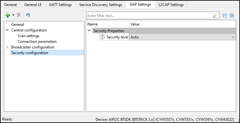
GAP Settings tab Security configuration
This Security configuration section contains several parameters to configure the global security options.
Option2
,
Option3
, and
Option4
devices have different sets of parameters.
These parameters are configurable only if a connectable GAP role, Peripheral or Central, is selected. You can optionally set each parameter using its own unique
Security Properties
in the
Profile Tree
.
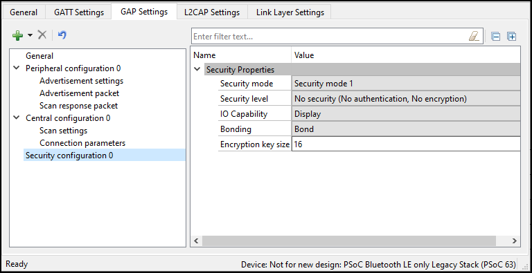
Security Properties
Security mode
Defines the GAP security modes. Both available modes may support authentication:
Mode 1 – For designs where data encryption is required.
Mode 2 – For designs where data signing is required.
Security level
Option4
library: Enables different levels of security depending on the selected Security mode.
Mode 1
No security – The device does not use encryption or authentication.
Unauthenticated pairing with encryption – The device sends encrypted data after establishing a connection with the remote device.
Authenticated pairing with encryption – The device sends encrypted data after establishing a connection with the remote device. To establish a connection, the devices perform the authenticated paring procedure.
Authenticated LE Secure Connections pairing with encryption – The device uses an algorithm called Elliptic curve Diffie–Hellman (ECDH) for key generation, and a new pairing procedure for the key exchange. It also provides a new protection method from Man-In-The-Middle (MITM) attacks
- Numeric Comparison.
Mode 2
Unauthenticated pairing with data signing – The device performs data signing prior to sending it to the remote device after a connection is set up.
Authenticated pairing with data signing – The device performs data signing prior to sending it to the remote device after a connection is set up. To establish a connection, the device performs the authenticated paring procedure.
Option2, Option3:
Provides the following levels of security:
Auto – The recommended choice for most applications to connect to the widest range of devices. Allows the stack to choose the highest level of security possible between the two devices.
Secure Connections – Can be set by applications that need to enforce secure connections.
Authentication – Can be set by applications that need to enforce Authentication.
Secure Connections with MITM protection – Can be set by applications that need to enforce secure connections with man-in-the-middle (MITM) protection.
Note:
This parameter is used in BTSTACK 3.0 or above.
Keypress notifications
Provides an option for a keyboard device during the LE secure pairing process to send key press notifications when the user enters or deletes a key. This option is available when the Security level is set to Authenticated LE Secure Connections pairing with encryption and I/O capabilities option is set to either Keyboard or Keyboard and Display.
I/O capabilities
Refers to the device input and output capability, which can enable or restrict a particular pairing method or security level.
Display – In devices with the display capability and may display authentication data. GAP authentication is required.
Display Yes/No – In devices with a display and at least two input keys for the Yes/No action. GAP authentication is required.
Keyboard – In devices with a numeric keypad. GAP authentication is required.
No Input/No Output – In devices without any capability to enter or display the authentication key data to the user. Used in mouse-like devices. No GAP authentication is required.
Keyboard and Display – In devices like PCs and tablets. GAP authentication is required.
Bonding Requirement
Used to configure the bonding requirements. The purpose of bonding is to create a relation between two Bluetooth® devices based on a common link key (a bond). The link key is created and exchanged (pairing) during the bonding procedure and is expected to be stored by both Bluetooth® devices, to be used for future authentication. The maximum number of remote devices that can be bonded is 128.
Bonding – The device stores the link key of a connection after paring with the remote device in the application flash memory. If a connection is lost and re-established, the device uses the previously stored key for the connection.
Note:
Bonding information is stored in RAM and is written to the application flash to be retained during a shutdown.
No Bonding – The pairing process is performed on each connection establishment.
Encryption Key Size
Defines the encryption key size based on the Profile requirement. The valid values of an encryption key size are 7 - 16 bytes.