AN217666 PSoC™ 6 MCU interrupts
About this document
Scope and purpose
This application note explains the interrupt architecture in PSoC™ 6 MCU and its configuration using PSoC™ Creator, ModusToolbox™, and the PSoC™ 6 Peripheral Driver Library (PDL) APIs. This document serves as a guide in developing projects that use interrupts. Advanced interrupt concepts such as interrupt latency, code optimization, and debug techniques are also explained.
To access an ever-growing list of hundreds of PSoC™ code examples, please visit our code examples web page. You can also explore the Infineon video training library here.
Introduction
An interrupt is a hardware signal or an event that transfers the execution of a program from the normal flow to an alternate set of instructions. An interrupt frees the CPU from continuously polling for a specific event, and only notifies and engages the CPU when the event occurs. The alternate program flow is referred to as an interrupt service routine or ISR. An ISR is also called an interrupt handler. After the interrupt is serviced, the program flow is reverted back to the flow that was interrupted. In system-on-chip (SoC) architectures such as PSoC™, interrupts are frequently used to communicate the status of on-chip peripherals to the CPU.
While interrupts refer to those events generated by peripherals external to the CPU such as timers, serial communication blocks, and port pin signals, an exception is an event generated by the CPU such as memory access faults and internal system timer events. PSoC™ 6 MCU supports interrupts and exceptions on both its Arm® Cortex®-M4 (CM4) and Cortex®-M0+ (CM0+) CPUs.
How to use this document
This document assumes that you are familiar with the PSoC™ 6 MCU architecture, and application development for PSoC™ devices using the Infineon PSoC™ Creator integrated design environment (IDE) and Peripheral Driver Library (PDL). For an introduction to PSoC™ 6 MCU, see AN210781 - Getting Started with PSoC™ 6 MCU with Bluetooth® Low Energy (BLE) Connectivity. If you are new to PSoC™ Creator, ModusToolbox™, or PDL, see the References section for links to some of the available resources.
The Debugging tips section provides a few tips on finding and resolving common issues encountered while using interrupts. More complex topics are covered in Advanced interrupt topics.
PSoC 6 MCU interrupt architecture
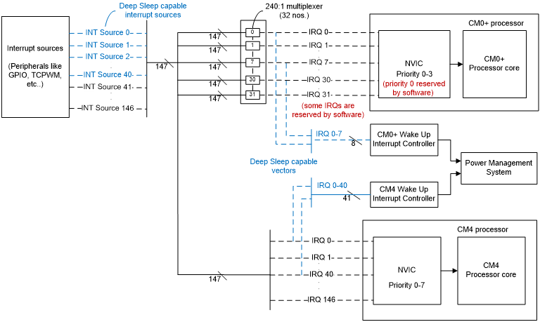
PSoC™ 6 MCU contains two CPUs: CM4 and CM0+. Interrupt signals to each CPU are handled by the respective Nested Vectored Interrupt Controller (NVIC). The NVIC enables/disables any interrupt based on the user configuration. It also resolves the interrupt priority when multiple requests occur at the same time and supports nested interrupts to allow a higher-priority interrupt to be serviced before a lower-priority ISR.
PSoC™ 6 MCU also supports a wakeup interrupt controller (WIC) and multiple synchronization blocks. The WIC block allows the CPU to wake up from sleep or deep sleep low-power modes using interrupts. The WIC block remains active while the NVIC, processor core, and other device peripherals shut down. When an interrupt triggers, the WIC activates the power management system, which restores the NVIC and the processor core along with other peripherals. Each CPU has independent WIC settings.
Natively, CM4 supports up to 240 interrupts, while CM0+ supports 32 interrupts. The number of CPU interrupts available to the user varies depending on the device, see Table 1.
CM4 supports configurable interrupt priority from 0 to 7. CM0+ supports priority from 0 to 3.
There are up to 175 interrupt sources (also referred to as system interrupts) in a PSoC™ 6 MCU device. System interrupts can trigger either or both CPUs.
The WIC block can wake up a CPU from deep sleep power mode. Table 2 lists the interrupt sources that can wake a CPU from deep sleep.
One or more system interrupts can be selected as the source for the CPU non-maskable interrupt (NMI), see Table 1.
| Parameter | CY8C61x6/7, CY8C62x6/7, CY8C63xx | CY8C62x8/A | CY8C62x5 | CY8C62x4 |
|---|---|---|---|---|
Number of system interrupts (“N”) | 147 | 168 | 174 | 175 |
Number of deep sleep-capable system interrupt sources (“W”) | 41 | 39 | 39 | 45 |
Number of CM0+ interrupt vectors available | 32 (8 deep sleep-capable) | 8 hardware (deep sleep-capable) 8 software triggered | 8 hardware (Deep sleep-capable) 8 software triggered | 8 hardware (Deep sleep-capable) 8 software triggered |
Number of system interrupts that can be connected to a CM0+ multiplexer/vector | 1 | All (168) | All (174) | All (175) |
Number of CM4 interrupt vectors available | 240 | 240 | 240 | 240 |
Number of system interrupts that can be connected to a CM4 multiplexer/vector | 1 (1:1 mapping) | 1 (1:1 mapping) | 1 (1:1 mapping) | 1 (1:1 mapping) |
Number of system interrupts that can be connected to CM0+/CM4 NMI interrupt | 1 | 4 | 4 | 4 |
CY8C61x6/7, CY8C62x6/7, and CY8C63xx interrupt architecture

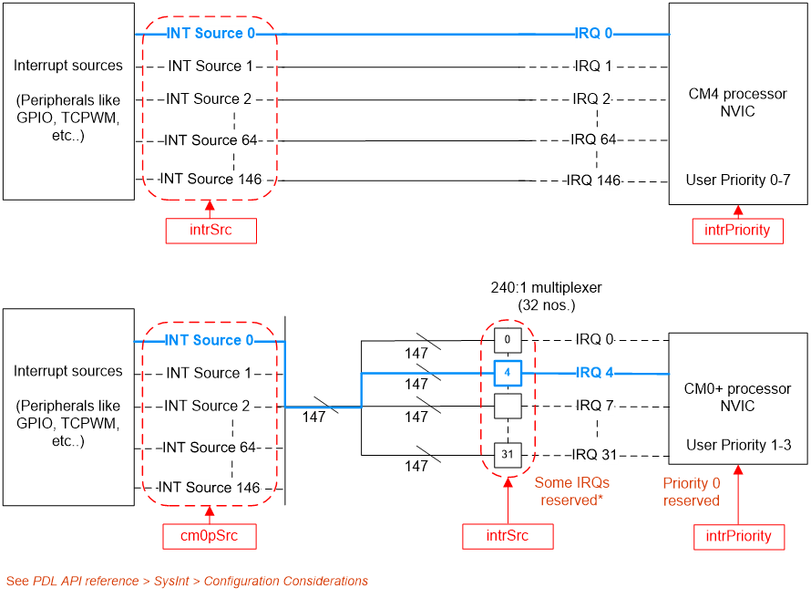
CY8C61x6/7, CY8C62x6/7, and CY8C63xx devices support up to 147 system and peripherals interrupt sources.
For CM4, the 147 interrupt sources are directly mapped to its first 147 IRQ lines, i.e., INT source n is connected to IRQ n, where ‘n’ = 0 to 146. For CM0+, a 240:1 multiplexer is present in front of each of 32 IRQs and redirects any of the 147 interrupts to one of CM0+ IRQ lines. This enables any interrupt source to trigger any CM0+ IRQ.
CY8C62x4, CY8C62x5, and CY8C62x8/A interrupt architecture
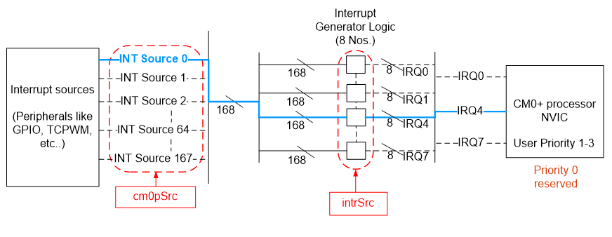
In CY8C62x4, CY8C62x5, and CY8C62x8/A devices, the ‘N’ interrupt sources are directly mapped to the first ‘N’ IRQ lines of the CM4. The CM0+ supports 16 interrupts, of which the first 8 interrupts (IRQ 0 – 7) can be triggered by a peripheral interrupt source; the other 8 are software-triggered interrupts. One or more system interrupts (upto ‘N’) can be assigned as the interrupt source for each of the IRQ 0 - 7 lines. This allows multiple interrupt sources to be connected to the same CPU interrupt simultaneously.
The WIC block supports up to ‘W’ interrupts that can wake up a CPU from deep sleep power mode; see “Number of deep sleep-capable system interrupt sources” in Table 1.
Table 2 lists the interrupt sources that can wake a CPU from deep sleep.
Types of interrupts
There are two kinds of interrupt sources in PSoC™ 6 MCU:
Fixed-function interrupt sources
These are predefined interrupt sources from on-chip peripherals such as GPIO, TCPWM, SCB, and BLE Radio. Interrupts from fixed-function sources are generated from configurable events; for example, an interrupt on a rising for example signal on an input pin (GPIO), or an interrupt on a counter overflow (TCPWM).
Universal Digital Block (UDB) interrupt sources
UDBs consist of programmable logic devices (PLDs), datapaths, and flexible routing, which can be used to synthesize different digital functions such as Timer, PWM, UART, SPI and many more. In contrast to fixed-function interrupt sources, any digital signal generated in a UDB can trigger an interrupt. The signals are routed to the interrupt controller through the routing fabric known as Digital System Interconnect (DSI). UDB sources are available only in CY8C61x6/7, CY8C62x6/7, and CY8C63xx devices
For a complete list of interrupt sources in PSoC™ 6 MCU, see Appendix A.
Level and pulse interrupts
Both CM0+ and CM4 NVICs support level and pulse signals on IRQ lines. The classification of an interrupt as level or pulse is based on the interrupt source. A fixed-function interrupt is treated as level-sensitive. For the DSI sources, which include the UDB, the interrupt can be configured as either rising-edge-triggered or level-triggered. This configuration is available only in PSoC™ Creator. For more details on selecting the interrupt type, refer to the PSoC™ Creator Component datasheet or PDL API reference for the interrupt source.
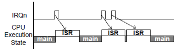
For level interrupts, if the interrupt signal is still HIGH after completing the ISR, the interrupt is still pending and the ISR is executed again. Figure 3 illustrates the timing diagram for level-triggered interrupts, where the ISR is executed if the interrupt signal is HIGH.
For pulse interrupts, while the ISR is being executed by the CPU, one or more rising edges of the interrupt signal are logged as a single pending request. The pending interrupt is serviced again after the current ISR execution is complete. Figure 4 illustrates the timing diagram for pulse interrupts.

Interrupts and Power modes
PSoC™ 6 MCU has the following system Power modes: Low-Power (LP), Ultra-Low-Power (ULP), deep sleep, and hibernate. The Arm® CPU Power modes are active, sleep, and deep sleep; these are available in system LP and ULP Power modes.
In CPU active modes, CPUs execute code; all memory blocks and peripherals are available.
In all other Power modes (sleep, deep sleep, hibernate), CPU clocks are turned off and code execution is halted.
All peripherals available in active modes are also available in the sleep, deep sleep, and hibernate modes. Any peripheral interrupt, masked to the CPU, wakes up the CPU to Active mode.
Only a subset of peripherals operate in deep sleep mode. Interrupts from these peripherals cause a CPU to wake up to active mode. Table 2 lists these peripherals. Each CPU has a Wakeup Interrupt Controller (WIC) to wake up the CPU from its deep sleep mode. deep sleep wakeup functionality is supported only on the first 8 IRQs (0 to 7) on CM0+ and first ‘W’ IRQs on CM4, see Table 1.
During hibernate mode, all peripherals and clocks are turned off and only certain sources like Low Power Comparator, RTC, a dedicated WAKEUP pin, or an XRES event can wake up the device. The wakeup action is a device reset instead of an interrupt to the CPU.
For more details on device Power modes CPU sleep and wakeup behavior due to interrupts, see AN219528 – PSoC™ 6 MCU Low-Power Modes and Power Reduction Techniques or PSoC™ 6 MCU Architecture TRM.
| Interrupt Source | Interrupt Source Number | |||
|---|---|---|---|---|
| CY8C63xx | CY8C62x6/7CY8C61x6/7 | CY8C62x8/ACY8C62x5 | CY8C62x4 | |
GPIO Port Interrupt | 0–14 | 0–14 | 0–14 | 0–14 |
GPIO All Ports | 15 | 15 | 15 | 15 |
GPIO Supply Detect Interrupt | 16 | 16 | 16 | 16 |
Low Power Comparator Interrupt | 17 | 17 | 17 | 17 |
Serial Communication Block Interrupt | 18 | 18 | 18 | 18 |
Multi Counter Watchdog Timer | 19, 20 | 19, 20 | 19, 20 | 19, 20 |
Backup Domain Interrupt | 21 | 21 | 21 | 21 |
Other combined Interrupts for SRSS | 22 | 22 | 22 | 22 |
Combined Continuous Time Block (CTBm) Interrupt | 23 | 23 | – | – |
Bluetooth® Radio Interrupt | 24 | – | – | – |
Inter Process Communication Interrupt | 25–40 | 25–40 | 23-38 | 23-38 |
SAR ADC Interrupt | – | – | – | 39, 40 |
Individual Continuous Time Block (CTBm) Interrupt | – | – | – | 41 |
PASS Timer interrupt | – | – | – | 42 |
PASS FIFO Interrupt | – | – | – | 43, 44 |
CPU sleep and wakeup
There are two instructions that can cause the CPU to enter its sleep modes: the “Wait-for-Interrupt” [__WFI()] and “Wait-for-Event” [__WFE()]. When a WFI instruction is executed, the CPU enters sleep or deep sleep (depending on the SLEEPDEEP bit of the SCR register) and wakes up on an interrupt request (with a higher priority than the current priority level) or on debug requests. The WFE instruction is like WFI but wakes up on the next interrupt or on events like Send Event (SEV instruction), external event, or debug signals. See AN219528 for more details on sleep and wakeup instructions.
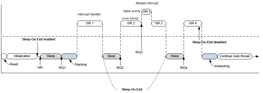
Normally, when an ISR is done executing, CPU execution returns to where it was before the ISR. PSoC™ 6 MCU supports the “Sleep-on-Exit” feature where the CPU enters or returns to sleep or deep sleep (a state similar to WFI) as soon as it completes ISR execution. As seen in Figure 5, when this feature is enabled, only one WFI instruction is needed to enter a sleep mode; the CPU returns to sleep after each ISR instead of the execution returning to main. The Sleep-on-Exit feature reduces the active cycles of the CPU and reduces the energy consumed by the stacking (PUSH to stack) and unstacking (POP from stack) of processes between interrupts. Nested interrupts are also supported when Sleep-on-Exit is enabled.
The Sleep-on-Exit feature is enabled by setting SLEEPONEXIT bit of the SCR
register. There is also a PDL function available – Cy_SysPm_SleepOnExit; see
Configuring interrupts using PDL for details.
Interrupt configuration
This section lists the steps needed to set up interrupts on a PSoC™ 6 MCU device, without going into details of the software used to do them. These steps are common to both CM0+ and CM4 unless specified otherwise, and must be done for each CPU separately.
- Out of device reset, all interrupts are disabled, and interrupt priorities are set to zero
- Configure the priority level of the required IRQ in the NVIC
- Configure the interrupt path
- Choose which interrupt source is connected to the desired IRQ of the CPU. For CM0+, select the appropriate peripheral interrupt to be connected to the CPU. For CM4, this is not configurable. Interrupt source n is always connected to IRQn
- Configure the interrupt source (peripheral) and enable its interrupt
- Configure the vector table with the address of the ISR (vector). The vector table stores the entry addresses for each exception handler; see Exception Vector Table in Interrupts chapter of PSoC™ 6 MCU Architecture TRM.
- Optional: Clear pending interrupt states in the NVIC
- If enabling a previously disabled interrupt, it is a good practice to clear the pending state of the NVIC before enabling the interrupt. This prevents any false trigger caused by previous interrupts that created a pending state
- Enable the interrupt in the NVIC
- Enable global interrupts. Interrupt configuration is complete
An enabled interrupt is triggered when the hardware signal from the interrupt source is active and there is no higher priority interrupt that is executing. When this happens, CPU execution jumps to the location in its vector table that corresponds to the triggered interrupt. This location contains the address of the ISR associated with that interrupt.
The ISR executes the tasks required to handle the interrupt. Typically, the first thing an ISR does is clearing the interrupt source to avoid re-entering the ISR. When the ISR terminates, the CPU returns to the address it was executing before it was interrupted. The following sections describe the software tools available for performing the steps described.
Configuring interrupts using ModusToolbox
ModusToolbox™ applications support both the PSoC™ 6 Hardware Abstraction Layer (HAL) and Peripheral Driver Library (PDL) libraries.
Using HAL
The HAL gives an abstracted interface to configure and use various blocks on Infineon MCUs. There is no separate block for interrupts in HAL. The interrupts for different blocks are configured using the HAL APIs specific to those blocks.
For example, in the case of a GPIO Interrupt, interrupts arising from the GPIO block are configured using the GPIO HAL APIs. The steps to configure the GPIO HAL block for this example include:
- Initializing the GPIO pin: The GPIO pin, direction, drive mode, and
initial value are passed to the
cyhal_gpio_initHAL API function - Registering the interrupt callback function: The callback function for
the interrupt is registered with the GPIO pin using
cyhal_gpio_register_callback - Configuring the interrupt: The interrupt settings such as the GPIO event
and interrupt priority are configured using
cyhal_gpio_enable_event - See the Interrupts on GPIO events code snippet in GPIO HAL API Reference Guide
For more details on HAL APIs, see PSoC™ 6 HAL on GitHub.
Using Device Configurator and PDL
Interrupts can be configured in ModusToolbox™ using the Device Configurator, the GUI-based tool used to enable and configure MCU peripherals and their interrupt parameters.
Figure 6 shows the configuration of a GPIO pin to generate interrupt on a falling edge.
Figure 6.
ModusToolbox™ peripheral configuration
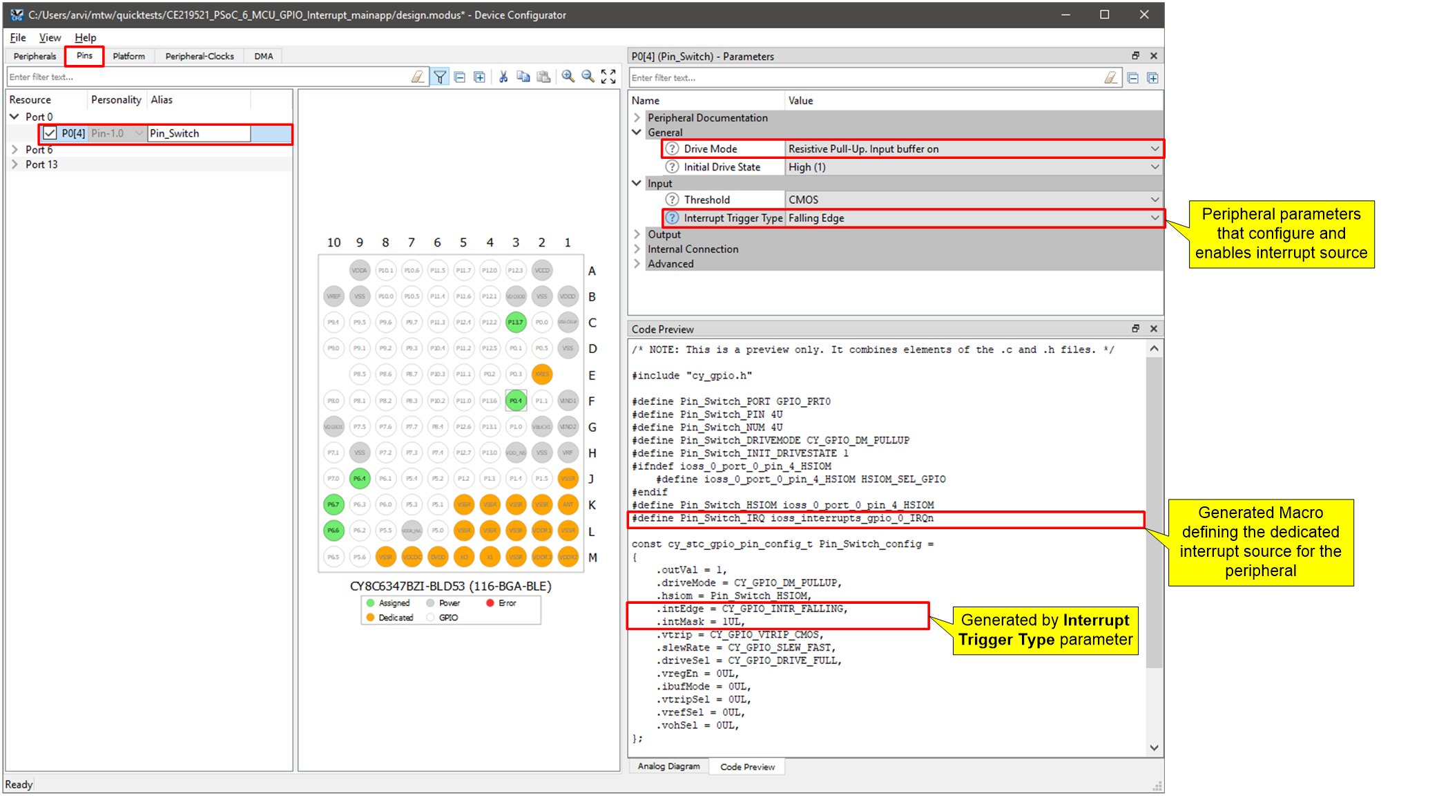
Based on the configuration, ModusToolbox™ generates the ‘C’ code to achieve the desired configuration. The code generated can be viewed in the Code Preview pane; it is added to relevant cycfg_xxx.c/h files in the TARGET_<BSP name>/COMPONENT_BSP_DESIGN_MODUS/GeneratedSource folder in the ModusToolbox™ application. The generated code includes macros defining the interrupt source numbers and any peripheral configuration that is necessary to set up and enable the interrupt source. This simplifies the process of searching for the dedicated interrupt numbers in the device header file. The user application only needs to enable the interrupt vector on the CPU and assign an interrupt handler function as described in Configuring interrupts using PDL.
Configuring interrupts using PDL
The Peripheral Driver Library (PDL) simplifies software development for the PSoC™ 6 MCU architecture. The PDL reduces the need to understand register usage and bit structures, so easing software development for the extensive set of peripherals available.
PDL API function calls are used to configure, initialize, enable, and use a peripheral driver. One such driver is System Interrupts (SysInt). SysInt provides structures and functions to configure and enable interrupt functionality. PDL also supports the CMSIS-Core libraries which include NVIC functions used for interrupt configuration.
The following steps use PDL and NVIC APIs to set up an interrupt to trigger on a signal from a peripheral.
- Configure the peripheral to generate the interrupt. For example, for a GPIO, configure the drive mode (pull up or pull down), interrupt signal generation on falling or rising edge, and unmask the interrupt. Refer to the PDL API reference documentation for your peripheral for this information
- Configure the interrupt using the structure provided by the SysInt API.
The structure is defined in the PDL
SysInt driver
file cy_sysint.h:
Initialization configuration structure
fora single interrupt channel
/
typedefstruct(
IRQn_Type intrSrc
;
/**< Interrupt source */
if (CY_CPU_CORTEX_M0P)
cy_en_intr_t cm0pSrc
;
/**< (CM0+ only) Maps cm0pSrc device interrupts to intrSrc */
endif
uint32_t intrPriority
;
/**< Interrupt priority number (Refer to __NVIC_PRIO_BITS) */
)
cy_stc_sysint_t
;
This structure is used to configure the following (see Figure 7 for a quick summary) :
Interrupt Source (
intrSrc)- These are the dedicated interrupt numbers as defined in the device header file (example: cy8c6247bzi_d44.h)
This selection depends on which CPU you want to assign the interrupt to
- For CM4, this number represents both the interrupt number of the source as well as the CPU IRQ number. Select the interrupt number of the peripheral interrupt you wish to route to the CPU. For example, to route Port 0 GPIO interrupt, assign a value of ioss_interrupts_gpio_0_IRQn (=0).
- For CM0+, this number represents one of the 32 multiplexers available for routing an interrupt to CM0+. Because each multiplexer is connected to a dedicated CM0+ IRQ line, use this to select the target CM0+ IRQ number. For example, to use multiplexer #4 (CM0+ IRQ#4), use “NvicMux4_IRQn” (=4).
CM0+ interrupt number (
cm0pSrc)- This parameter is applicable only for CM0+.
- This represents the interrupt number of the source, which is to be routed to the multiplexer/CM0+ interrupt generator logic, selected using the intrSrc parameter. Select the interrupt number of the peripheral interrupt you wish to route to the CPU; for example, to route Port 0 GPIO interrupt, assign a value of “ioss_interrupts_gpio_0_IRQn” (=0).
Interrupt priority (intrPriority)
- Set the priority of the interrupt. For CM4, supported priorities are 0 to 7. For CM0+, supported priorities are 0 to 3
Note:
- On CM0+, some IRQs are reserved for use by software and not available to the user. See “Configuration Considerations” under SysInt driver in PDL API reference documentation for the list of reserved IRQs
- On CM0+, the interrupt priority 0 is reserved for system calls
Figure 7.
SysInt PDL structure parameters (highlighted in red) used for interrupt configuration (sample configured path highlighted in blue)
For CY8C62x4, CY8C62x5 and CY8C62x8/A devices:
- Call
Cy_SysInt_Init(&SysInt_SW_cfg_1, ISR_1_handler) - Here,
SysInt_SW_cfg_1is the name of the configured structure.ISR_1_handleris the name of the interrupt handler that executes when the interrupt triggers. This function applies the routing and priority configuration of the interrupt but does not enable it - Call
NVIC_ClearPendingIRQ(SysInt_SW_cfg_1.intrSrc)to clear any pending interrupts - Call
NVIC_EnableIRQ(SysInt_SW_cfg_1.intrSrc)to enable the interrupt - Call the
_enable_irq()function to enable global interrupts. This is safe to perform as the first step, as individual CPU interrupts have not been enabled yet. You can also perform this later but interrupts are disabled at startup unless this is called
In addition to the PDL SysInt driver, the system power modes (SysPm) driver API enables the Sleep-on-Exit feature. If sleep or deep sleep mode is used in the application along with interrupts, this feature enables the firmware to keep the system in a that sleep mode almost all the time, only wake up to execute the interrupt and then immediately go back to the same sleep mode. The program does not return to the main function and stays either in the interrupt handler or in the same sleep state unless the Sleep-on-Exit feature is disabled again.
Cy_SysPm_SleepOnExit(true);Configuring interrupts using PSoC Creator
PSoC™ Creator provides a graphical interface for routing signals from
peripherals to a CPU IRQ line. PSoC™ Creator provides an Interrupt
(SysInt) Component. This component is a UI element on top of the
SysInt PDL driver discussed in the previous section. Based on the
configuration in the Component, PSoC™ Creator generates code to initialize peripherals,
route interrupts, and populate the interrupt configuration structure. This reduces the
amount of code you must write when setting up interrupts.
The following section shows steps to use PSoC™ Creator to configure an interrupt. See the References section for code examples.
Using the schematic (TopDesign)
Drag and drop a Component from the Component Catalog onto the TopDesign. Use TopDesign to place and configure peripherals that provide a source of interrupt. Consult the Component datasheet for information on the peripheral’s interrupt configuration. Some peripherals provide an interrupt terminal (e.g., TCPWM). Place an instance of the SysInt Component and connect it to the interrupt terminal of the peripheral.
Figure 8.
TopDesign with interrupt componentSysInt (Interrupt) configuration

Some peripherals do not have an external interrupt terminal (e.g., SCB has interrupts built-in) or may have an option to expose it (e.g., UART).
The Interrupt Component has two configurable options as seen in Figure 9.
Figure 9.
SysInt (Interrupt) configuration
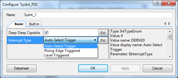
Deep sleep capable
Enable this checkbox if you want the interrupt to be assigned to a CPU IRQ line that is deep sleep-capable. You must ensure that the interrupt source is also active and capable of providing the interrupt signal during deep sleep, failing which PSoC™ Creator throws an error when the project is built. Note that this option is significant only in case the interrupt is assigned to CM0+ which has 8 (IRQ 0-7) deep sleep slots to route to. The checkbox is provided only for guidance in automatically assigning an IRQ for the interrupt and can be overridden by manual assignment from the CyDWR window. For CM4, if the interrupt source is deep sleep-capable (IRQ 0-40), disabling the checkbox has no effect on the deep sleep functionality of the interrupt.
Interrupt type
There are three options available for Interrupt type in the Interrupt Component configuration: Auto-Select Trigger, Rising-Edge Triggered, and Level Triggered. The selection of a particular option depends on the interrupt source (fixed-function or UDB/DSI) and the application requirements. In most cases, leave the option to Auto-Select to let PSoC™ Creator derive the interrupt type from the nature of the interrupt source.
Choose only level-triggered for Fixed-function interrupt sources. Choose Level-triggered or Rising-Edge for UDB sources.
Using the design-wide resource window (CyDWR)
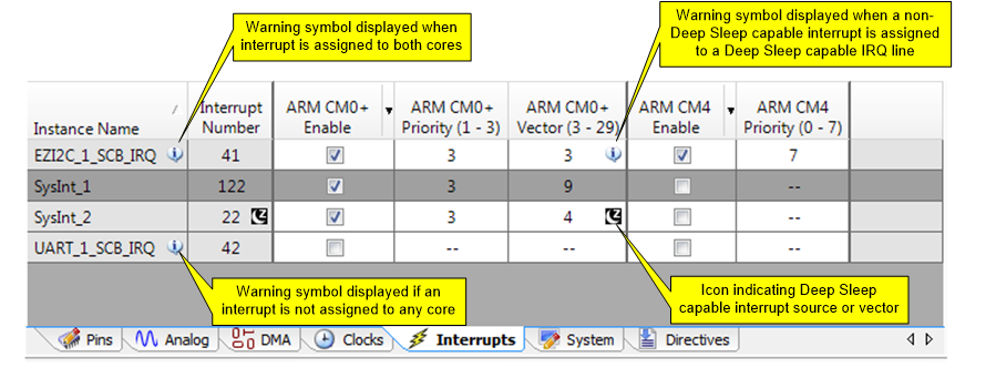
The design-wide resources window (.cydwr file) of the PSoC™ Creator project has an Interrupts tab. This tab lists the instance names of all interrupts used in the TopDesign schematic along with their interrupt numbers.
Each interrupt can be allocated to either CM0+ or CM4 or both the CPUs using the ‘ARM CMx Enable’ checkbox. Unless specified otherwise, all interrupts are assigned to CM4 by default. Though possible, it is not advised to assign an interrupt to both CPUs unless an application requires it. A warning icon appears in the Instance name column if both CPUs handle the same interrupt. A tooltip description of the warning can be viewed on hovering the mouse pointer over the icon.
For CM0+, also assign a CPU IRQ line using the ‘ARM CM0+ Vector’ column. Note that some CM0+ IRQs are reserved. PSoC™ Creator does not allow assigning to these IRQs and will display a warning if done so. There is no option to select the vector for CM4 as these are directly mapped to the corresponding interrupt numbers.
Once assigned to the CPU, assign the priority using the corresponding priority field. CM0+ priority is in the range of 1 to 3, (priority 0 is reserved for system calls). CM4 priority is in the range 0 to 7. For both CPUs, priority 0 corresponds to the highest priority and higher numbers denote lower priorities.
A deep sleep-capable interrupt source or IRQ is indicated using an icon
 . An info icon
  appears if a non-deep sleep-capable interrupt is
assigned to a deep sleep-capable IRQ line. A build is required to refresh the interrupt
numbers and icons.
appears if a non-deep sleep-capable interrupt is
assigned to a deep sleep-capable IRQ line. A build is required to refresh the interrupt
numbers and icons.
Figure 10.
Interrupts assignment in CyDWR
Using PSoC Creator generated code and PDL
Figure 11.
Generated files
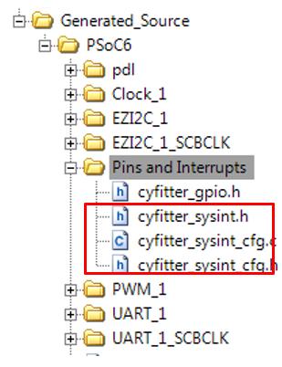
Building the project generates code for use in the application. The Pins and
Interrupts folder contains files with code generated using the information
entered in the Interrupts tab in CyDWR.
Cyfitter_sysint.h contains macros with information on interrupt number,
its CPU assignment, and priority.
Cyfitter_sysint_cfg.c/h declares and pre-populates instances of
SysInt PDL configuration structure using the CyDWR
information.
The configuration structure for each interrupt is conditionally defined based on the CPU assignment.
The steps to enable interrupts in firmware are similar to the ones listed in the PDL section but fewer in number.
Call the __enable_irq()API to enable global interruptsCall Cy_SysInt_Init(&SysInt_1_cfg, ISR_1_handler)- Where
SysInt_1_cfgis the name of the auto-generated structure from the cyfitter_sysint_cfg.c file.ISR_1_handleris the name of the interrupt handler that executes when the interrupt triggers. The handler function can reside in the respective CPU’s main.c to which the interrupt is assigned. If the handler exists outside main.c, that file must be compiled and linked into the executable for the CPU that handles the ISR - This step configures the interrupt (routing, priority, and interrupt handler assignment) but does not enable it
- Where
Call NVIC_ClearPendingIRQ(SysInt_1_cfg.intrSrc)to clear any pending interruptsCall NVIC_EnableIRQ(SysInt_1_cfg.intrSrc)to enable the interrupt
You can use PSoC™ Creator to generate code, and import that into a preferred IDE. AN219434 – Importing PSoC™ Creator Code into an IDE for a PSoC™ 6 MCU Project describes how to do that. It is recommended that you use PSoC™ Creator to set up and configure interrupts in PSoC™ 6 MCU, export the project to the IDE you prefer and continue developing firmware code with the IDE preferred.
Debugging tips
This section provides tips on trouble-shooting and debugging interrupts. The following are some of the frequently encountered cases:
- Interrupt is not triggered
- Ensure that the interrupt source and global interrupt are enabled
- Ensure that the interrupt vector is initialized with correct ISR
- Check whether other interrupt sources are triggered repeatedly, so consuming the entire CPU bandwidth
Interrupt is triggered repeatedly
This can happen in multiple cases: Insert breakpoints in the ISR and elsewhere in the program which is expected to execute repeatedly (for example, the super-loop in the main function). If the program is not entering the main function, interrupt is triggered repeatedly
The interrupt line from a fixed-function source
Resolution: Clear the interrupt source to resolve this behavior
A digital output from the Component (not the interrupt line) is connected to a SysInt Component configured to level type in PSoC™ Creator
Resolution: Configure the Interrupt Component to rising for example to get one interrupt per rising edge.
Execution of the ISR is taking longer than expected
This can happen if other high-priority interrupts are triggered during the execution of the ISR.
Resolution: Increase the priority of the interrupt relative to other interrupt sources.
The PSoC™ 6 BLE Pioneer Kit has the KitProg2 onboard programmer/debugger.
The CY8CPROTO-062-4343W PSoC™ 6 Wi-Fi BT Prototyping Kit has the KitProg3 onboard programmer/debugger. This kit is supported only on ModusToolbox™.
PSoC™ Creator supports debugging one CPU at a time (either CM0+ or CM4). ModusToolbox™ IDE supports debugging of both CPUs simultaneously.
The debug mode is useful for checking interrupts as given below:
- To check if an interrupt is executing, add a breakpoint at one of the instructions in the ISR
- Use Breakpoint Hit Count/breakpoint condition to detect the number of times an interrupt is triggered. This is particularly useful to check if the interrupt signal has glitches causing the interrupt to trigger multiple times. To see Breakpoint Hit Count, right-click on the breakpoint, select Hit Count and observe current hit count.
- Use the Call Stack window of the debugger to check program flow to learn when a particular ISR is executed. You can also use it to check if a high-priority interrupt occurred during the execution of a low-priority ISR
- As an alternative to the debugger, you can also use a pin to do the following:
- Check if the CPU is entering the ISR
- Measure the ISR execution time. This can be done, for example, by asserting the pin in the beginning of the ISR and de-asserting the pin before returning from the ISR. The time for which the pin is HIGH can be measured using an oscilloscope to give the duration of ISR execution
Advanced interrupt topics
Exceptions
Exceptions are the events that cause the processor to suspend the currently executing code and branch to a handler. Interrupts are a subset of exceptions. Besides interrupts, exceptions exist for operating system applications and fault handling.
| Exception | Exception number | Exception priority | CPUs supporting the exception | Description |
|---|---|---|---|---|
Reset | 1 | -3 | Both CM0+ and CM4 | This exception can occur due to multiple reasons, such as power-on-reset (POR), external reset signal on XRES pin, or watchdog reset. Cortex®-M4 execution begins only after CM0+ de-asserts the M4 reset. The reset exception address in the SRAM vector table will never be used because the device comes out of reset with the flash vector table selected. The register configuration to select the SRAM vector table can be done only as part of the startup code in flash after the reset is de-asserted. |
Nonmaskable Interrupt (NMI) | 2 | -2 | Both CM0+ and CM4 | Both CPUs have their own NMI exception. NMI can be triggered by the following: Any of the interrupt sources, by setting NMIPENDSET bit or using System Calls. PSoC™ 6 BLE supports routing of only one system interrupt as the source for NMI. CY8C62x8/A supports four system interrupt sources for NMI. The four selected interrupt sources are logically Ored into a single CPU NMI input NMI exception handler address is automatically initialized to the system call API located in SROM (at 0x0000000D by the boot code. The value should be retained by the user during vector table relocations; otherwise, no system call will be executed. |
HardFault Exception | 3 | -1 | Both CM0+ and CM4 | HardFault exception occurs when executing an undefined instruction or accessing an invalid memory addresses. |
SVCall Exception | 11 | Configurable | Both CM0+ and CM4 | Supervisor Call (SVCall) is an always-enabled exception caused when the CPU executes the SVC instruction as part of the application code. The SVC instruction enables the application to issue a supervisor call that requires privileged access to the system. |
PendSV | 14 | Configurable | Both CM0+ and CM4 | PendSV exception is normally software-generated. PendSV is another supervisor call related exception similar to SVCal. |
SysTick Exception | 15 | Configurable | Both CM0+ and CM4 | SysTick is a 24-bit decrementing counter that generates periodic interrupts. |
Memory Management Fault Exception | 4 | Configurable | Only CM4 | A memory management fault is an exception that occurs because of a memory protection-related fault. |
Bus Fault Exception | 5 | Configurable | Only CM4 | A Bus Fault is an exception that occurs because of a memory-related fault for an instruction or data memory transaction. |
Usage Fault Exception | 6 | Configurable | Only CM4 | A Usage Fault is an exception that occurs because of a fault related to instruction execution. |
Note:
- Exception priority that are configurable can be configured from priority 0-3 for CM0+ and 0-7 for CM4.
- Interrupts are also part of exceptions. Interrupt vector number 0 (i.e., IRQ 0) corresponds to the exception number 16, and so on.
Interrupt latency
Interrupt latency is defined as the time delay between the assertion of an interrupt and the execution of the first instruction in its ISR. CM0+ has a latency of 15 clock cycles (worst case); CM4 has a latency of 12 clock cycles (worst case). Some peripherals generate additional cycles due to synchronization circuit between the peripherals and CPUs. Table 3 provides the number of CPU clock cycle delays for various peripherals in PSoC™ 6 MCU.
| Interrupt source | Synchronization delay |
|---|---|
TCPWM, DMA, USB, I2S, PDM – PCM, CDS | 0 clock cycles |
SCB, GPIO, LPComp, RTC, WDT, SMIF, BLE | 2 clock cycles |
When both CPUs are in sleep/deep sleep power mode, there is a need for additional two clock cycles required for synchronization.
Context switching affects the latency and involves the following steps:
- Current instruction execution is completed
- The processor pushes the current Program Counter (PC), Link Register (LR), Program Status Register (PSR), and some of the general-purpose registers (Program and Status Register (PSR), Return Address, Link Register (LR or R14), R12, R3, R2, R1, and R0) to the stack
- The processor reads the vector address from the NVIC and updates it to the PC
- The processor updates the NVIC registers
Thus, the latency varies depending on the current instruction being executed. To make the process efficient, both CM0+ and CM4 processors implement the following two schemes:
Tail Chaining: If an interrupt is in the pending state while the processor is executing another interrupt handler, unstacking is skipped when the execution ends for the first interrupt and the handler for the pending interrupt is immediately executed. This saves the time of restoring the registers from the stack and pushing the same registers again to stack. This is useful for nested interrupts, as seen in the following section, and for reducing the latency of low-priority interrupts.
Figure 12.
Tail chaining

Late Arrival: If a higher-priority interrupt occurs during the stacking process of a lower-priority interrupt, the processor jumps to the higher-priority interrupt handler instead of a lower-priority one. The processor reads the vector address of the higher-priority interrupt at the end of the stacking process. Once the higher-priority interrupt handler execution is completed, the vector address for the pending lower-priority interrupt handler is fetched and executed. This reduces the latency for a higher-priority interrupt by entering the lower priority ISR and pushing the register values to the stack.
Figure 13.
Late arrival

Nested interrupts
NVIC automatically handles nested interrupts without any software overhead. If a higher-priority interrupt is asserted during the execution of a lower-priority interrupt handler, some of the general-purpose registers are pushed to stack, CPU reads the vector address from NVIC and jumps to the higher-priority interrupt handler. After the execution is completed, the processor restores the register values and execution resumes for the lower-priority interrupt.
Code optimization
An important performance requirement in interrupt-based applications is the ISR code execution time. In some applications, the critical code in the ISR must be executed within a particular time of receiving the interrupt request. Also, interrupt execution should not take too much time and stall the main code execution or other interrupts. To meet these requirements, use the following guidelines:
- Avoid calls to lengthy functions in the ISR. Functions such as Character LCD display routines or printing long strings to a UART terminal takes long time to execute, so blocking the execution of other low-priority interrupts. The recommended technique is to move non-critical function calls to the main code and just set a flag variable in the ISR. The main code periodically checks the flag and if set, clears it and calls the function
- Assign proper priority to the interrupts. In applications with multiple interrupts, give a higher priority to more time-critical interrupts
Although AN89610 – PSoC™ 4 and PSoC™ 5LP ARM Cortex® Code Optimization targets a different CPU architecture, it is a useful reference for general compiler topics.
References
For a complete and updated list of PSoC™ 6 MCU code examples, visit our code examples web page . For more PSoC™ 6 MCU-related documents, please visit our PSoC™ 6 MCU product web page.
| Document | Document name |
|---|---|
| Application notes | |
Getting Started with PSoC™ 6 MCU on ModusToolbox™. | |
| AN221774 | Getting Started with PSoC™ 6 MCU on PSoC™ Creator |
Getting Started with PSoC™ 6 MCU with Bluetooth® Low Energy (BLE) Connectivity | |
| AN215656 | PSoC™ 6 MCU Dual-CPU System Design |
| AN219434 | Importing PSoC™ Creator Code into an IDE for a PSoC™ 6 MCU Project |
Programmable digital | |
PSoC™ 6 MCU GPIO Interrupt | |
PSoC™ 6 MCU Hello World Example | |
PSoC™ 6 MCU: SCB UART Transmit and Receive with DMA | |
PSoC™ 6 MCU: SCB SPI Master with DMA | |
PSoC™ 6 MCU Watchdog Timer | |
PSoC™ 6 MCU: CAPSENSE™ Buttons and Slider | |
PSoC™ 6 MCU: CSD Analog-to-Digital Converter (ADC) | |
PSoC™ 6 MCU: CAPSENSE™ Custom Scan | |
PSoC™ 6 MCU: CAPSENSE™ Buttons and Slider (FreeRTOS) | |
PSoC™ 6 MCU with Bluetooth™ Low Energy (BLE) Connectivity: Find Me Application | |
PSoC™ 6 MCU with BLE Connectivity: Battery Level (FreeRTOS) | |
PSoC™ 6 MCU: BLE Throughput Measurement (FreeRTOS) | |
PSoC™ 6 MCU: USB Audio Device with FreeRTOS | |
PSoC™ 6 MCU: USB CDC Echo Application | |
PSoC™ 6 MCU: USB HID Mouse Application | |
PSoC™ 6 MCU: USB HID Generic Application | |
| mtb-example-psoc6-usb-msc-file-system | PSoC™ 6 MCU: USB Mass Storage File System |
PSoC™ 6 MCU: USB Mass Storage Logger | |
PSoC™ 6 MCU - GPIO Interrupt | |
PSoC™ 6 MCU Dual-Core Basics | |
PSoC™ 6 MCU Wake up from hibernate Using Low-Power Comparator | |
PSoC™ 6 Custom Tick Timer Using RTC Alarm Interrupt | |
PSoC™ 6 MCU MCWDT and RTC Interrupts (Dual Core) | |
| CE220061 | PSoC™ 6 MCU Multi-Counter Watchdog Interrupts |
PSoC™ 6 MCU Watchdog Timer in interrupt mode | |
PSoC™ 6 MCU Periodic Interrupt Using TCPWM | |
PSoC™ 6 MCU with Bluetooth™ Low Energy (BLE) Connectivity - Find Me | |
Software/IDE | |
PDL API Reference available on installation | |
Appendix A. Interrupt sources in PSoC 6 MCU
For information on IRQ number and applicable power mode for each interrupt, see the “Interrupts” chapter of the respective devices’ technical reference manual.
| Interrupt source | Details |
|---|---|
| GPIOs | Each port consists of a maximum of eight pins. Each pin can generate an interrupt, but the vector address is common for all pins in a port. Firmware must identify the pin that caused the interrupt. PSoC™ 6 MCU enables interrupt trigger on the rising edge, falling edge, or both edges of the GPIO signal. This interrupt can wake the device from sleep, deep-sleep modes. |
| There is a GPIO All Ports interrupt that allows combining all port interrupts into a single vector. Firmware must identify the port that caused the interrupt. | |
| There is a GPIO Supply Detect Interrupt that can be used to detect the supply ramping up or ramping down. | |
| LPComp | Like GPIOs, an interrupt can be triggered on the rising edge, falling edge, or both edges of the comparator output signal. LPComp can also wake the device from sleep, deep sleep, and hibernate power modes. |
| SCB (deep sleep) | SCB interrupt that can wakeup CPU/system from deep sleep |
| Multi Counter Watchdog Timer (MCWDT) Interrupt | MCWDT configures two 16-bit counters and one 32-bit counter capable of generating periodic interrupts. MCWDT can wake the CPU from deep sleep power mode. |
| Backup Domain Interrupt | Backup domain interrupt includes the RTC ALARM1, RTC ALARM2, and RTC century overflow interrupt. This can be used to wake the CPU from sleep, deep sleep, and hibernate power modes. |
| Other Combined Interrupts for SRSS | The following cases generate this interrupt: WDT interrupt, Low Voltage Detect (LVD) interrupt, and clock calibration interrupt. WDT interrupt occurs when the watchdog counter value matches the preset Counter Match value. Missing two interrupts will cause a watchdog reset. Low-voltage detect (LVD) interrupt when the device supply voltage drops below a threshold. Clock calibration interrupt is triggered when clock calibration is complete. These are capable of waking the CPU from deep sleep. |
| CTBm Interrupt (all CTBms) | This block provides continuous time analog functionality. It generates interrupts on event such as comparator triggers. |
| Bluetooth Radio Interrupt | Bluetooth sub-system interrupt |
| IPC Interrupt | IPC interrupts could be triggered when an IPC release or notify event occurs. |
| SAR ADC | |
| CTBm Interrupt (individual CTBm) | This block provides continuous time analog functionality. It generates interrupts on event such as comparator triggers. |
| PASS FIFO Interrupt | |
| SCB | PSoC™ 6 MCU supports SCBs which can be configured as SPI, I2C or UART. One SCB interrupt amongst the 8 SCBs is deep sleep-capable. The following events generate an interrupt in a SCB.
|
| CSD (CAPSENSE™) Interrupt | CSD, used for touch applications, generates an interrupt when the sensor scan is complete. |
| CPUSS DMAC, Channel #0 – 3 | DMA Controller (DMAC) interrupts on DMA events like transfer completion, bus errors, address misalignments, current pointer being NULL, active channel disabled and descriptor error. |
| DMA Interrupt | DMA interrupt can be generated when the data transfer is completed. |
| CPUSS Fault Structure Interrupt #0 | This interrupt occurs when there is a protection unit access violation. |
| CRYPTO Accelerator Interrupt | Crypto Interrupt is generated in the following cases: When a FIFO event is activated, FIFO overflows, true random number generator is initialized, true random number generator has generated a data value of the specified bit size, pseudo random number generator has generated a data value, instruction decoder encounters an instruction with a non-defined operation code, instruction decoder encounters an instruction with a non-defined condition code, when a AHB-Lite bus error is observed, true random number generator monitor adaptive proportion test detects a repetition of a specific bit value, true random number generator monitor adaptive proportion test detects a disproportionate occurrence of a specific bit value. |
| FLASH Macro Interrupt | Flash controller has a timer that generates interrupts. |
| Floating point interrupt | Floating Point operation fault |
| CM0+ CTI #0 | CTI triggers are used to communicate events between debug components. |
| CM4 CTI #0 | CTI triggers are used to communicate events between debug components. |
| TCPWM | The TCPWM block can be configured to work as a 16- or 32-bit timer, counter, or PWM. It can generate interrupts on terminal count, input capture signal, or a compare true event. |
| UDB Interrupt #0 | Any digital signal generated in a UDB can trigger an interrupt. Signals are routed to the interrupt controller through the routing fabric known as Digital System Interconnect (DSI). |
| I2S Audio Interrupt | Interrupt can be generated in the following cases. Less entries in the TX FIFO than the value specified, TX FIFO is not full, TX FIFO is empty, attempt to write to a full TX FIFO, attempt to read from an empty TX FIFO, triggers when the Tx watchdog event occurs, more entries in the RX FIFO than the value specified , RX FIFO is not empty, RX FIFO is full, attempt to write to a full RX FIFO, attempt to read from an empty RX FIFO, triggers when the Rx watchdog event occurs. |
| PDM/PCM Audio interrupt | More entries in the RX FIFO than the value specified, RX FIFO is not empty, attempt to write to a full RX FIFO, attempt to read from an empty RX FIFO |
| Energy Profiler Interrupt | This interrupt occurs on a profiling counter overflow. |
| Serial Memory Interface Interrupt | This interrupt is activated when TX data FIFIO is activated, RX data FIFO is activated, alignment error, FIFIO overflow. |
| USB Interrupt | The USB block has a predefined set of 13 interrupt trigger events that can be mapped to either one of the three interrupts. Events such as USB Start of Frame (SOF), USB bus reset, data endpoint events, control endpoint events, Arbiter Interrupt Event, and Link Power Management (LPM) event generate interrupts. |
| CAN Interrupt | CAN consolidated or individual channel interrupt |
| Consolidated Interrupt for all DACs | Interrupt can be generated when DAC buffer is empty. This interrupt can be used by the CPU to transfer the next value to the DAC. |
| SDIO wakeup Interrupt for SDHC | SDIO wakeup interrupt triggered on events such as card insertion, removal, and SDIO card interrupt. This doesn’t wakeup the system from deep sleep. |
| Consolidated Interrupt for SDHC | Consolidated interrupt on all other normal/error events related to SDHC |
| EEMC Wakeup Interrupt for mxsdhc, not used | EEMC wakeup interrupt for SDHC block (reserved) |
| Consolidated Interrupt for SDHC | Consolidated interrupt (reserved) |
Revision history
| Document version | Date of release | Description of changes |
|---|---|---|
** | 2017-09-15 | New Application Note |
*A | 2018-11-08 | Updated for CY8C62x8/A and ModusToolbox™ |
*B | 2019-02-25 | Updated section “Configuring Interrupts Using ModusToolbox™” |
*C | 2019-10-21 | Sunset review Updated section “Configuring Interrupts Using ModusToolbox™” |
*D | 2020-07-29 | Updated information for CY8C61x6/7, CY8C62x4, and CY8C62x5 devices Updated References |
*E | 2021-03-27 | Migrated to new template. |
| *F | 2022-07-21 | Template update |