AN228571 Getting started with PSOC™ 6 MCU on ModusToolbox™ software
About this document
Scope and purpose
This application note introduces the PSOC™ 6 microcontroller (MCU), a low power, secured MCU with dual CPU Arm® Cortex®-M4 and Cortex®-M0+
processors. This application note helps you explore the PSOC™ 6 architecture and
development tools and shows you how to create your first application using
ModusToolbox™ software. This application note also guides you to more resources
available online to accelerate your learning about PSOC™ 6 .
Intended audience
This document is intended for the users who are new to
PSOC™ 6
and ModusToolbox™ software.
Associated part family
All
PSOC™ 6
devices
Software version
3.2 or above.
More code examples? We heard you.
To
access an ever-growing list of PSOC™ 6 code examples using ModusToolbox™, please visit the GitHub site
.
Introduction
PSOC™ 6 MCU is an ultra-low-power PSOC™ device with a dual-core architecture and low-power design techniques tailored for battery-powered applications. The dual-core Arm® Cortex®-M4 and Cortex®-M0+ architecture lets designers optimize for power and performance simultaneously. With integrated on-chip flash/SRAM memory, encrypted external flash memory expansion, configurable memory and peripheral protection units, and a cryptographic accelerator, the PSOC™ 6 MCU supports standard embedded security features like secured boot, secured provisioning, secured key storage, run-time security, and secured firmware updates.
Designers can use the MCU’s rich analog and digital peripherals to create custom analog front-ends (AFEs) or digital interfaces for innovative system components such as MEMS sensors and electronic-ink displays. The PSOC™ 6 MCU features the fourth generation of industry-leading CAPSENSE™ capacitive-sensing technology, enabling modern touch and gesture-based interfaces that are robust and reliable. PSOC™ 6 MCU, paired with Infineon’s AIROC™ Wi-Fi, AIROC™ Bluetooth®, or AIROC™ combo radio modules, is the perfect solution for secure, low-power, feature-rich IoT products.
Due to the versatile features of the PSOC™ 6 MCU, it can be used in a wide variety of applications, spanning consumer electronics, industrial applications, smart homes, IoT, and general-purpose embedded applications.
PSOC™ 6 architecture and portfolio overview
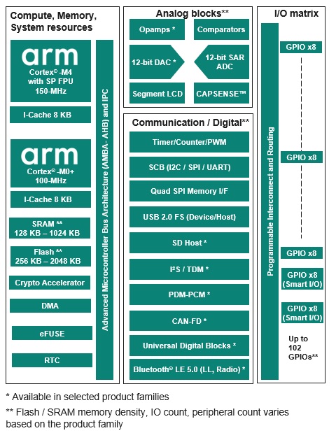
The PSOC™ 6 architecture block diagram, as shown in the following figure, is a unified block diagram covering the entire PSOC™ 6 MCU portfolio. Refer to the respective product family datasheets for the features offered for a specific device in the PSOC™ 6 portfolio. For example, Flash/SRAM memory density, IO count, peripheral features/count, and supported packages vary based on the product family chosen in the PSOC™ 6 portfolio.
Figure 1. PSOC™ 6 architecture
PSOC™ 6 MCU portfolio segmentation
The PSOC™ 6 MCU portfolio consists of multiple product families, which fall under four different product lines.
PSOC™ 61 (Programmable line)
consists of product families in which only the Arm® Cortex® M4 is available for user applications. Orderable part numbers (OPN) in the PSOC™ 61 line start with the “CY8C61” prefix
PSOC™ 62 (Performance line)
consists of product families in which both the Arm® Cortex® M4 and Arm® Cortex®-M0+ are available for user applications (dual CPU architecture). Orderable part numbers (OPN) in thePSOC™ 62 line start with the “CY8C62” prefix
PSOC™ 63 (Connectivity line)
consists of product families that include the Bluetooth® LE radio PHY and MAC integrated as part of the MCU. Orderable part numbers (OPN) in the PSOC™ 63 line start with the “CY8C63” prefix
PSOC™ 64 (Secured line)
consists of product families in which the Arm® Cortex® M0+ is configured as a secured processing environment (SPE) and the Arm® Cortex® M4 acts as a non-secured processing environment (NSPE). Orderable part numbers (OPN) in the PSOC™ 64 line start with the “CYB064” or “CYS064” prefix. This product family is primarily intended for applications that require secured factory provisioning of the firmware, including security keys and certificates
Device features
PSOC™ 6 MCUs have extensive features, as shown in
Figure 1
. The following is a list of major features. For more information, see the device
datasheet
, the
technical reference manual (TRM)
, and
References
section.
High-performance, low-power compute system
Dual-core architecture: 150-MHz Arm® Cortex®-M4, and 100-MHz Arm® Cortex®-M0+
On-chip memory: up to 1024 KB SRAM, up to 2048 KB flash
Ultra-low-power (0.9 V) and low-power (1.1 V) operation modes
Multiple device low power modes: Hibernate, Deep Sleep, Sleep, and Active. Low-power analog operation
Robust security features
Advanced cryptographic accelerator and true random number generator
One-time programmable eFUSE for secure key storage
Secured boot, secured provisioning, and image authentication
Secure over-the-air (OTA) firmware update with read-while-write flash technology for firmware updates
Integration
4 th generation CAPSENSE™ to integrate a robust touch user interface into a single MCU
Segment LCD drive, serial interface display drivers
Quad SPI Memory I/F for memory expansion
Smart I/O to integrate external digital glue logic in the MCU
Universal Digital Blocks (UDBs) to implement CPLD and mini-FPGA logic in MCU
Rich analog peripherals
12-bit SAR ADC, 12-bit DAC, OpAmps, low-power comparators. Low-power analog operation
Digital blocks and communication interfaces
Highly configurable 16-bit and 32-bit timers, counters, and PWMs
Serial Communication Blocks (I2C/SPI/UART) for digital sensor/host MCU interfaces
I2S/TDM, PDM-PCM converter for audio applications
SD Host Controller (SDHC), USB 2.0 full speed (host and device)
CAN-FD for industrial applications
Wide variety of IO and package options
124-BGA, 100-WLCSP, 80-WLCSP, 80-M-CSP, 49-WLCSP, 68-QFN, 128-TQFP, 100-TQFP, 80-TQFP, 64-TQFP
Up to 102 GPIOs
-40 to 85°C operation with support for extended temperature operation (105°C) in select devices
Target applications
The versatile, secured, low-power, feature-rich offerings in the PSOC��™ 6 MCU make it the ideal choice of microcontroller for a wide variety of end applications. Some of these applications are listed below.
Wearable devices like smart watches and fitness trackers
Smart home devices like smart locks, thermostats, and integrated alarm systems
Smart home appliances like washing machines, refrigerators, and cooktops
Datacenter and computing applications for the system management function
Power tools, e-bikes, and other motor control applications
Industrial IoT applications
Battery powered devices
The following figure illustrates an application-level block diagram for a real-world use case using PSOC™ 6 MCU.
Figure 2. Application-level block diagram using PSOC™ 6 MCU
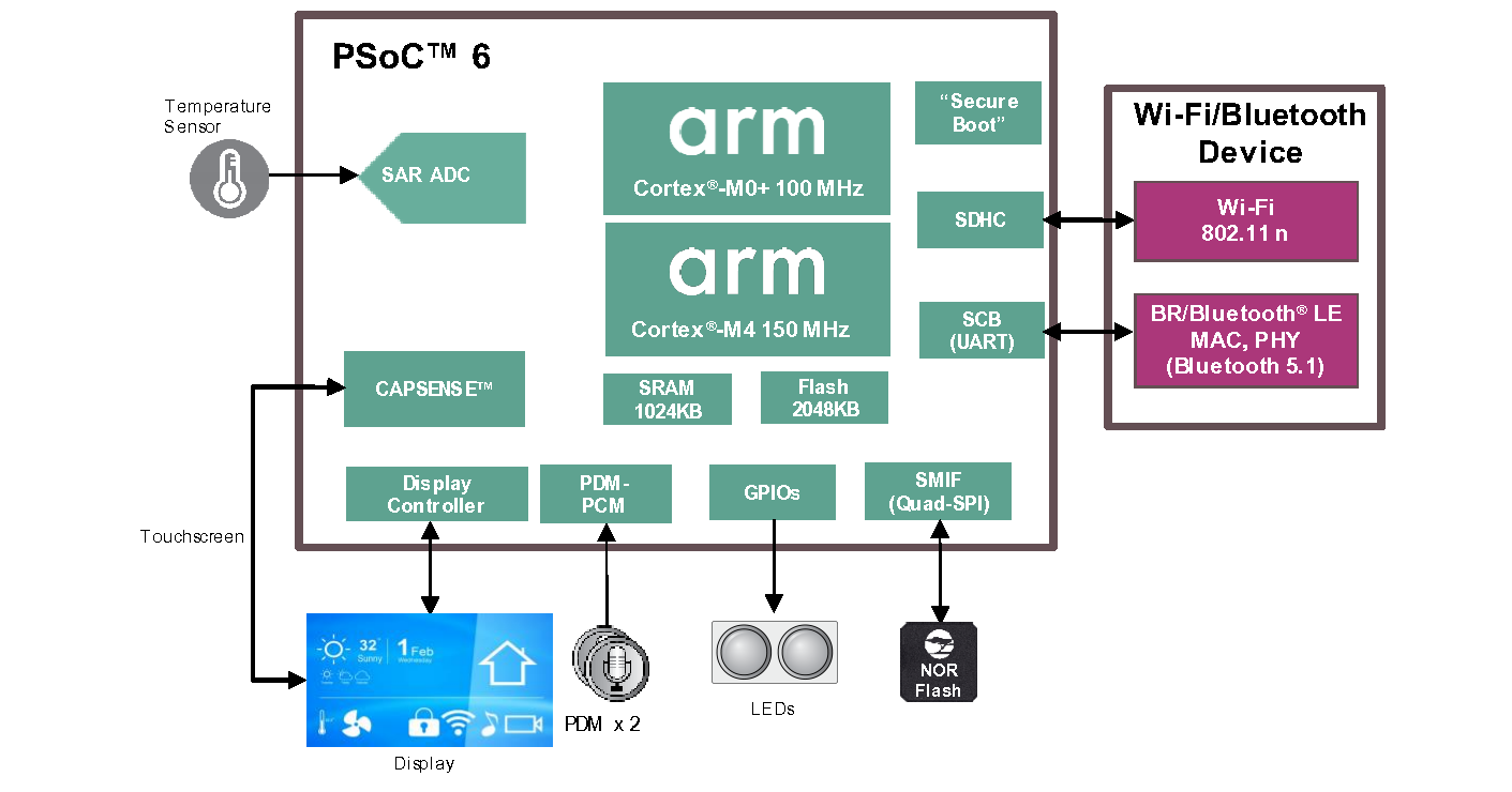
Depending on the end application use case, the PSOC™ 6 MCU can perform a wide variety of system functions, as listed below.
Main system application MCU
Wi-Fi MCU integrating analog front end (AFE), CAPSENSE™ (touch), display, and audio functionality
Low-power sensor co-processor to Arm® A-class based SoCs and MPUs
Motor control MCU with integration of CAPSENSE™ (touch) and other user interface features
System management controllers like fan control, power sequencing, and server backplane management
PSOC™ 6·resources
A wealth of technical resources are available to develop applications with PSOC™ 6 4. These resources are listed below.
- PSOC™ 6 video library
PSOC™ 6 webpage
Product selectors: PSOC™ 6
Datasheets describe and provide electrical specifications for each device family.
Application notes and Code examples cover a broad range of topics, from basic to advanced level. You can also browse our collection of code examples.
Technical reference manuals (TRMs) provide detailed descriptions of the architecture and registers in each device family.
PSOC™ 6 programming specification provides the information necessary to program the nonvolatile memory of PSOC™ 6 devices.
CAPSENSE™ design guides : Learn how to design capacitive touch-sensing applications with PSOC™ devices.
Development tools: Many low-cost kits and shield boards are available for evaluation, design, and development of different applications using PSOC™ 6 s.
Training videos: Video training on our products and tools, including a dedicated series on PSOC™ 6 s.
Technical Support: PSOC™ 6 community forum , Knowledge base articles .
PSOC™ 6 development kits
Infineon provides a wide variety of hardware development kits in various form factors to enable easy and rapid evaluation and prototyping of PSOC™ 6 based applications. The prototyping kits are low-cost, small-form factor evaluation kits for prototyping applications that do not need additional hardware shields to be connected to the kit. The Pioneer/Evaluation kits are more full featured kits that provide various hardware expansion capabilities, like the Arduino shield and M.2 interface for wireless radio interface.
The following table lists the PSOC™ 6 kits for the various product families. For a general evaluation of the PSOC™ 6 MCU portfolio, it is recommended to either use the super-set PSOC™ 6 prototyping kit (CY8CPROTO-062S2-43439) or the super-set PSOC™ 6 Pioneer kit (CY8CKIT-062S2-43012). ModusToolbox™ software is the software development platform for creating embedded applications using the development kits.
Kit MPN | Applicable PSOC™ 6 product families | Kit type | Board support package GitHub repository |
|---|---|---|---|
CY8CPROTO-062S2-43439 (Default recommended Proto kit) | CY8C61x8, CY8C61xA, CY8C62x8, CY8C62xA | prototyping | BSP |
CY8CKIT-062S2-43012 (Default recommended Pioneer kit) | CY8C61x8, CY8C61xA, CY8C62x8, CY8C62xA | Pioneer | BSP |
CY8CEVAL-062S2 | CY8C61x8, CY8C61xA, CY8C62x8, CY8C62xA | Evaluation | BSP |
CY8CKIT-062S4 | CY8C61x4, CY8C62x4 | Pioneer | BSP |
CY8CPROTO-062S3-4343W | CY8C61x5, CY8C62x5 | prototyping | BSP |
CY8CKIT-062-WIFI-BT | CY8C61x6, CY8C61x7, CY8C62x6, CY8C62x7 | Pioneer | BSP |
CY8CPROTO-064B0S3 | CYB064x5 | prototyping | BSP |
CY8CPROTO-064S1-SB | CYB064x7 | prototyping | BSP |
CY8CKIT-064B0S2-4343W | CYB064xA | Pioneer | BSP |
For the complete list of kits for the
PSOC™ 6
along with the shield modules, see the
Microcontroller (MCU) kits
page.
PSOC™ 6 software ecosystem and for firmware/application development
Infineon provides the ModusToolbox™ software for firmware/application development
based
on
PSOC™ 6
software
MCUs. ModusToolbox™ Software is a modern, extensible development ecosystem supporting a wide range of Infineon microcontroller devices, including PSOC™ Arm® Cortex® Microcontrollers, TRAVEO™ T2G Arm® Cortex® Microcontroller, XMC™ Industrial Microcontrollers, AIROC™ Wi-Fi devices, AIROC™ Bluetooth® devices, and USB-C Power Delivery Microcontrollers. This software includes configuration tools, low-level drivers, middleware libraries, and other packages that enable you to create MCU and wireless applications. All tools run on Windows, macOS, and Linux. ModusToolbox™ includes an Eclipse IDE, which provides an integrated flow with all the ModusToolbox™ tools. Other IDEs such as Visual Studio Code, IAR Embedded Workbench and Arm® MDK (μVision) are also supported.
ModusToolbox™ software
supports stand-alone device and middleware configurators. Use the
configurators to set the configuration of different blocks in the device and
generate code that can be used in firmware development.
Libraries and enablement
software are available at the GitHub site.
ModusToolbox™ tools and resources can also be used on the command line. See the build system chapter in the
ModusToolbox™ tools package user guide
for detailed documentation.
Installing the ModusToolbox™ tools package
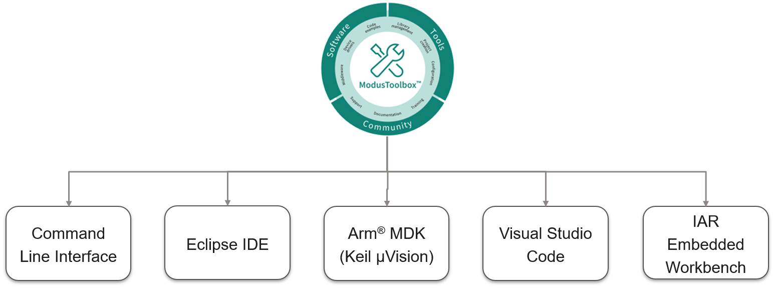
Choosing an IDE
ModusToolbox™ software, the latest-generation toolset, is supported across Windows, Linux, and macOS platforms. ModusToolbox™ software supports 3rd-party IDEs, including the Eclipse IDE, Visual Studio Code, Arm® MDK (μVision), and IAR Embedded Workbench. The tools package includes an implementation for all the supported IDEs. The tools support all
PSOC™ 6
s. The associated BSP and library configurators also work on all three host operating systems.
Figure 3. ModusToolbox™ environment
Getting started with PSOC™ 6 design
This section provides the following:
Demonstrate how to build a simple PSOC™ 6 -based design and program it on to the development kit
Makes it easy to learn PSOC™ 6 design techniques and how to use the ModusToolbox™ software with different IDEs.
Prerequisites
Before you get started, make sure that you have the appropriate development kit for your
PSOC™ 6
product line and have installed the required software. You also need internet to access the GitHub repositories during project creation.
Hardware
The example design shown below is developed for the
PSOC™
62S2 Wi-Fi Bluetooth® prototyping kit (CY8CPROTO-062S2-43439)
. However, you can build the application for other development kits. See the
PSOC 6 development kits
section for list of kits that you can use to get started with
PSOC™ 6
.
Software
3.2 or above.
After installing the software, see the
ModusToolbox™ tools package user guide
to get an overview of the software.
Using these instructions
These instructions are grouped into several sections. Each section is dedicated to a phase of the application development workflow. The major sections are:
Create a new application
View and modify the design configuration
Write firmware
Build the application
Program the device
Test your design
This design is developed for the
PSOC™
62S2 Wi-Fi Bluetooth® Prototyping Kit (CY8CPROTO-062S2-43439)
. You can use other supported kits to test this example by selecting the appropriate kit while creating the application.
About the design
This design uses the CM4 core of the
PSOC™ 6
to execute two tasks: UART communication and LED control.
At device reset, the Infineon-supplied pre-built CM0+ application image enables the CM4 core and configures the CM0+ core to go to sleep. The CM4 core uses the UART to print a “Hello World” message to the serial port stream, and starts blinking the user LED on the kit. When the user presses the enter key on the serial console, the blinking is paused or resumed.
Create a new application
This section takes you on a step-by-step guided tour of the new application process. It uses the
Empty App
starter application and manually adds the functionality from the
Hello World
starter application.
As mentioned in section
Choosing an IDE
, ModusToolbox™ software supports the following third-party IDEs:
The following sections provide details on how to create a new application on different IDEs.
Eclipse IDE for ModusToolbox™
If you are familiar with developing projects with ModusToolbox™ software, you can use the
Hello World
starter application directly. It is a complete design, with all the firmware written for the supported kits. You can walk through the instructions and observe how the steps are implemented in the code example.
If you start from scratch and follow all the instructions in this application note, you can use the
Hello World
code example as a reference while following the instructions.
Launch the
Dashboard 3.2
application to get started. Please note that the
Dashboard 3.2
application needs access to the internet to successfully clone the starter application onto your machine.
The
Dashboard 3.2
application helps you get started using the various tools with easy access to documentation and training material, a simple path for creating applications and creating and editing BSPs.
Open the Dashboard 3.2 application.
To open the
Dashboard 3.2
application, click
[ModusToolbox installation path]/ModusToolbox folder/dashboard 3.2.0
On the Dashboard 3.2 window, in the right pane, in the Target IDE drop-down list, select Eclipse IDE for ModusToolbox™ , and click Launch Eclipse IDE for ModusToolbox™
Figure 4. Dashboard 3.2 application
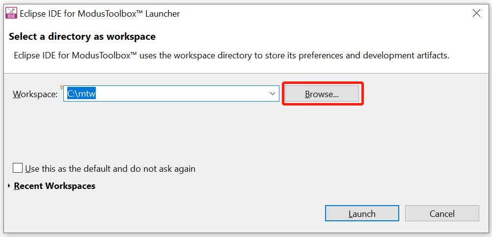
Select a new workspace.
At launch, Eclipse IDE for ModusToolbox™ presents a dialog to choose a directory for use as the workspace directory. The workspace directory is used to store workspace preferences and development artifacts. You can choose an existing empty directory by clicking the
Browse
button, as shown in the following figure. Alternatively, you can type in a directory name to be used as the workspace directory along with the complete path, and the IDE will create the directory for you.
Figure 5. Select a directory as the workspace
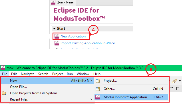
Create a new ModusToolbox™ application.
Click New Application in the Start group of the Quick Panel
Alternatively, you can choose , as shown in the following figure
The Project Creator opens.
Figure 6. Create a new ModusToolbox™ application
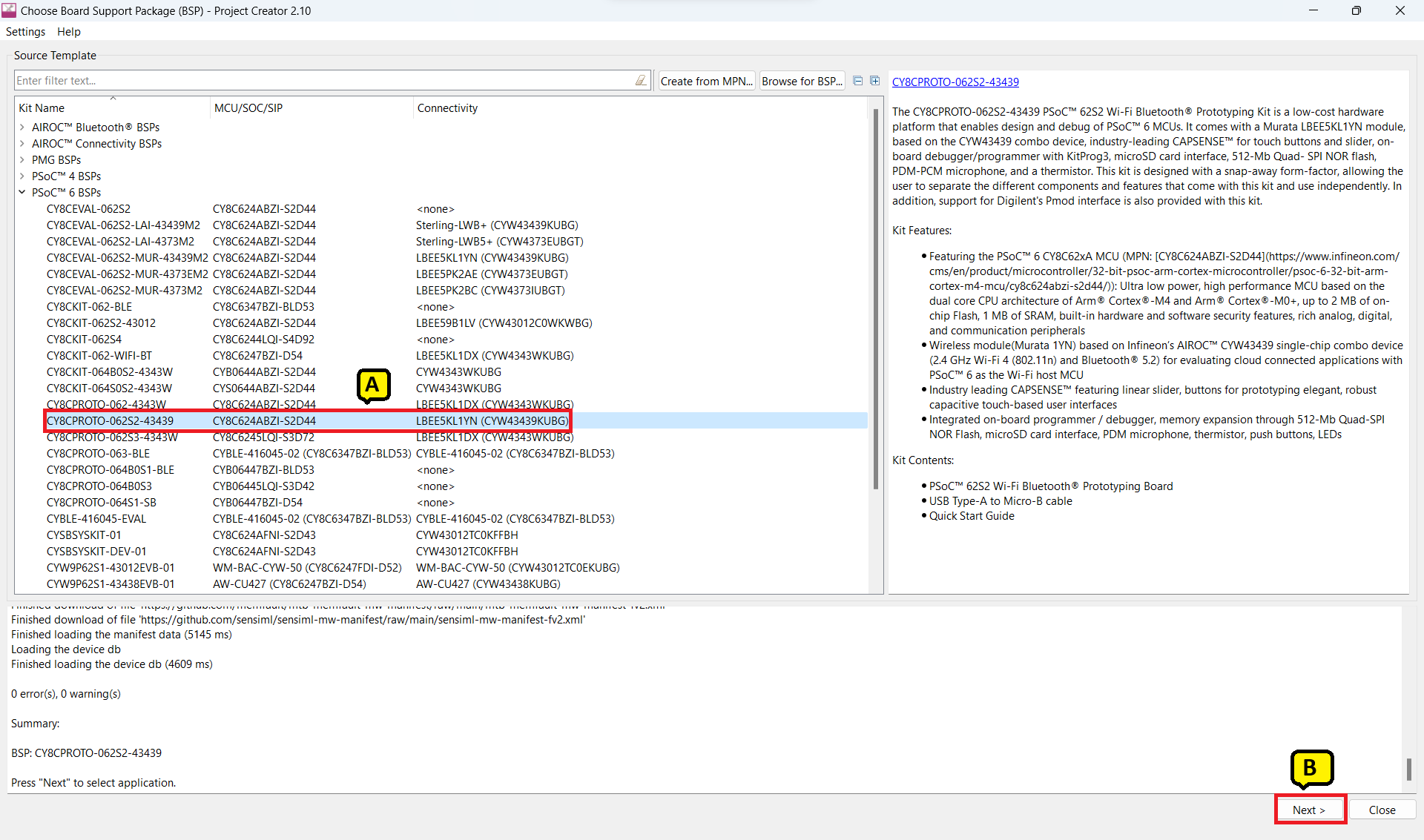
Select a target PSOC™ 6 development kit.
ModusToolbox™ speeds up the development process by providing BSPs that set various workspace/project options for the specified development kit in the new application dialog.
In the Choose Board Suppor Package (BSP) dialog, choose the Kit Name that you have. The steps that follow use CY8CPROTO-062S2-43439 . See Figure 7 for help with this step
Click Next
Figure 7. Choose target hardware
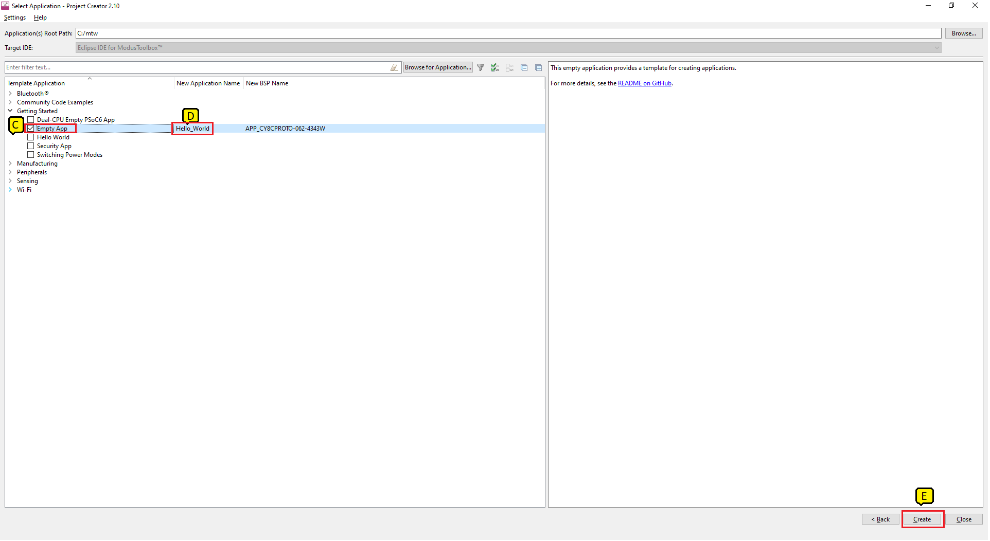
In the Select Application dialog, select Empty App starter application, as shown in the following figure
In the Name field, type in a name for the application, such as Hello_World . You can choose to leave the default name if you prefer
Click Create to create the application, as shown in the following figure, wait for the Project Creator to automatically close once the project is successfully created
Figure 8. Creating a new application
You have successfully created a new ModusToolbox™ application for a
PSOC™ 6
.
The BSP uses
CY8C624ABZI-D54
as the default device that is mounted on the
PSOC™ 6
2S2 Wi-Fi-Bluetooth® prototyping kit (CY8CPROTO-062S2-43439)
along with the CYW43439KUBG Wi-Fi/Bluetooth® radio
.
If you are using custom hardware based on
PSOC™ 6
or a different
PSOC™ 6
part number, refer to the
Custom BSP App Note
or the
BSP Assistant user guide
.
Refer to the
Eclipse IDE for ModusToolbox™
user guide for more information.
View and modify the design configuration
shows the Eclipse IDE Project Explorer interface displaying the structure of the application project.
A
PSOC™ 6
application consists of a project to develop code for the CM4 core. A project folder consists of various subfolders – each denoting a specific aspect of the project.
Figure 9. Project Explorer view
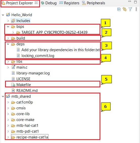
The files provided by the BSP are in the bsps folder and are listed under TARGET_<bsp name> subfolders. All the input files for the device and peripheral configurators are in the config folder inside the BSP. The GeneratedSource folder in the BSP contains the files that are generated by the configurators and are prefixed with cycfg_ . These files contain the design configuration as defined by the BSP. From ModusToolbox™ 3.x or later, you can directly customize configurator files of BSP for your application rather than overriding the default design configurator files with custom design configurator files since BSPs are completely owned by the application.
The BSP folder also contains the linker scripts and the start-up code for the
PSOC™ 6
used on the board.
The build folder contains all the artifacts resulting from a build of the project. The output files are organized by target BSPs.
The
deps
folder contains
.mtb
files, which provide the locations from which ModusToolbox™ pulls the libraries that are directly referenced by the application. These files typically each contain the GitHub location of a library. The
.mtb
files also contain a git Commit Hash or Tag that tells which version of the library is to be fetched and a path as to where the library should be stored locally.
For example, here, retarget-io.mtb points to
mtb://retarget-io#latest-v1.X#
/retarget-io/latest-v1.XThe variable
points to the root of the shared location which defaults to
mtb_shared
. If the library must be local to the application instead of shared, use
instead of
The libs folder also contains .mtb files. In this case, they point to libraries that are included indirectly as a dependency of a BSP or another library. For each indirect dependency, the Library Manager places a .mtb file in this folder. These files have been populated based on the targets available in deps folder.
For example, using BSP CY8CPRTO-062S2-43439 populates libs folder with the following .mtb files:
cmsis.mtb
,
core-lib.mtb
,
core-make.mtb
,
mtb-hal-cat1.mtb
,
mtb-pdl-cat1.mtb
,
cat1cm0p.mtb
,
recipe-make-cat1a.mtb
.
For example, using BSP KIT_PSC3M5_EVK populates the libs folder with the following
.mtb
files:
cmsis.mtb
,
core-lib.mtb
,
core-make.mtb
,
deivce-db.mtb
,
mtb-hal-psc3.mtb
,
mtb-pdl-cat1.mtb
,
receipe-make-cat1b
.
The
libs
folder contains the file
mtb.mk
, which stores the relative paths of all the libraries required by the application. The build system uses this file to find all the libraries required by the application.
Everything in the libs folder is generated by the Library Manager so you should not manually edit anything in that folder.
An application contains a Makefile which is at the application's root folder. This file contains the set of directives that the make tool uses to compile and link the application project. There can be more than one project in an application. In that case there is a Makefile at the application level and one inside each project.
See AN215656 - PSOC™ 6 MCU dual-core system design for details related to multi-project applications
By default, when creating a new application or adding a library to an existing application and specifying it as shared, all libraries are placed in an mtb_shared directory adjacent to the application directories.
The
mtb_shared
folder is shared between different applications within a workspace. Different applications may use different versions of shared libraries if necessary.
Open the Device Configurator and configure system
BSP configurator files are in the
bsps/TARGET_<BSP-name>/config
folder.
For example, click
Click
<Application-name>
from
Project Explorer
then click
Device Configurator
link in the
Quick Panel
to open the file
design.modus
in the
Device Configurator
as shown in the following figure. You can also open other configuration files in their respective configurators or click the corresponding links in the
Quick Panel
.
Figure 10. Device Configurator
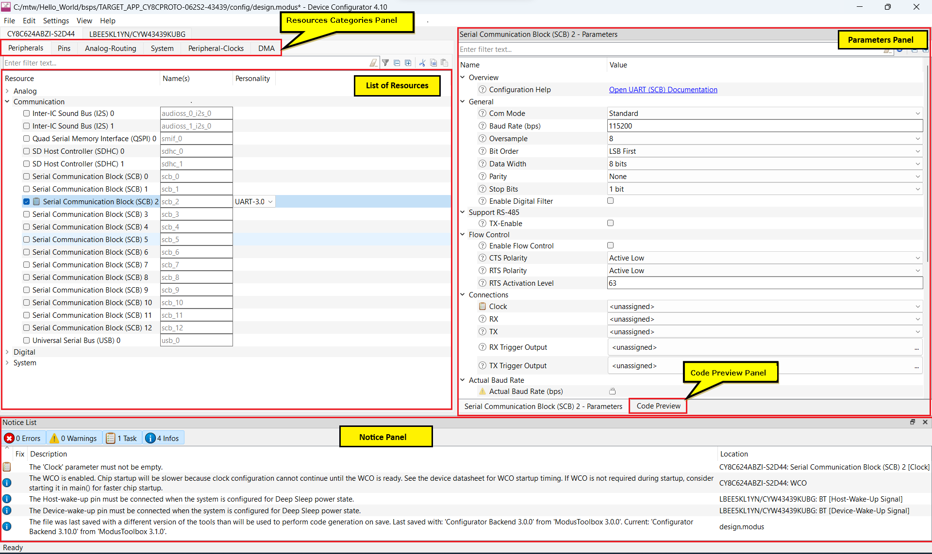
The
Device Configurator
provides a set of
Resources Categories
tabs. Here you can choose between different resources available in the device such as peripherals, pins, and clocks from the
List of Resources
.
You can choose how a resource behaves by choosing a
Personality
for the resource. For example, a
serial communication block (SCB)
resource can have
EZI2C
,
I2C
,
SPI
, or
UART
personalities. The
Alias
Name(s)
is your name for the resource, which is used in firmware development. One or more aliases can be specified by using a comma to separate them (with no spaces).
The
Parameters
pane is where you enter the configuration parameters for each enabled resource and the selected personality. The
Code Preview
pane shows the configuration code generated per the configuration parameters selected. This code is populated in the
cycfg_
files in the
GeneratedSource
folder. The Parameters pane and Code Preview pane may be displayed as tabs instead of separate windows but the contents will be the same.
Any errors, warnings, and information messages arising out of the configuration are displayed in the
Notices
pane.
Configuring the peripheral is required for both PDL and HAL based implementations to work.
Currently, the Device Configurator
supports configurations using the PDL source. If you choose to use HAL libraries in
your application, then you do not need to do any device configuration changes in
here.
The application project contains source files that help you create an application for the
CM4
core (for example,
main.c
)
, while the CM0+ application is supplied as a default
C
file (
psoc6_02_cm0p_sleep.c
for the
CY8C624ABZI-D44
device). See the
cat1cm0p
library
. This
C
file is compiled and linked with the
CM4
image as part of the normal build process.
At this point in the development process, the required middleware is ready to be added to the design. The only middleware required for the Hello World application is the
retarget-io
library.
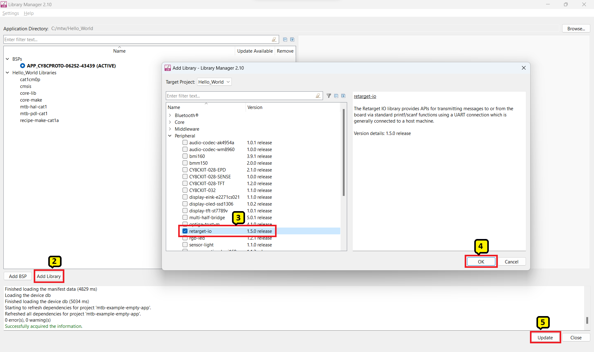
Add retarget-io middleware
In this section, you will add the retarget-io middleware to redirect standard input and output streams to the UART configured by the BSP. The initialization of the middleware will be done in main.c file.
In the Quick Panel , click the Library Manager link.
In the subsequent dialog, click Add Libraries .
Under Peripherals , select and enable retarget-io .
Click OK and then Update .
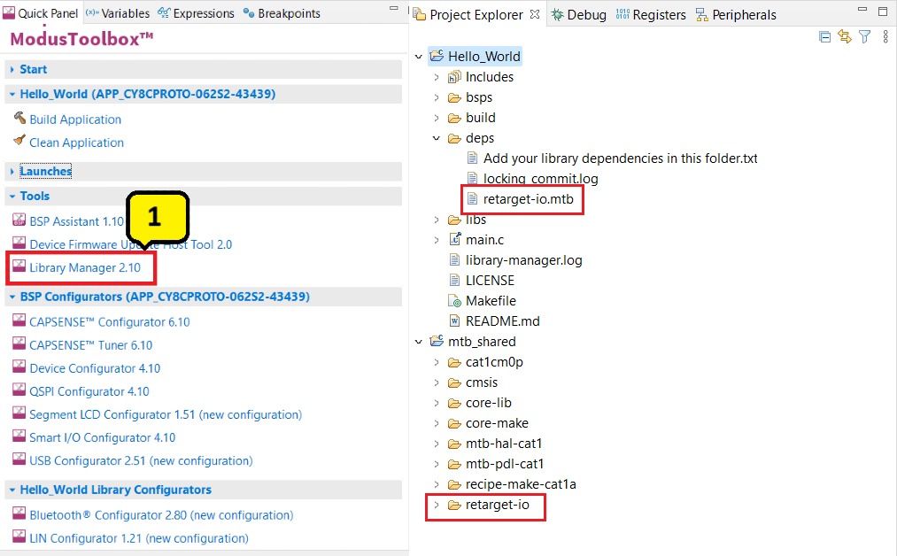
The files necessary to use the
retarget-io
middleware are added in the
mtb_shared > retarget_io
folder, and the
.mtb
file is added to the
deps
folder, as shown in the following figure.
Figure 11. Add the retarget-io middleware
Configuration of UART, timer peripherals, pins, and system clocks
The configuration of the debug UART peripheral, timer peripheral, pins, and system clocks can be done directly in the code using the function APIs provided by the BSP and HAL. Therefore, it is not necessary to configure them with the Device Configurator. See
Write firmware
section for more details.
Write firmware
At this point in the development process, you have created an application with the assistance of an application template and modified it to add the
retarget-io
middleware. In this section, you will write the firmware that implements the design functionality.
If you are working from scratch using the
Empty
PSOC™ 6
starter application,
you can copy the respective source code to the
main.c
file of the application project from the code snippet provided in this section.
If you are using the
Hello World
code example, all the required files are already in the application.
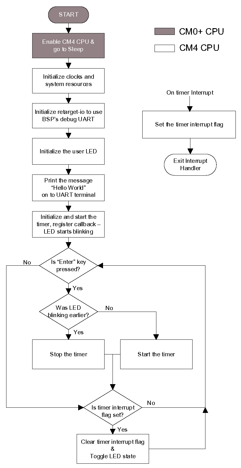
Firmware flow
Examine the code in the
main.c
file of the application.
Figure 12
shows the firmware flowchart.
The CM0+ core comes out of reset and enables the CM4 core. The CM0+ core is then configured to go to sleep by the provided CM0+ application. Resource initialization for this example is performed by the CM4 core. It configures the system clocks, pins, clock to peripheral connections, and other platform resources.
When the CM4 core is enabled, the clocks and system resources are initialized by the BSP initialization function. The
retarget-io
middleware is configured to use the debug UART, and the user LED is initialized. The debug UART prints a “Hello World!” message on the terminal emulator – the on-board KitProg3 acts the USB-UART bridge to create the virtual COM port. A timer object is configured to generate an interrupt every 1000 milliseconds. At each Timer interrupt, the CM4 core toggles the LED state on the kit.
The firmware is designed to accept the 'Enter' key as an input, and on every press of the 'Enter' key, the firmware starts or stops the blinking of the LED.
Note that this application code uses BSP/HAL/middleware functions to execute the intended functionality.
cybsp_init()
– This BSP function
sets up the HAL hardware manager and
initializes all the system resources of the device, including but not limited to the system clocks and power regulators.
cy_retarget_io_init()
– This
function from the
retarget-io
middleware uses the aliases set up in the
BSP for the debug UART pins to configure the debug UART with a standard baud rate of
115200 and also redirects the input/output stream to the debug UART.
Note: You can open the Device Configurator to view the aliases that are set up in the BSP.
cyhal_gpio_init()
– This function from the GPIO HAL initializes the physical pin to drive the LED. The LED used is derived from the alias for the pin set up in the BSP.
timer_init()
– This function wraps a set of timer
HAL
function calls to instantiate and configure a hardware timer. It also sets up a callback for the timer interrupt.
Copy the following code snippet to the
main.c
file of your application project.
Code listing 1:
main.c
file
#include "cyhal.h"
#include "cybsp.h"
#include "cy_retarget_io.h"


/*******************************************************************************
* Macros
*******************************************************************************/

/* LED blink timer clock value in Hz  */
#define LED_BLINK_TIMER_CLOCK_HZ          (10000)

/* LED blink timer period value */
#define LED_BLINK_TIMER_PERIOD            (9999)


/*******************************************************************************
* Function Prototypes
*******************************************************************************/
void timer_init(void);
static void isr_timer(void *callback_arg, cyhal_timer_event_t event);


/*******************************************************************************
* Global Variables
*******************************************************************************/
bool timer_interrupt_flag = false;
bool led_blink_active_flag = true;

/* Variable for storing character read from terminal */
uint8_t uart_read_value;

/* Timer object used for blinking the LED */
cyhal_timer_t led_blink_timer;


/*******************************************************************************
* Function Name: main
********************************************************************************
* Summary:
* This is the main functionfor CM4 core. It sets up a timer to trigger a
* periodic interrupt. The main while loop checks for the status of a flag set
* by the interrupt and toggles an LED at 1Hz to create an LED blinky. The
* while loop also checks whether the 'Enter' key was pressed and
* stops/restarts LED blinking.
*
* Parameters:
*  none
*
* Return:
*  int
*
*******************************************************************************/
int main(void)
{
    cy_rslt_t result;

    /* Initialize the device and board peripherals */
    result = cybsp_init();

    /* Board init failed. Stop program execution */
    if (result != CY_RSLT_SUCCESS)
    {
        CY_ASSERT(0);
    }

    /* Enable global interrupts */
    __enable_irq();

    /* Initialize retarget-io to use the debug UART port */
    result = cy_retarget_io_init(CYBSP_DEBUG_UART_TX, CYBSP_DEBUG_UART_RX,
                                 CY_RETARGET_IO_BAUDRATE);

    /* retarget-io init failed. Stop program execution */
    if (result != CY_RSLT_SUCCESS)
    {
        CY_ASSERT(0);
    }

    /* Initialize the User LED */
    result = cyhal_gpio_init(CYBSP_USER_LED, CYHAL_GPIO_DIR_OUTPUT,
                             CYHAL_GPIO_DRIVE_STRONG, CYBSP_LED_STATE_OFF);

    /* GPIO init failed. Stop program execution */
    if (result != CY_RSLT_SUCCESS)
    {
        CY_ASSERT(0);
    }

    /* \x1b[2J\x1b[;H - ANSI ESC sequence for clear screen */
    printf("\x1b[2J\x1b[;H");

    printf("****************** "
           "Hello World! Example "
           "****************** \r\n\n");

    printf("Hello World!!!\r\n\n");

    printf("For more projects, "
           "visit our code examples repositories:\r\n\n");

    printf("https://github.com/Infineon/"
           "Code-Examples-for-ModusToolbox-Software\r\n\n");

    /* Initialize timer to toggle the LED */
    timer_init();

    printf("Press 'Enter' key to pause or "
           "resume blinking the user LED \r\n\r\n");

    for (;;)
    {
        /* Check if 'Enter' key was pressed */
        if (cyhal_uart_getc(&cy_retarget_io_uart_obj, &uart_read_value, 1)
             == CY_RSLT_SUCCESS)
        {
            if (uart_read_value == '\r')
            {
                /* Pause LED blinking by stopping the timer */
                if (led_blink_active_flag)
                {
                    cyhal_timer_stop(&led_blink_timer);

                    printf("LED blinking paused \r\n");
                }
                else /* Resume LED blinking by starting the timer */
                {
                    cyhal_timer_start(&led_blink_timer);

                    printf("LED blinking resumed\r\n");
                }

                /* Move cursor to previous line */
                printf("\x1b[1F");

                led_blink_active_flag ^= 1;
            }
        }

        /* Check if timer elapsed (interrupt fired) and toggle the LED */
        if (timer_interrupt_flag)
        {
            /* Clear the flag */
            timer_interrupt_flag = false;

            /* Invert the USER LED state */
            cyhal_gpio_toggle(CYBSP_USER_LED);
        }
    }
}


/*******************************************************************************
* Function Name: timer_init
********************************************************************************
* Summary:
* This function creates and configures a Timer object. The timer ticks
* continuously and produces a periodic interrupt on every terminal count
* event. The period is defined by the 'period' and 'compare_value' of the
* timer configuration structure 'led_blink_timer_cfg'. Without any changes,
* this application is designed to produce an interrupt every 1 second.
*
* Parameters:
*  none
*
*******************************************************************************/
 void timer_init(void)
 {
    cy_rslt_t result;

    const cyhal_timer_cfg_t led_blink_timer_cfg =
    {
        .compare_value = 0,                 /* Timer compare value, not used */
        .period = LED_BLINK_TIMER_PERIOD,   /* Defines the timer period */
        .direction = CYHAL_TIMER_DIR_UP,    /* Timer counts up */
        .is_compare = false,                /* Don't use compare mode */
        .is_continuous = true,              /* Run timer indefinitely */
        .value = 0                          /* Initial value of counter */
    };

    /* Initialize the timer object. Does not use input pin ('pin' is NC) and
     * does not use a pre-configured clock source ('clk' is NULL). */
    result = cyhal_timer_init(&led_blink_timer, NC, NULL);

    /* timer init failed. Stop program execution */
    if (result != CY_RSLT_SUCCESS)
    {
        CY_ASSERT(0);
    }

    /* Configure timer period and operation mode such as count direction,
       duration */
    cyhal_timer_configure(&led_blink_timer, &led_blink_timer_cfg);

    /* Set the frequency of timer's clock source */
    cyhal_timer_set_frequency(&led_blink_timer, LED_BLINK_TIMER_CLOCK_HZ);

    /* Assign the ISR to execute on timer interrupt */
    cyhal_timer_register_callback(&led_blink_timer, isr_timer, NULL);

    /* Set the event on which timer interrupt occurs and enable it */
    cyhal_timer_enable_event(&led_blink_timer, CYHAL_TIMER_IRQ_TERMINAL_COUNT,
                              7, true);

    /* Start the timer with the configured settings */
    cyhal_timer_start(&led_blink_timer);
 }


/*******************************************************************************
* Function Name: isr_timer
********************************************************************************
* Summary:
* This is the interrupt handler function for the timer interrupt.
*
* Parameters:
*    callback_arg    Arguments passed to the interrupt callback
*    event            Timer/counter interrupt triggers
*
*******************************************************************************/
static void isr_timer(void *callback_arg, cyhal_timer_event_t event)
{
    (void) callback_arg;
    (void) event;

    /* Set the interrupt flag and process it from the main while(1) loop */
    timer_interrupt_flag = true;
}
Figure 12. Firmware flowchart
This completes the summary of how the firmware works in the code example. Feel free to explore the source files for a deeper understanding.
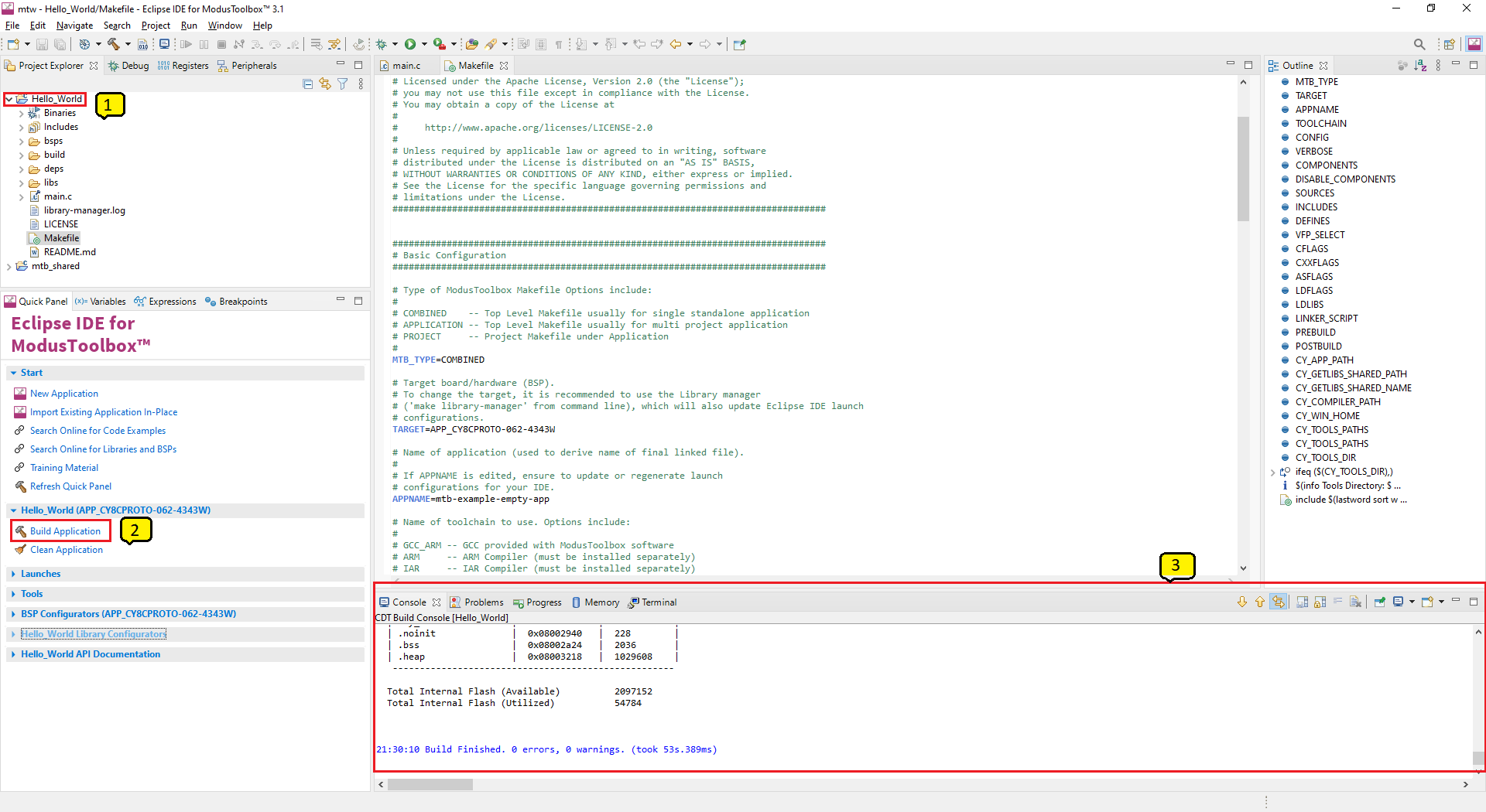
Build the application
This section shows how to build the application.
Select the application project in the Project Explorer view.
Click Build Application shortcut under the <name> group in the Quick Panel .
It selects the build configuration from the Makefile and compiles/links all projects that constitute the application. By default, Debug configurations are selected.
The Console view lists the results of the build operation, as Figure 13 shows.
Figure 13. Build the application
If you encounter errors, revisit earlier steps to ensure that you completed all the required tasks.
Note: You can also use the command-line interface (CLI) to build the application. See the Build system section in the ModusToolbox™ tools package user guide . This document is located in the /docs_<version>/ folder in the ModusToolbox™ installation.
Program the device
This section shows how to program the PSOC™ 6 .
ModusToolbox™ software
uses the OpenOCD protocol to program and debug applications on PSOC™ 6 s
. The kit must be running KitProg3. Some kits are shipped with KitProg2 firmware instead of KitProg3. See Debugging the application using KitProg3/MiniProg4 for details. The ModusToolbox™ tools package includes the
fw-loader
command-line tool to switch the KitProg firmware from KitProg2 to KitProg3. See the PSOC™ 6 KitProg Firmware Loader section in the Eclipse IDE for ModusToolbox™ user guide for more details.
If you are using a development kit with a built-in programmer connect the board to your computer using the USB cable.
If you are developing on your own hardware, you can use a hardware programmer/debugger; for example, a
, https://www.segger.com/products/debug-probes/j-link/ , or https://www2.keil.com/mdk5/ulink/ulinkpro/ .
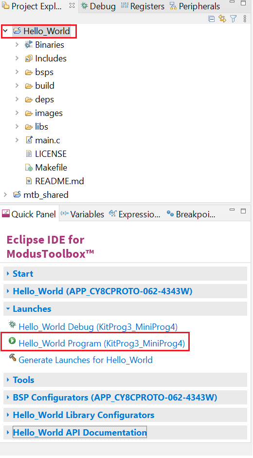
Select the application project and click the <application name> Program (KitProg3_MiniProg4) shortcut under the Launches group in the Quick Panel , as Figure 14 shows. The IDE will select and run the appropriate run configuration.
Note: This step also performs a build if any files have been modified since the last build.
Figure 14. Programming an application to a device
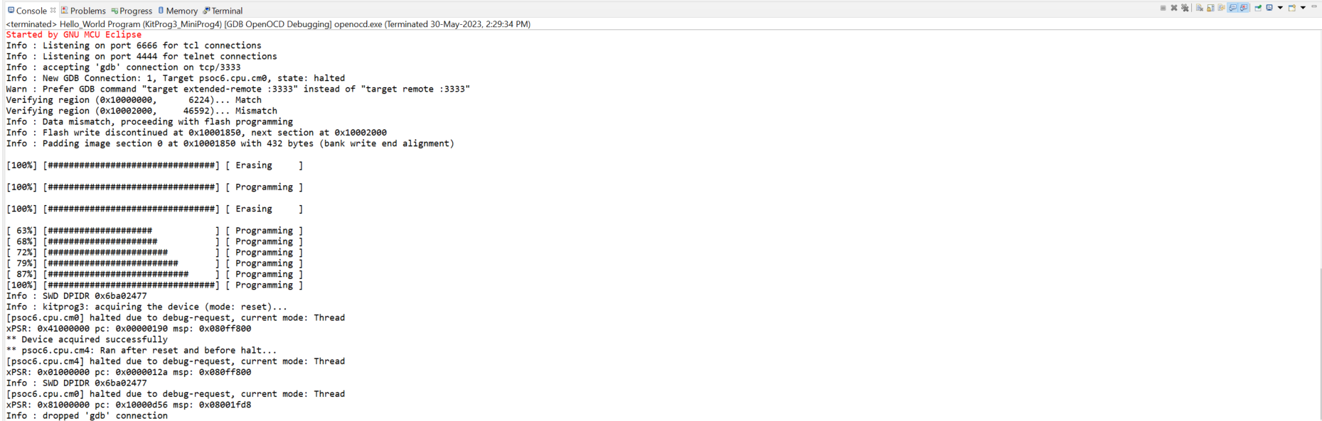
The
Console
view lists the results of the programming operation, as shown in the following figure.
Figure 15. Programming an application to a device
Test your design
This section describes how to test your design.
Follow these steps to observe the output of your design. This note uses Tera Term as the UART terminal emulator to view the results, but you can use any terminal of your choice to view the output.
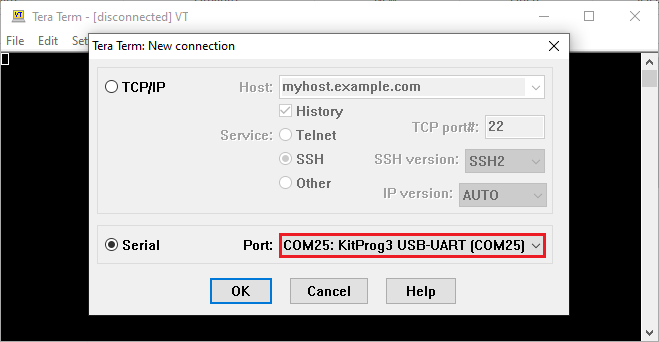
Select the serial port
Launch Tera Term and select the USB-UART COM port as Figure 16 shows. Note that your COM port number may be different.
Figure 16. Selecting the KitProg3 COM port in Tera Term
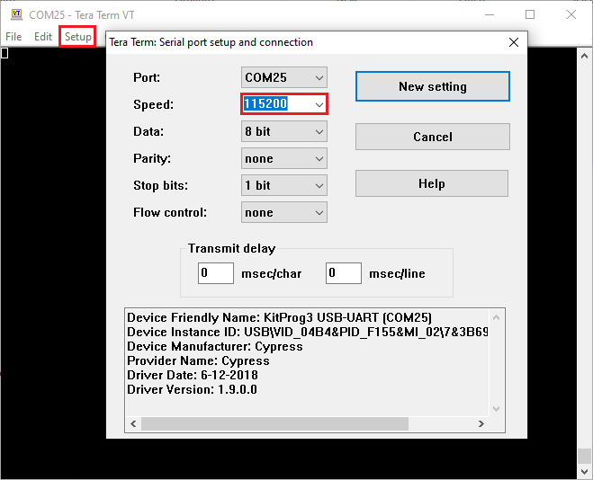
Set the baud rate
Set the baud rate to 115200 under
Setup > Serial port
as Figure 17 shows.
Figure 17. Configuring the baud rate in Tera Term
Reset the device
Press the reset switch (
SW1
) on the kit.
A message appears on the terminal as
Figure 18
shows
. The user LED on the kit will start blinking.
Figure 18. Printed UART message

Pause/resume LED blinking functionality
Press the
Enter
key to pause/resume blinking the LED. When the LED blinking is paused, a corresponding message will be displayed on the terminal as shown in
Figure 19
.
Figure 19. Printed UART message

Debugging the application using KitProg3/MiniProg4
All PSOC™ 6 kits have a KitProg3 on-board programmer/debugger. It supports Cortex® Microcontroller Software Interface Standard - Debug Access Port (CMSIS-DAP). See the
KitProg3 user guide
for details. The Eclipse IDE requires KitProg3 and uses the OpenOCD protocol for debugging PSOC™ 6 MCU applications.
Note: The PSOC™ 6 Wi-Fi-Bluetooth® pioneer kit(CY8CKIT-062-WiFi-BT) and PSOC™ 6 Bluetooth® LE pioneer kit(CY8CKIT-062-BLE) have the KitProg2 onboard programmer/debugger firmware pre-installed. To work with ModusToolbox™, upgrade the firmware to KitProg3 using the fw-loader command-line tool included in the ModusToolbox™ software. Refer to the "PSOC™ 6 Programming/Debugging - KitProg Firmware Loader" section in the Eclipse IDE for ModusToolbox™ user guide for more details.
The Eclipse IDE contains several launch configurations that control various settings for programming the devices and launching the debugger. Depending on the kit and the type of applications you are using, there are various launch configurations available. One such configuration is the KitProg3/MiniProg4 launch configuration. Refer to the "PSOC™ MCU programming/debugging" section in the
Eclipse IDE for ModusToolbox™ user guide
for more details on the launch configurations.
When an application is created, the tool generates the launch configurations for KitProg3_MiniProg4 under
Launches
in the
Quick Panel
, as shown in the following figure.
Figure 20. KitProg3/MiniProg4 launch configuration
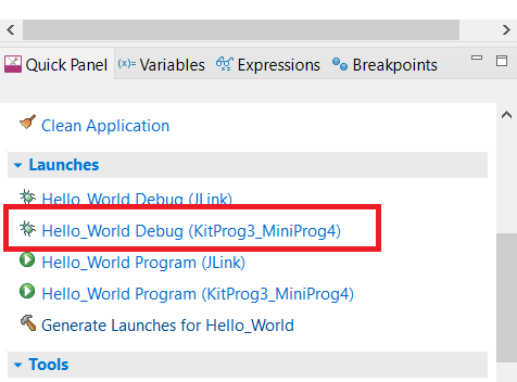
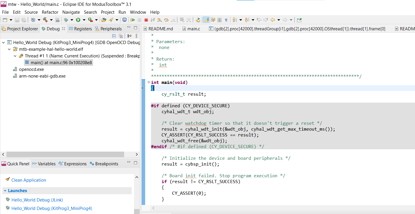
Connect the device to the host machine and click on the
Hello_World Debug (KitProg3_MiniProg4)
launch to start debugging, as shown in
Figure 20
. Once the debugging starts, the execution halts at the main() function, and the user can start debugging from the start of main(), as shown in the following figure.
Figure 21. Debug main()
Visual Studio Code (VS Code) for ModusToolbox™
Refer to the
Visual Studio Code for ModusToolbox™ user guide
for creating a new application on VS Code.
IAR Embedded Workbench for ModusToolbox™
Refer to the
IAR Embedded Workbench for ModusToolbox™ user guide
for creating a new application on IAR.
Keil µVision for ModusToolbox™
Refer to the
Keil µVision for ModusToolbox™ user guide
for creating a new application on Keil uVision.
Summary
This application note explored the
PSOC™ 6
device architecture and the associated development tools.
PSOC™ 6
is a truly programmable embedded system-on-chip with configurable analog and digital peripheral functions, memory, and a dual-core system on a single chip. The integrated features, embedded security, and low-power modes make
PSOC™ 6
an ideal choice for smart home, IoT gateways, and other related applications.
References
For a complete and updated list of
PSOC™ 6
code examples, please visit our
GitHub
. For more
PSOC™ 6
-related documents, please visit our
PSOC™ 6
Digital Documentation Portal
.
lists the system-level and general application notes that are recommended for the next steps in learning about
PSOC™ 6
and ModusToolbox™.
Document | Document name |
|---|---|
PSOC™ 6 hardware design considerations |
Table 3 lists the application notes (AN) for specific peripherals and applications.
Document | Document name |
|---|---|
System resources, CPU, and interrupts | |
AN215656 | PSOC™ 6 dual-core system design |
AN217666 | PSOC™ 6 interrupts |
AN235279 | Performing ETM and ITM Trace on PSOC™ 6 |
CAPSENSE™ | |
AN92239 | Proximity sensing with CAPSENSE™ |
AN85951 | PSOC™ 4 and PSOC™ 6 CAPSENSE™ design guide |
Device Firmware Update | |
PSOC™ 6 device firmware update software development kit guide | |
Low-power | |
PSOC™ 6 low-power analog | |
PSOC™ 6 low-power modes and power reduction techniques | |
Security | |
PSOC™ 6 MCU designing a custom secured system | |
AN227860 | PSOC™ 64 Secure MCU Secure Boot SDK User Guide |
AN239061 | PSOC™ 64 security getting started guide |
ModusToolbox™ | |
Glossary
This section lists the most commonly used terms that you might encounter while working with PSOC™ family of devices.
Board support package (BSP) : A BSP is the layer of firmware containing board-specific drivers and other functions. The board support package is a set of libraries that provide firmware APIs to initialize the board and provide access to board level peripherals.
Cypress Programmer : Cypress Programmer is a flexible, cross-platform application for programming Cypress devices. It can Program, Erase, Verify, and Read the flash of the target device.
Hardware abstraction layer (HAL) : The HAL wraps the lower level drivers (like MTB-PDL-CAT1 ) and provides a high-level interface to the MCU. The interface is abstracted to work on any MCU.
KitProg: The KitProg is an onboard programmer/debugger with USB-I2C and USB-UART bridge functionality. The KitProg is integrated onto most PSOC™ development kits.
MiniProg3 / MiniProg4 : Programming hardware for development that is used to program PSOC™ devices on your custom board or PSOC™ development kits that do not support a built-in programmer.
Personality: A personality expresses the configurability of a resource for a functionality. For example, the SCB resource can be configured to be an UART, SPI or I2C personalities.
PSOC™ : A programmable, embedded design platform that includes a CPU, such as the 32-bit Arm® Cortex®-M0, with both analog and digital programmable blocks. It accelerates embedded system design with reliable, easy-to-use solutions, such as touch sensing, and enables low-power designs.
Middleware : Middleware is a set of firmware modules that provide specific capabilities to an application. Some middleware may provide network protocols (e.g. MQTT), and some may provide high level software interfaces to device features (e.g. USB, audio).
ModusToolbox™ : An Eclipse based embedded design platform for IoT designers that provides a single, coherent, and familiar design experience combining the industry's most deployed Wi-Fi and Bluetooth® technologies, and the lowest power, most flexible MCUs with best-in-class sensing.
Peripheral driver library (PDL) : The peripheral driver library (PDL) simplifies software development for the PSOC™ 6 architecture. The PDL reduces the need to understand register usage and bit structures, thus easing software development for the extensive set of peripherals available.
Revision history
Document version | Date of release | Description of changes |
|---|---|---|
** | 2017-07-26 | New application note |
*A | 2018-01-09 | Updated screenshots with latest release of ModusToolbox™ Added new supported PSOC™ 6 devices Added AnyCloud description under ModusToolbox™ software |
*B | 2019-04-16 | Added new supported PSOC™ 6 device – PSOC™ 62S4 Added information on PSOC™ 6 product lines and development kits available for each product line |
*C | 2020-05-06 | Updated Figure 2 Updated Screenshots with MTB v2.2 Added mtb_shared folder description, updated application creation process with MTB flow |
*D | 2021-03-11 | Updated to Infineon template |
*E | 2021-07-09 | Updated the GitHub links Added reference to new PSOC™ 6 low-power analog Updated Figure 16 to Figure 19 Firmware updated to the latest version |
*F | 2022-07-21 | Template update |
*G | 2022-09-12 | Updated the development flow as per MTB v3.0 software Updated link references Updated configurator info Added new Figure 2 and Figure 7 Updated Figure 8 and Figure 14 Added reference to new AN235279 Added a new section for ModusToolbox™ Applications Removed reference to deprecated AN225588 Updated Figure 17 to Figure 19 |
*H | 2023-06-09 | Updated content with latest release of ModusToolbox™ 3.1 |
*I | 2023-12-04 | Updated with kit CY8CPROTO-062S2-43439 |
*J | 2024-03-22 | Added references to all the supporting IDEs on ModusToolbox™ and restructured the content |
*K | 2025-05-30 | Updated links in sections Visual Studio Code (VS Code) for ModusToolbox™ , IAR Embedded Workbench for ModusToolbox™ , and Keil µVision for ModusToolbox™ |
Trademarks
The Bluetooth® word mark and logos are registered trademarks owned by Bluetooth SIG, Inc., and any use of such marks by Infineon is under license.
PSOC™, formerly known as PSoC™, is a trademark of Infineon Technologies. Any references to PSoC™ in this document or others shall be deemed to refer to PSOC™.