AN235297 Creating a ModusToolbox™ 3.x BSP
About this document
Scope and purpose
This application note describes how to create a Board Support Package (BSP) using the ModusToolbox™ BSP Assistant tool. This document explains the basics of a BSP along with the various use cases where the BSP Assistant tool can be useful during application development using ModusToolbox™ version 3.1 or above.
Intended audience
This document is intended for anyone who needs to create a user-specific design board using an Infineon device supported inside the ModusToolbox™ ecosystem.
Document conventions
| Convention | Explanation |
|---|---|
| Bold | Emphasizes heading levels, column headings, menus and sub-menus. |
| Italics | Denotes file names and paths. |
| Courier New | Denotes APIs, functions, interrupt handlers, events, data types, error handlers, file names, directories, command line inputs, code snippets, etc. |
| File > New | Indicates that a cascading sub-menu opens when you select a menu item. |
Abbreviations and definitions
| Abbreviation | Meaning |
|---|---|
| BSP | Board support package |
| MCU | Microcontroller unit |
| MPN | Manufacturer part number |
Introduction
What is a BSP?
BSPs are a set of files and directories that provide the necessary functionality to develop target applications on any given board. The board is typically a printed circuit board (PCB) used in any electronics product like a mobile phone, laptop, digital camera, etc. These boards usually have a microcontroller (or microprocessor) chip with various peripherals and other components that are wired together to meet the target application requirements.
Infineon has a range of microcontroller devices belonging to various families such as PSoC™ 4, PSoC™ 6, and XMC™, and provides development kits (or boards) for the evaluation of these devices. The BSPs for these development boards are made available through the ModusToolbox™ ecosystem in the Infineon GitHub website.
BSP Assistant overview
The BSP Assistant tool helps you create and manage custom BSPs for the board designed for your application using Infineon MCUs. The tool is available in both graphical user interface (GUI) and command line interface (CLI) versions.
Overview
This application note has the following sections to help you learn the following:
- BSP design - Explains the BSP architecture
- Using the BSP Assistant tool - Explains typical BSP Assistant tool use cases such as creating and modifying BSPs using the Hello World code example
- Advanced usage - Explains advanced BSP Assistant tool use cases like BSP migration between generations
Software requirement
| Software | Minimum required version |
|---|---|
ModusToolbox™ | 3.1 |
BSP design
As mentioned previously, a BSP is a set of files and directories with content specific to a target board that enables you to develop a target application. BSPs for evaluation boards of MCUs supported by ModusToolbox™ are made available through the ModusToolbox™ ecosystem via Infineon GitHub repositories.
Software
Software is provided in source or library form and contains a set of APIs to control and configure the microcontroller and other onboard components. A BSP specifies software that it requires as dependencies. For Infineon BSPs provided on GitHub, dependencies are specified in a manifest file. Once a BSP is created by the user, (either during application creation or by using the BSP Assistant) the dependencies are specified in a set of *.mtbx files in the BSP's deps subdirectory. These dependency files contain information for downloading the minimum set of libraries required to develop an application on the given board.
Peripheral Driver Library (PDL)
PDL contains a set of low-level APIs to control hardware peripherals such as UART and SPI. The interfaces are usually specific to a particular microcontroller or microcontroller family. For some MCU families, the low-level API library may use an alternative name for the low-level library APIs other than PDL mentioned in this section.
Hardware Abstraction Layer (HAL)
HAL contains a set of high-level APIs to control hardware peripherals; the interfaces are more portable than PDL in case of the following changes:
- Changing the pin assignments for the peripherals within the same microcontroller
- Porting to another microcontroller within the same family
- Porting to another microcontroller in a different family
Other libraries
These libraries provide the following functionality:
- Abstraction libraries: These typically abstract the RTOS to help in porting the application across different RTOS like FreeRTOS or to a different board.
- Base libraries: These libraries, such as core-lib, core-make, recipe-make are necessary for the build process.
- Board utilities libraries: These are libraries supporting various utilities available on the board other than the microcontroller, such as sensors and displays, and are used to control them.
- MCU Middleware: These include middleware that provides RTOS services, such as FreeRTOS, or peripheral services, such as capacitive sensing.
Documentation
BSPs have the following documentation accompanying them:
- Docs/api_reference_manual.html: Provides details of the APIs, structures, and macros that are provided as part of the BSP and details of the board design, including the available microcontroller, LEDs, buttons, memory, and sensors.
- README.md: Provides top-level information about the BSP and usually contains links to additional documentation.
- RELEASE.md: Provides information about various versions of the BSP and changes from one version to another.
Typical BSP contents
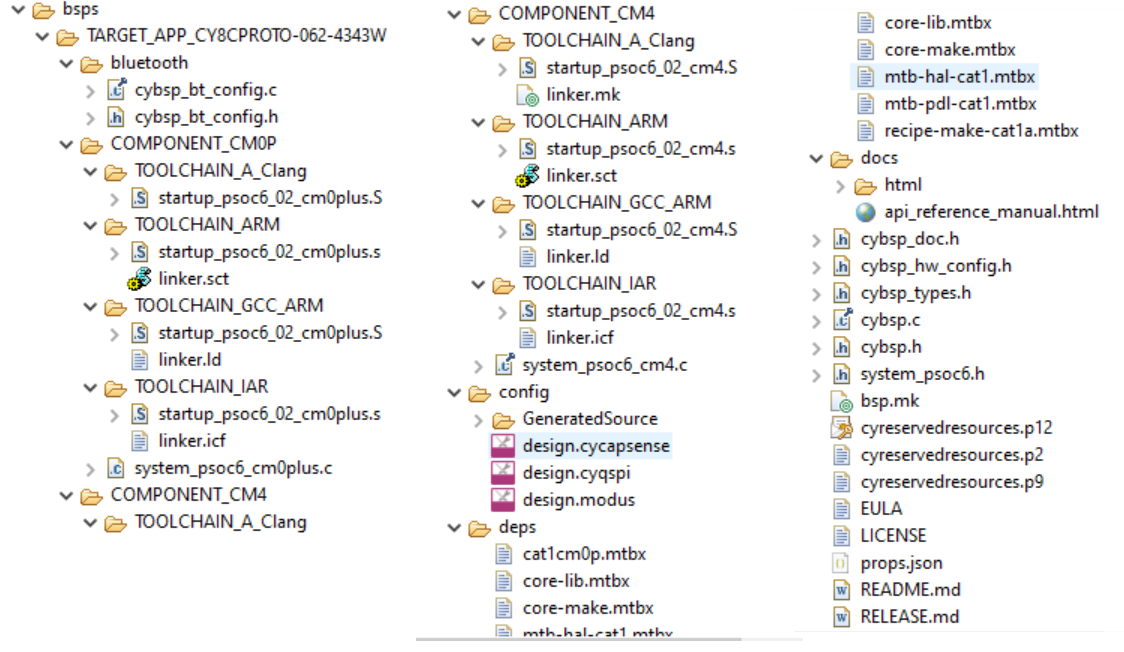
Startup code and linker files
Startup code is usually in assembly format and is the code that executes after a CPU reset. These are usually specific to a CPU and configure various microcontroller special-function registers such as the stack pointer.
Linker files are used to map various sections of the compiled source code into memory regions like flash and SRAM. These are used by the build system to generate the final binary that is programmed onto the target.
Both startup code and linker files are specific to a build environment like GCC. BSPs that accompany the ModusToolbox™ ecosystem provides these items for the GCC, IAR, and Arm® build environments.
Since the startup code and linker files are CPU
and toolchain dependent, they are located inside COMPONENT and
TOOLCHAIN directories inside the BSP, which allows them to be
included conditionally. For example, the directory
COMPONENT_CM4/TOOLCHAIN_GCC_ARM would contain startup
code and linker script files that are only used when
building a project for the CM4 CPU with the GCC_ARM toolchain.
Configuration files
ModusToolbox™ comes with various BSP configurator tools that enable you to configure the microcontroller peripherals. Typically, these configure the clock, pin, and other resource-related settings in the microcontroller. There are GUI tools like the Device Configurator to open/edit the configuration files, which are saved in XML format with a specific file extension like design.modus. When the configuration is saved, the tool generates the configuration code that is linked together with the application code during the build process.
The files for each BSP configurator are located in the config directory inside the BSP.
The following table summarizes the available BSP configurator tools, associated configuration file, and a brief description.
| Configurator tool name | Configuration file extension | Description |
|---|---|---|
capsense-configurator | *.cycapsense | CAPSENSE™ Configurator is used to create and configure CAPSENSE™ widgets, and generate code to control the application firmware. |
device-configurator | *.modus | Device Configurator is used to enable and configure device peripherals, such as clocks and pins, as well as standard MCU peripherals that do not require their own tool. |
qspi-configurator | *.cyqspi *.cymem | The QSPI Configurator is used to open or create configuration files, configure memory slots, and generate code for your application when external flash devices are connected to the MCU using a Quad Serial Peripheral Interface (QSPI). |
seglcd-configurator | *.cyseglcd | SegLCD Configurator is used to generate display structures for the SegLCD Driver. |
smartio-configurator | *.modus | Smart I/O Configurator is used to configure the smart I/O pins in the MCU. |
| usbdev-configurator | *.cyusbdev | Universal Serial Bus(USB) configurator is used to configure USB device descriptors. |
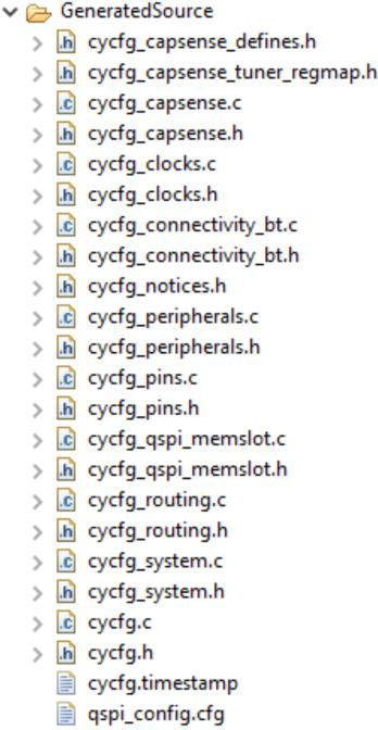
Generated source files
BSP Configurators generate related source/header files in the GeneratedSource subdirectory that are then included as part of the application build. This helps avoid writing lengthy configuration code.
Static source files
A BSP contains static source files with initialization routines for the board. These must be called by the application code before using any MCU peripherals. Typical BSP static source files that are included with ModusToolbox™ BSPs are as follows:
- cybsp.c - Provides initialization code for starting up the hardware contained on the Infineon board
- cybsp.h - API header file for cybsp.c
- cybsp_doc.h - Contains code for generating BSP html documentation
- cybsp_types.h - Contains code for the states of button/pin/led on the Infineon board
- bluetooth/cybsp_bt_config.c - Provides initialization settings for the Bluetooth® module
- bluetooth/cybsp_bt_config.h - API header file for cybsp_bt_config.c
Documentation files
A BSP contains Doxygen/markup-based documentation for the application developer with the details of various libraries, release notes, etc.
Using the BSP Assistant tool
This section describes two basic use cases for working with the BSP Assistant tool:
These use cases show the tools in a Windows operating system, as well as using the Eclipse IDE. If you use another IDE/OS combination, the steps will be similar but may not be identical.
Creating a new BSP
Use this workflow to create a new BSP for the Infineon MCU board. You can create the BSP using an existing BSP as a starting point and then modify it for your needs, or you can create a BSP from scratch based on the devices the board contains. For demonstration, this workflow considers creating a BSP for a board based on the CY8C6347BZI-BLD44 MCU device. Each method is described in the following sections.
Create and configure the BSP using the existing sample board
Type bsp-assistant in the Windows search tool to open the BSP Assistant tool or look in the Window's menu under "ModusToolbox <version>".
After the tool loads, select to open the Create New BSP From Sample Board window.
Figure 4. Create New BSP dialog 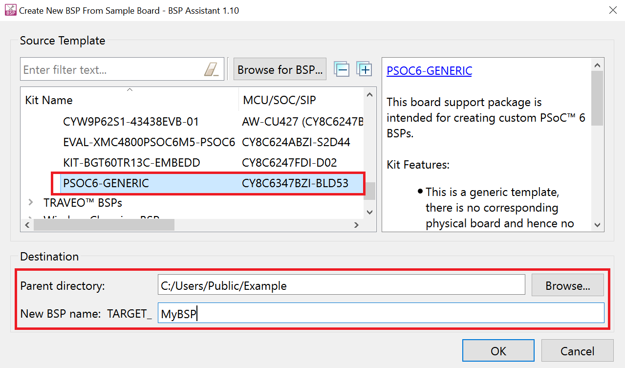
Select PSOC6-GENERIC under the PSoC™ 6 BSPs category or if the board you are creating is similar to an existing Infineon board, you can select it as the starting BSP.
Set the directory path where the BSP will be created in the Parent Directory text box.
Type a suitable name for the BSP in the New BSP name: TARGET_ text box. This example uses the name MyBSP.
Click OK.
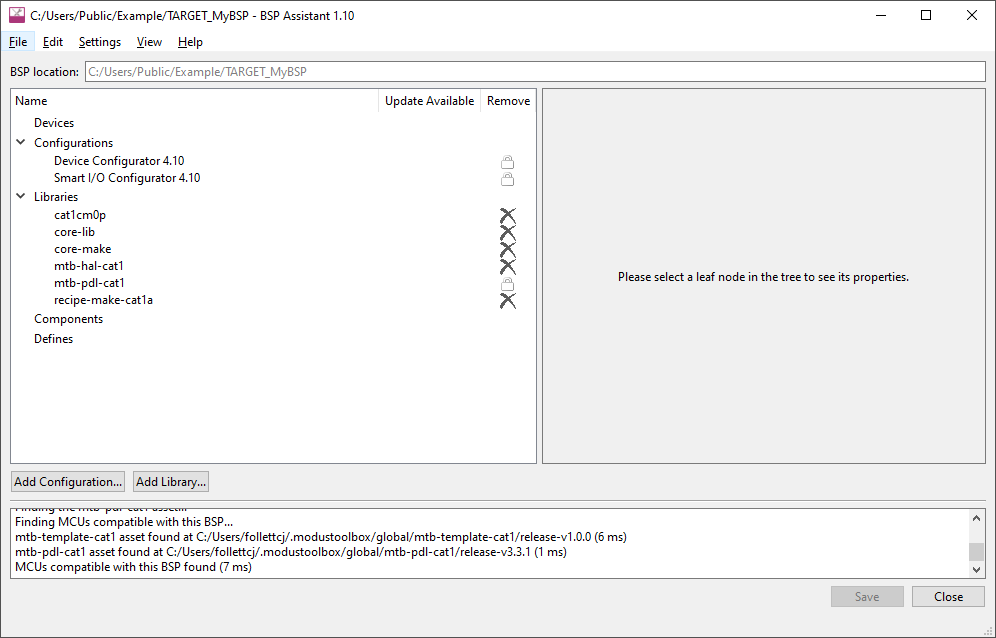
The BSP Assistant tool starts downloading the contents from the Infineon GitHub website; when finished, the screen should look like the following:
Figure 5. BSP Assistant finished loading content 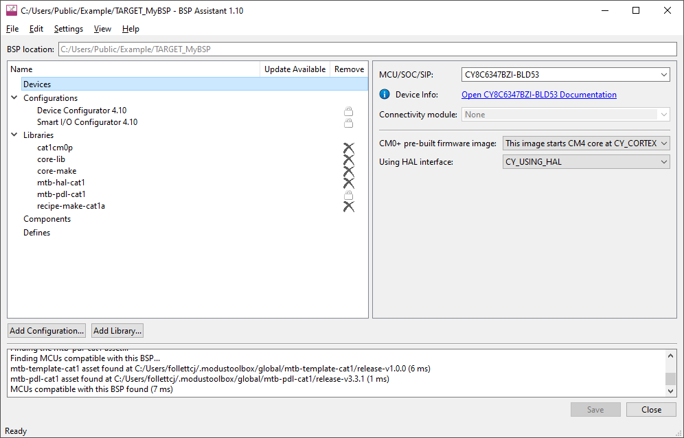
Change the MCU device to CY8C6347BZI-BLD44 by selecting it from the MCU/SOC/SIP drop-down menu under the Devices section as shown and click Save.
Note: You can start typing the MCU name in the drop-down box to filter the choices.Figure 6. Changing MCU device 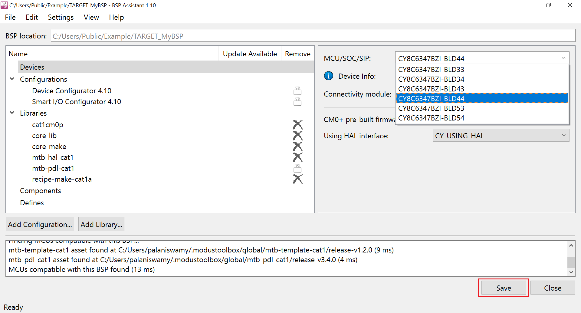
Messages appear in the output console ending with Saving changes to BSP succeeded. as follows:
Figure 7. Output console messages 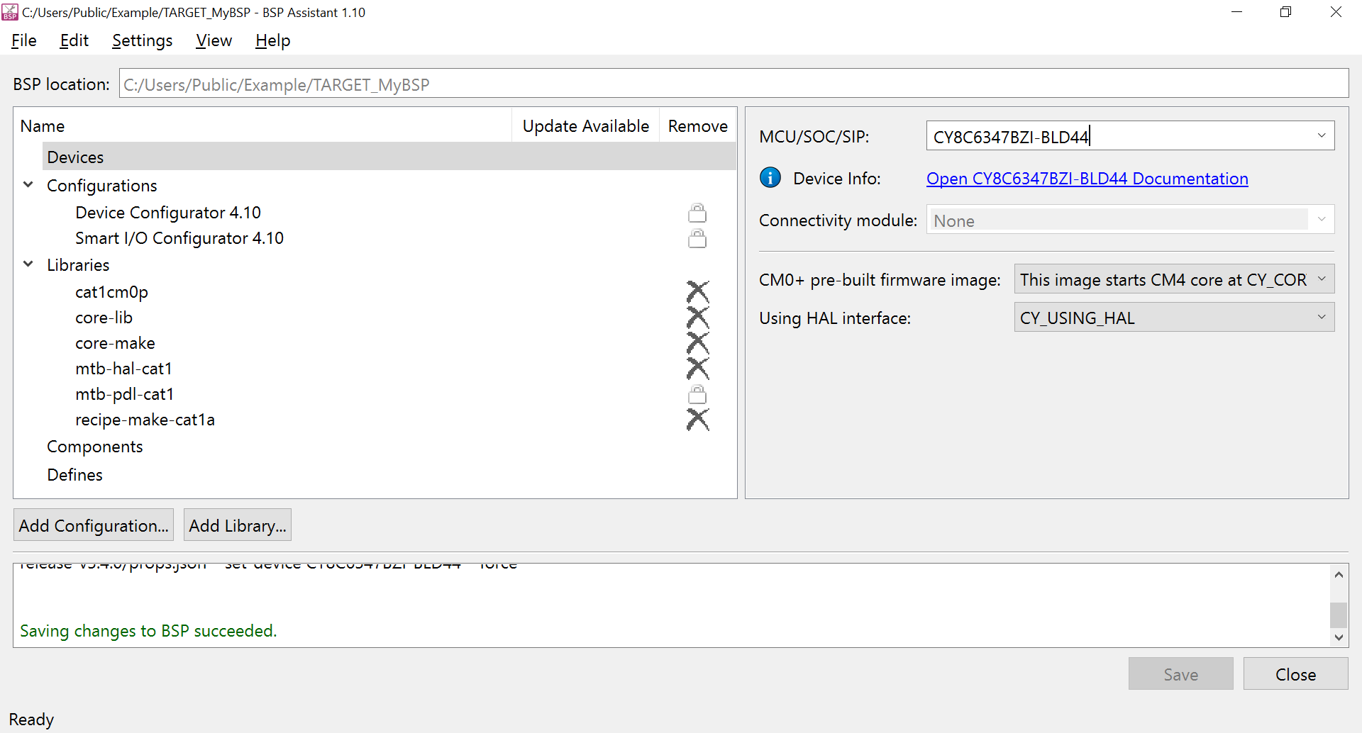
Under the Configurations section, click Device Configurator 4.10, and then click the Edit Configuration button to open the Device Configurator tool.
Figure 8. Opening Configurator from BSP Assistant 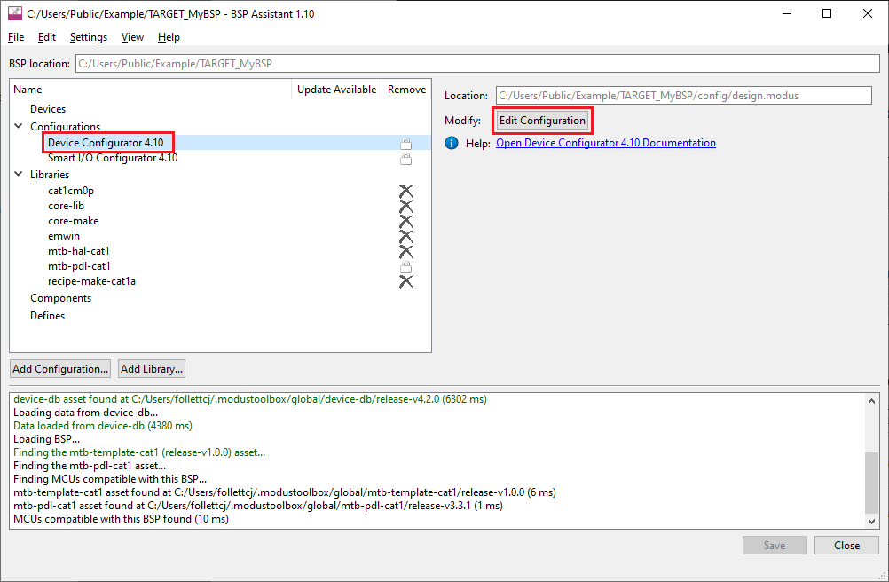
For this demo, make the following changes:
- Name the pin P5[0] as CYBSP_DEBUG_UART_RX from the Pins tab.
- Name the pin P5[1] as CYBSP_DEBUG_UART_TX from the Pins tab.
- Name the pin P13[7] as CYBSP_USER_LED from the Pins tab.
- Disable
CLK_ALT_SYS_TICKfrom the System tab, .
Figure 9. Changing pin settings 1 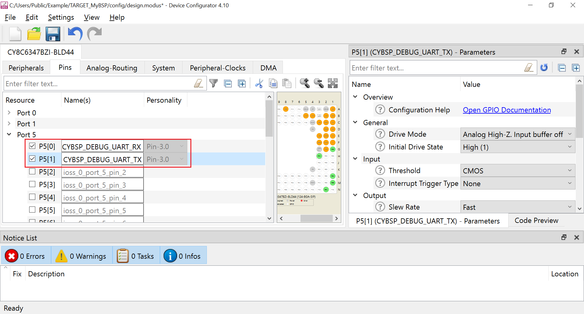
Figure 10. Changing pin settings 2 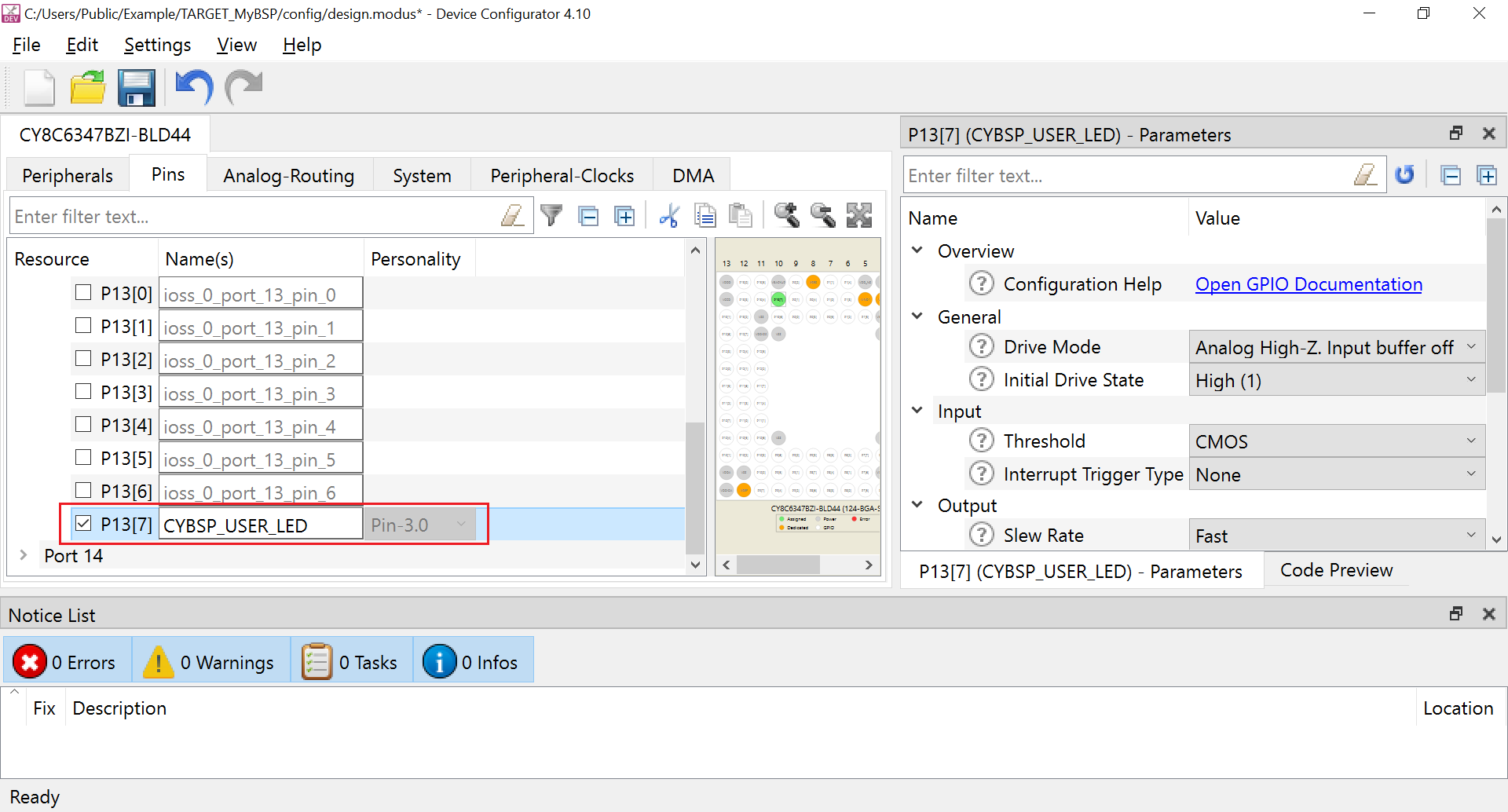
Figure 11. Changing clock settings 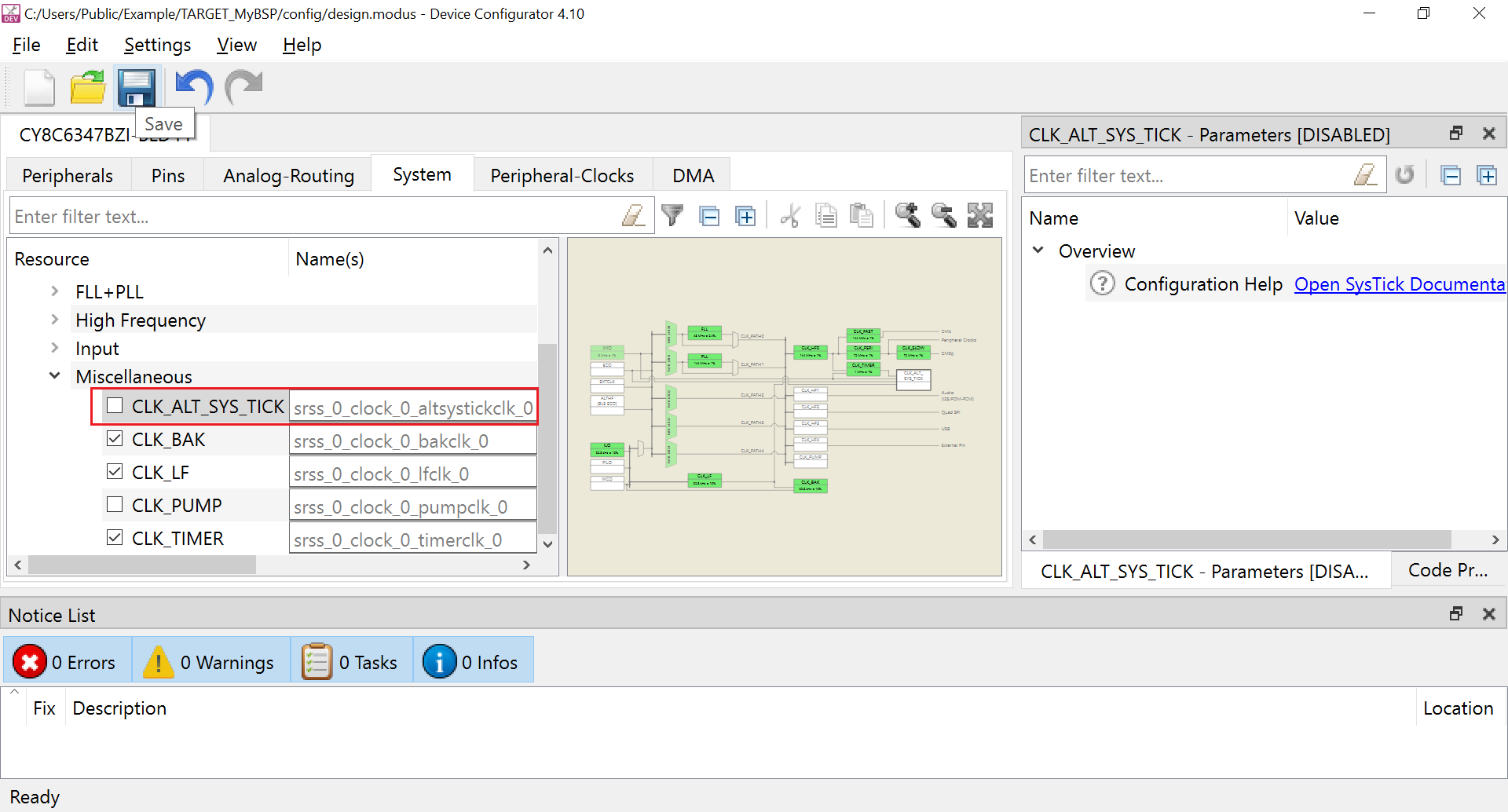
Click and then click .
Close the Device Configurator tool.
On the BSP Assistant tool, under the Libraries section, check that the BSP includes the following dependent libraries that will be used for an application:
cat1cm0pcore-libcore-makemtb-hal-cat1mtb-pdl-cat1receipe-make-cat1a
Figure 12. Checking libraries 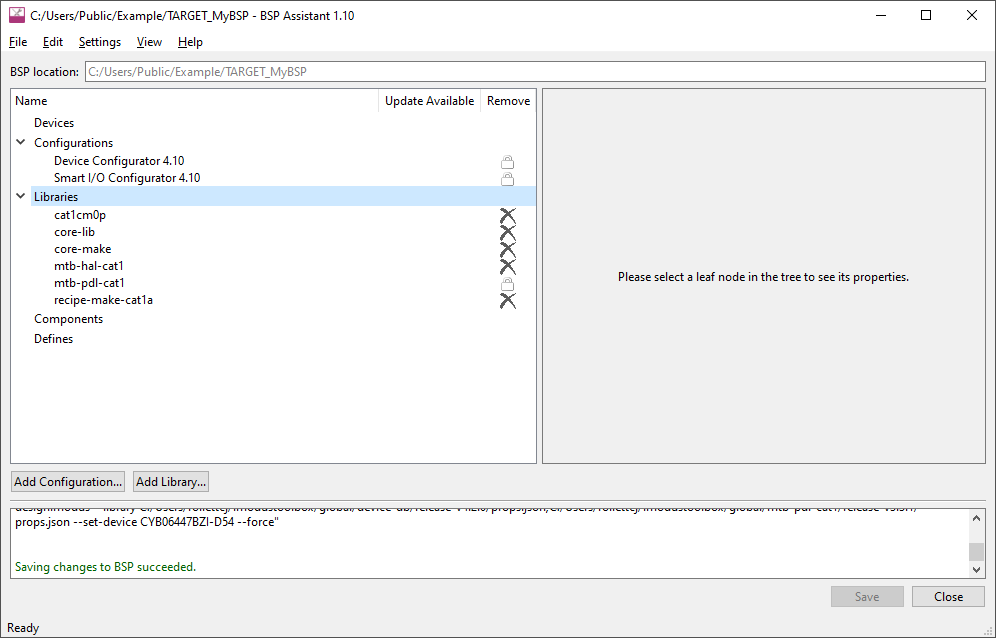
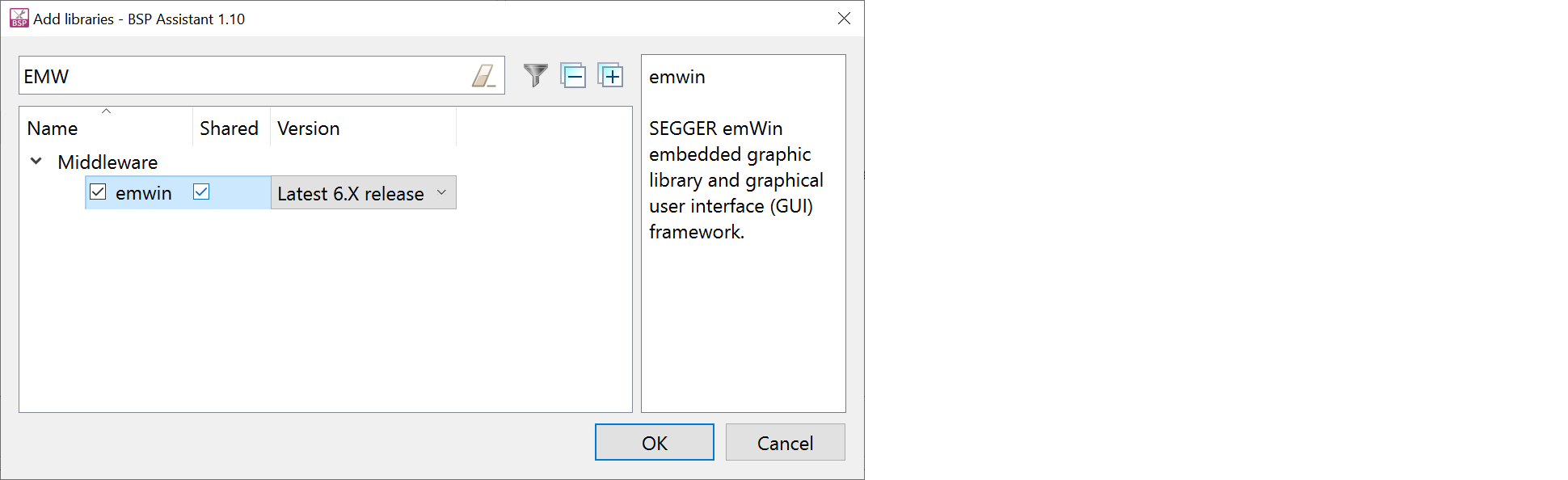
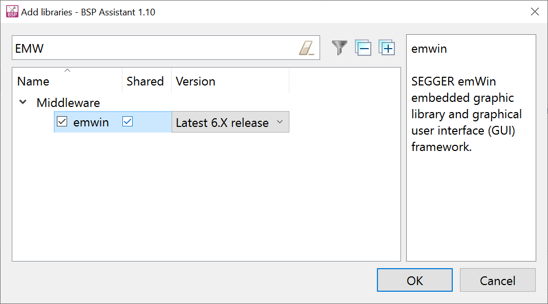
If you need any additional Libraries other than those listed above, click Add Library button to view the list of available libraries. For example, the following image shows adding the emwin package.
Note: If you click the filter button, only enabled dependencies will be listed.Figure 13. Adding "emwin" to the list of libraries 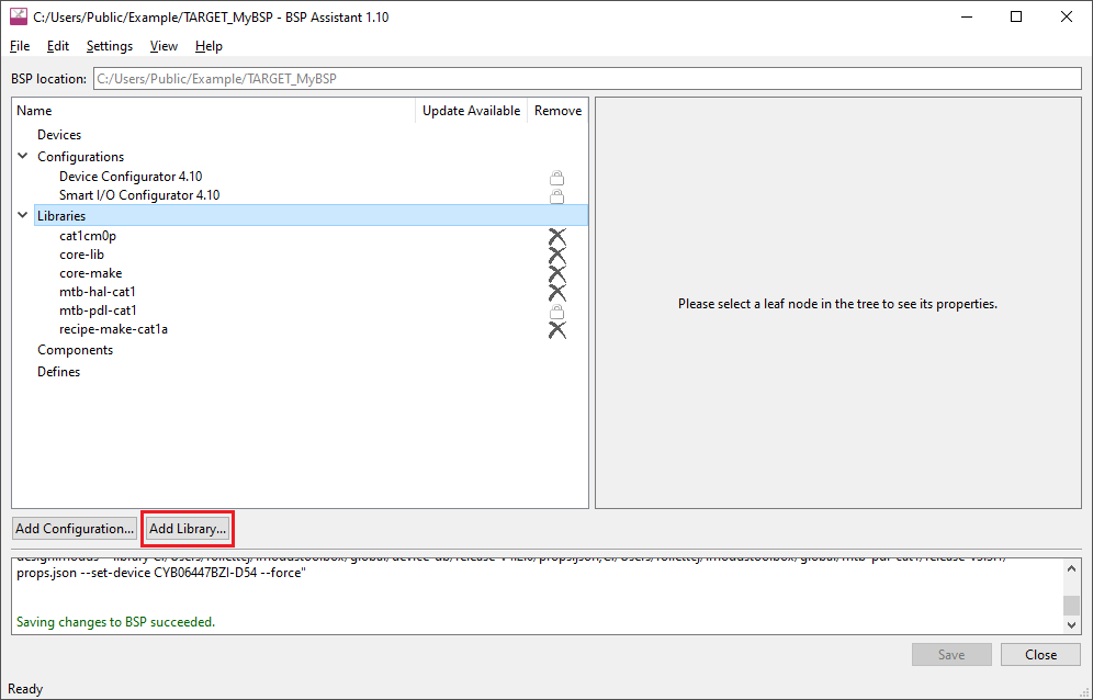
After the necessary libraries are added, click the Save button to save the BSP.
Figure 14. Saving the updated BSP 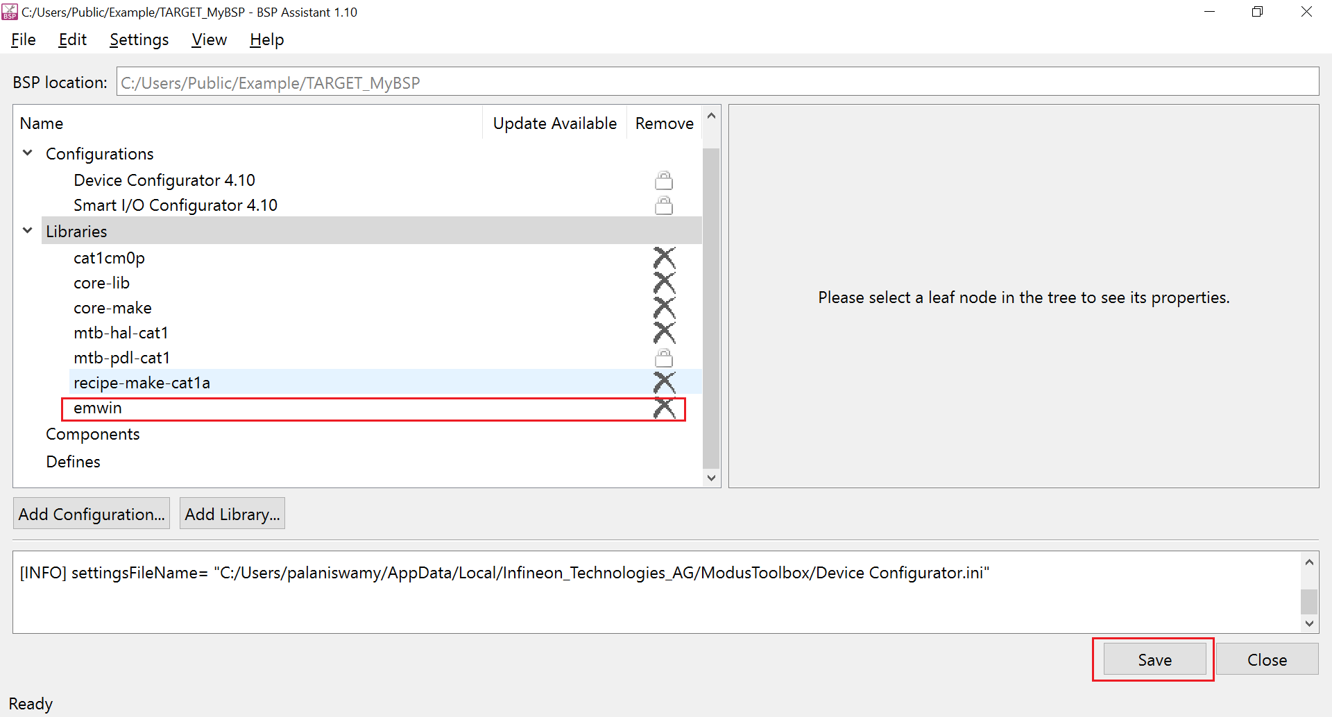
Otherwise, there will be a warning as shown when you exit the tool.
Figure 15. BSP saving missed warning 
This completes the BSP creation; you can exit the tool now. If you changed any libraries, you might see the following warning while leaving the tool; you can ignore the warning since the BSP is not yet being used in any applications:
Figure 16. Warning can be ignored 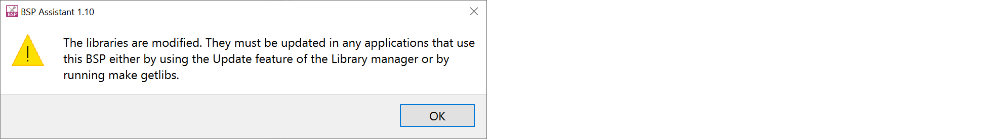
Create and configure the BSP using MPN
Type bsp-assistant in the Windows search tool to open the BSP Assistant tool or look in the Windows menu under "ModusToolbox <version>".
After the tool loads, select to open the Create New BSP window.
Figure 17. Create New BSP window 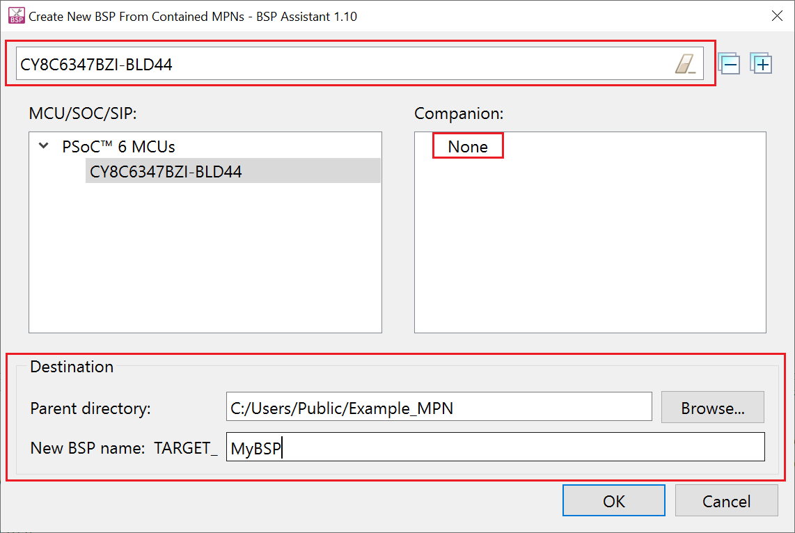
Enter the first few characters of the MPN CY8C6347BZI-BLD44 in the search bar and select the MPN CY8C6347BZI-BLD44 in the pane MCU/SOC/SIP from the results.
Select None in the Companion paneas the BSP we create in the example does not have any connectivity device connected to the MCU.
Set the directory path where the BSP will be created in the Parent Directory text box.
Type a suitable name for the BSP in the New BSP name: TARGET_ text box. This example uses the name MyBSP.
Click OK.
The BSP Assistant tool starts downloading the contents from the Infineon GitHub website; when finished, the screen should look like the following. Ignore any warnings in the bottom pane at this stage, as it will be fixed in the following steps.
Figure 18. BSP Assistant finished loading content 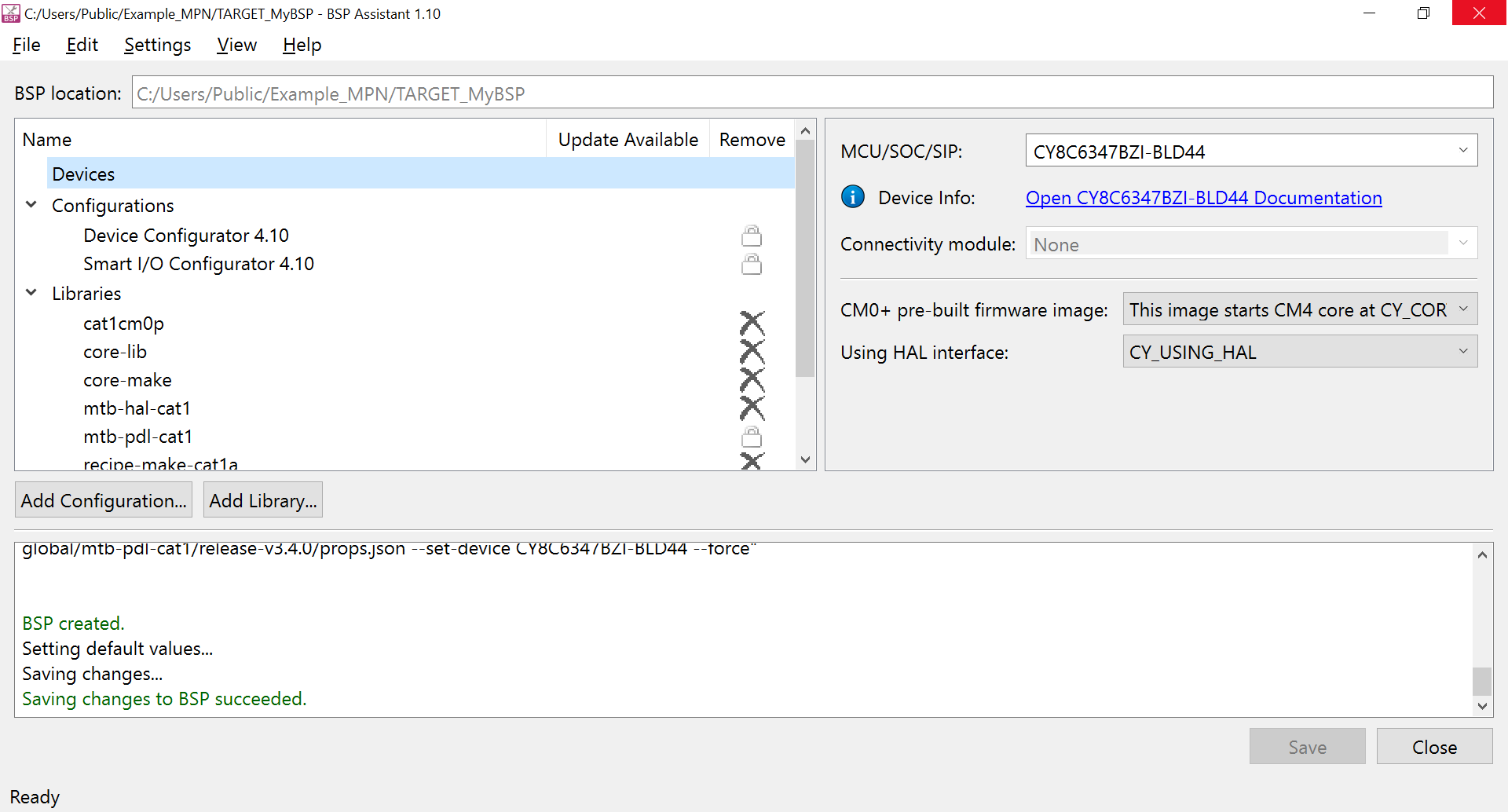
Select the Device Configurator 4.10 from the Configurations item in the left pane. Then click the Edit Configuration button to update the MCU configuration to match that of the BSP created in section 3.1.1.
Figure 19. Opening the Device Configurator 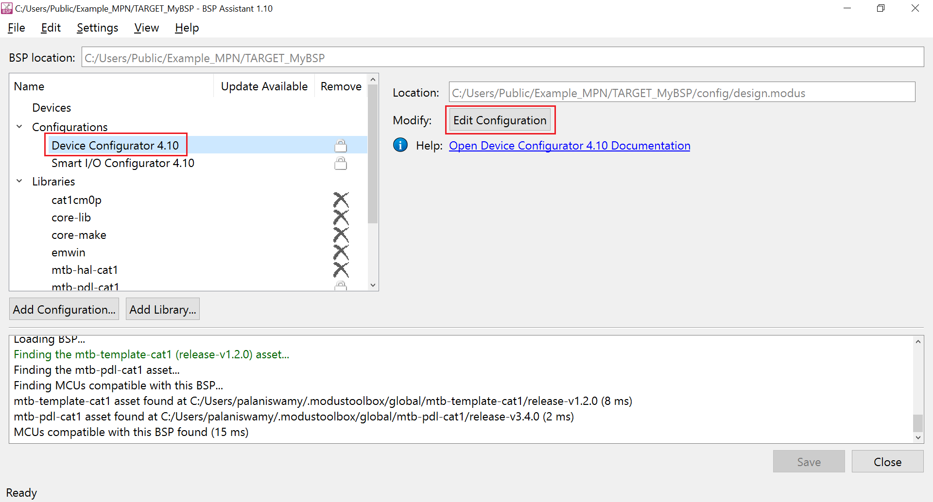
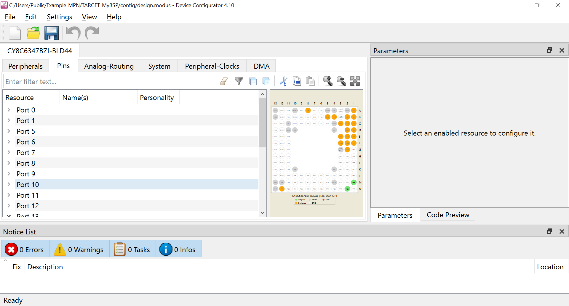
Enable and add the name for the following pins in the Device Configurator.
Table 2. Adding identifier to the pin Port and pin number Name P5[0] CYBSP_DEBUG_UART_RX P5[1] CYBSP_DEBUG_UART_TX P6[4] CYBSP_SWO P6[6] CYBSP_SWDIO P6[7] CYBSP_SWDCK P13[7] CYBSP_USER_LED Figure 20. Adding identifier to the pin 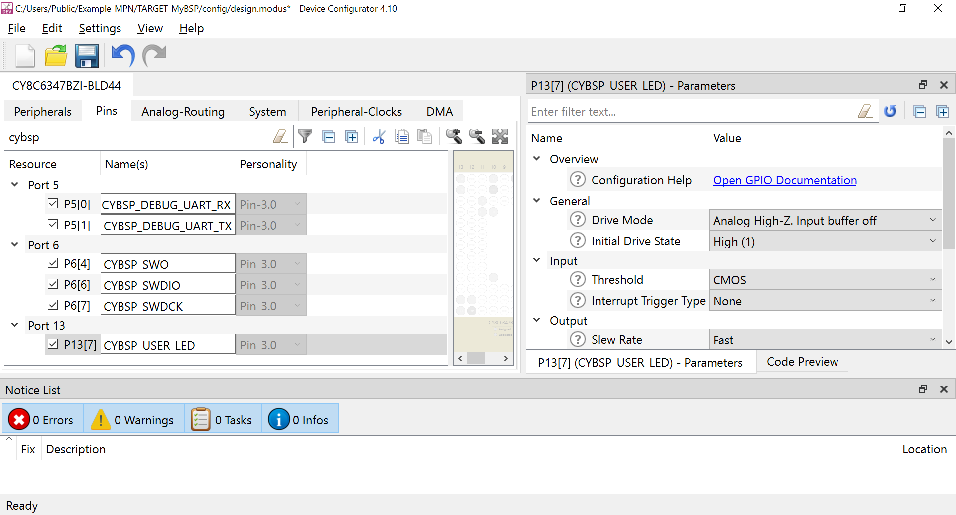
For the pin P6[4], set the Drive Mode in the Parameter pane to Strong Drive. Input buffer off.
Figure 21. Updating the pin drive mode setting 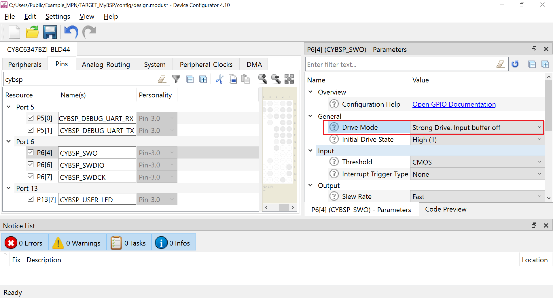
Update the following settings in the block:
- Enable the FLL
- Set the Desired Frequency (MHz) as 48.000
Figure 22. Updating the FLL settings 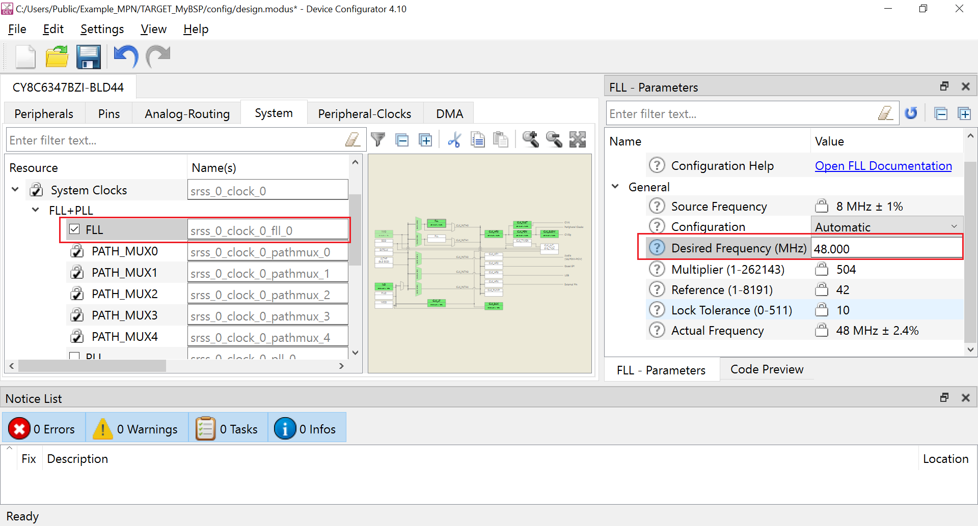
Update the following settings in the System > System Clocks block:
- Enable the PLL
- Set the Desired Frequency (MHz) as 144.000
Figure 23. Updating the PLL settings 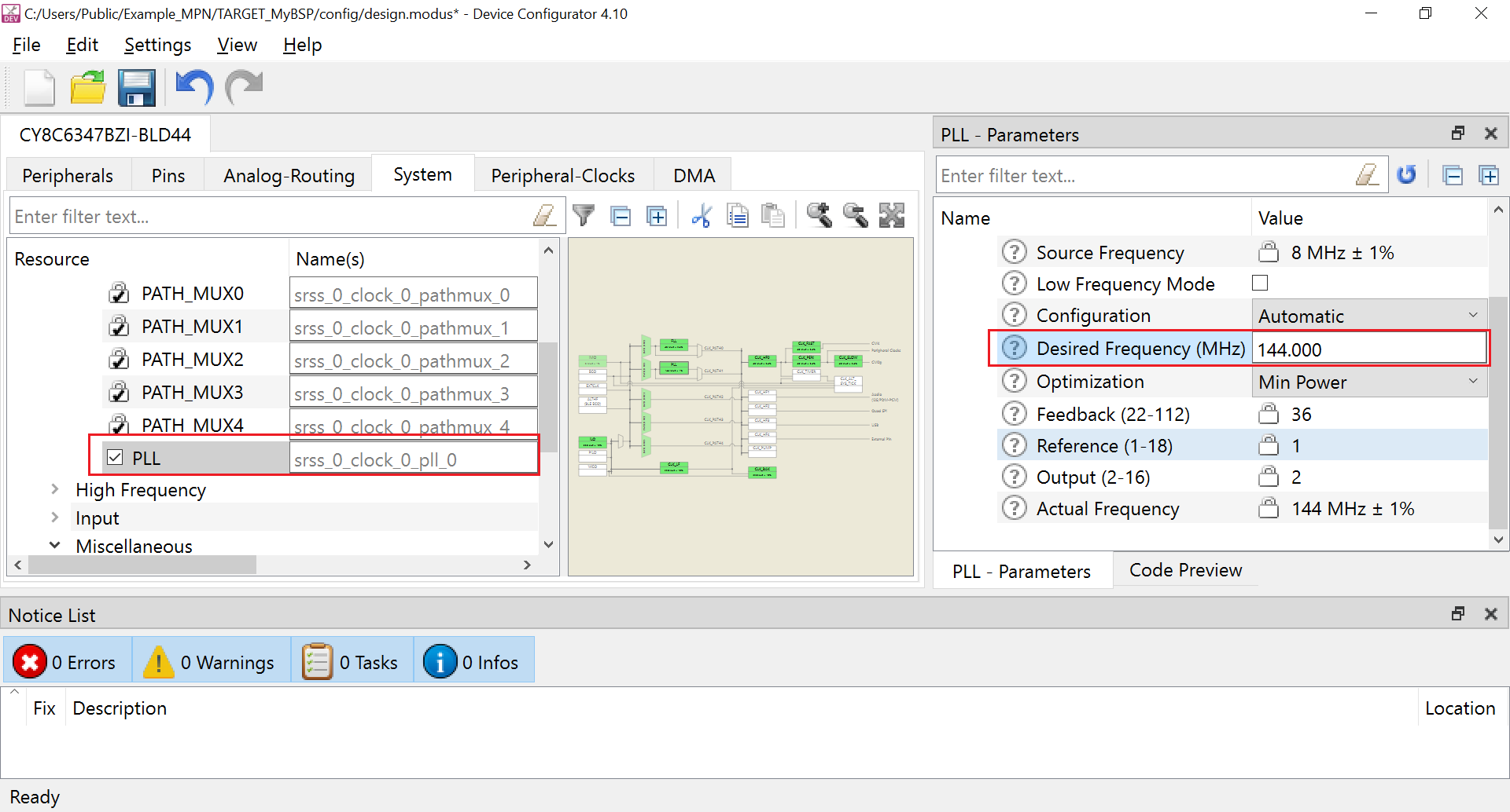
On the System > System Clocks > High Frequency block, update the following settings:
- Set the Source Clock for CLK_HF0 as CLK_PATH1
- Set the Divider for CLK_PERI as 2
On the System > System Clocks > Miscellaneous block, update the following settings:
- Enable the CLK_TIMER
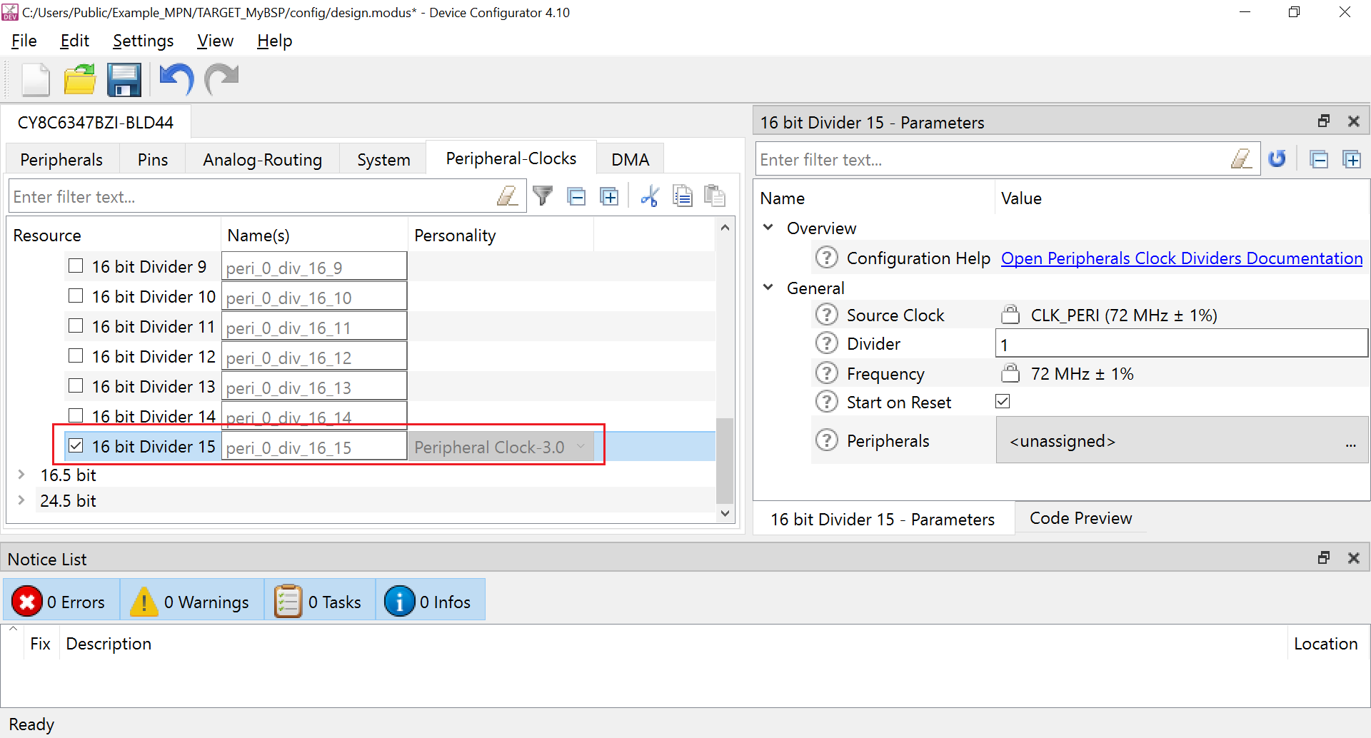
On the Peripheral-Clocks tab, update the following settings:
- Update the name for 8 bit > 8 bit Divider 7 as CYBSP_TRACE_CLK_DIV
- Enable the 16 bit > 16 bit Divider 15 clock
Figure 24. Updating the Clock Dividers 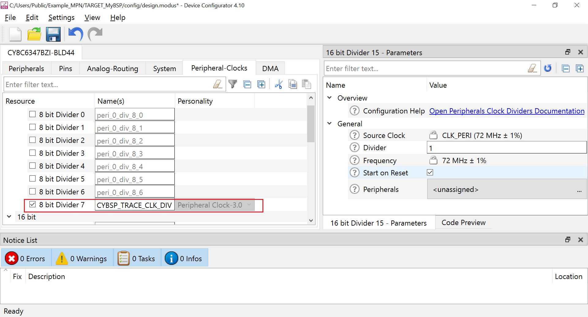
On the System > Debug tab, update the following settings:
- Enable Trace Mode-Serial setting
- Set the Trace Clock>Clock as 8-bit Divider 7 clk(CYBSP_TRACE_CLK_DIV) [USED]
- Set the Trace Pins>SWO as P6[4] digital_out(CYBSP_SWO)[USED]
Click File > Update All Personalities and then click File > Save.
Close the Device Configurator tool.
If you need any additional Libraries other than those listed above, click the Add Library button to view the list of available libraries. For example, the following image shows adding the emwin package.
Figure 25. Adding emwin to the list of libraries 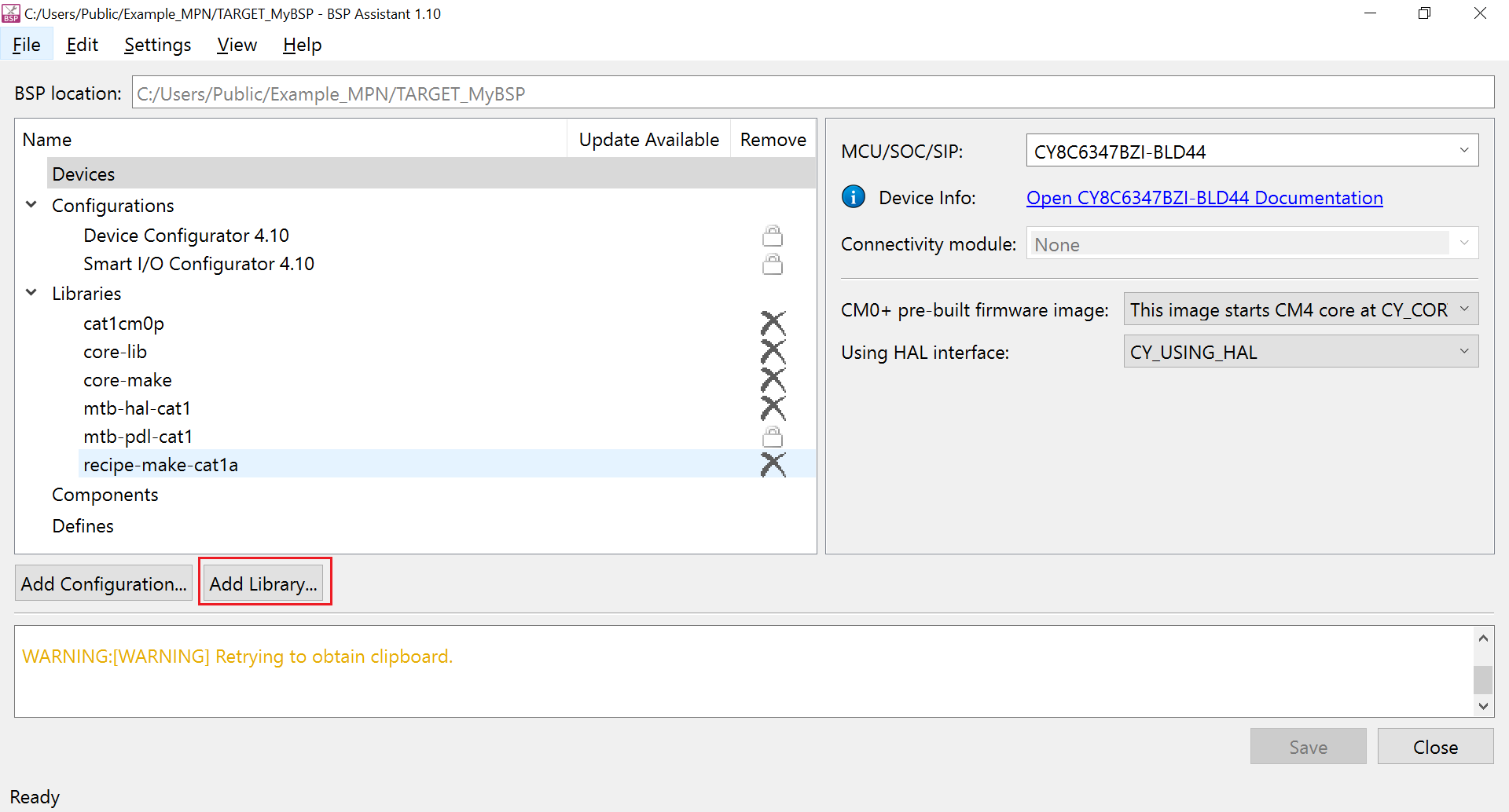
After the necessary libraries are added, click on Save button for saving the BSP.
Figure 26. Saving the updated BSP 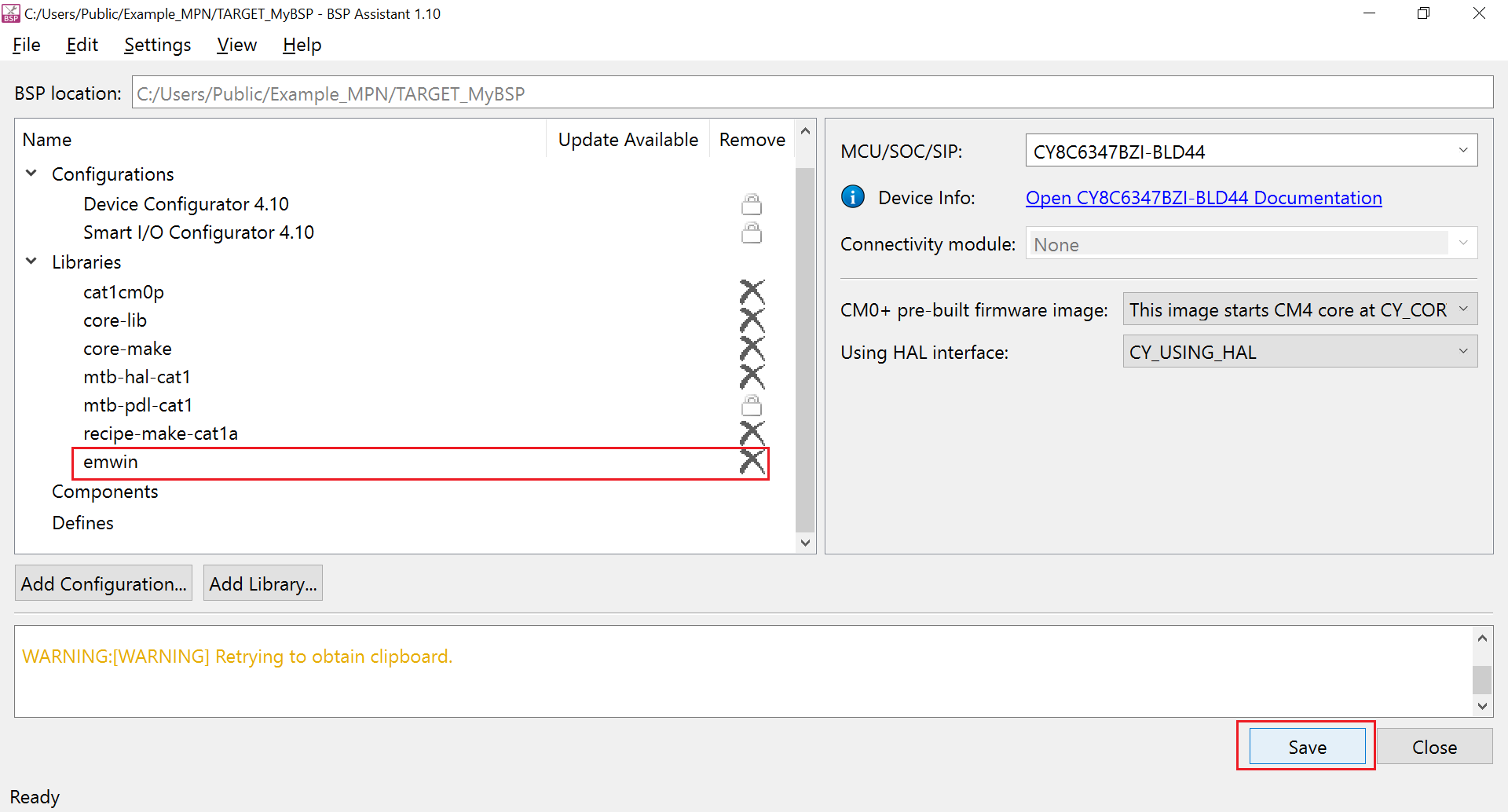
Click the Save button at the bottom to save the changes.
Figure 27. Saving the BSP 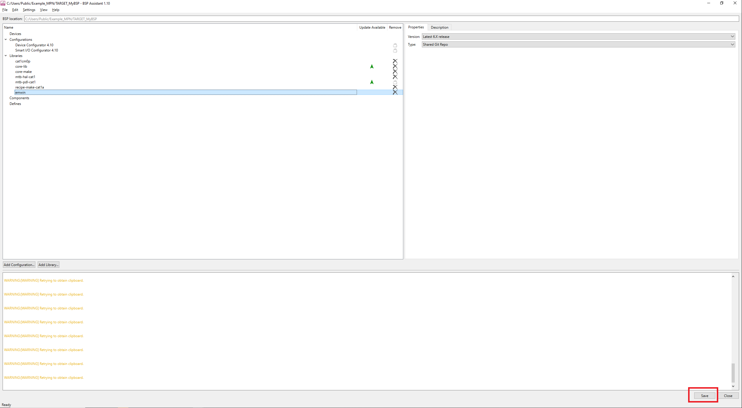
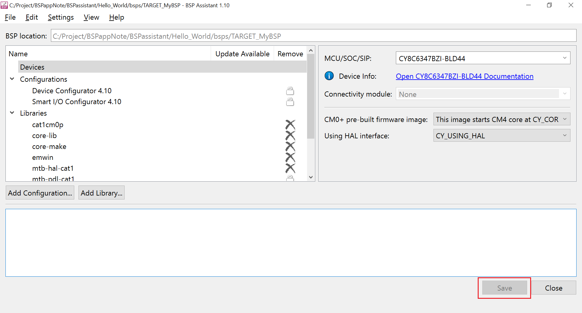
Otherwise, there will be a warning as below while exiting the tool.
Figure 28. Warning on missed BSP saving This completes the BSP creation; you can exit the tool now. If you changed any dependencies, you might see the following warning while leaving the tool; you can ignore the warning since the BSP is not yet being used in any applications.
Figure 29. Warning can be ignored 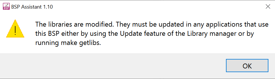
Create an application
With the BSP creation and configuration complete, create a Hello World application from a code example template using the following steps.
Open Eclipse IDE for ModusToolbox™ from the Windows start menu and create a workspace as follows:
Figure 30. Create Eclipse IDE workspace 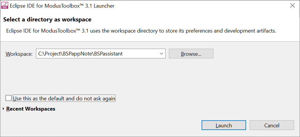
Click .
Figure 31. Create new ModusToolbox™ application 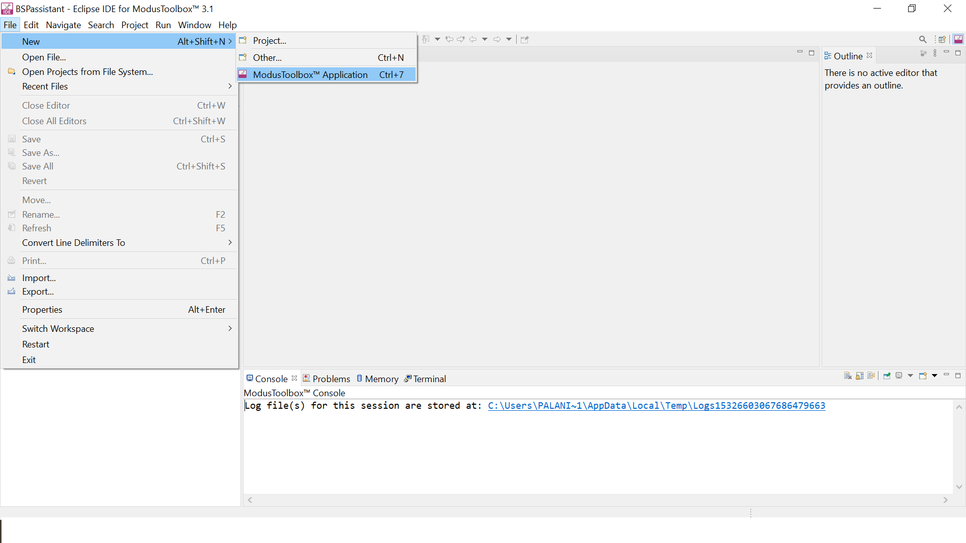
The Project Creator tool opens on the Choose Board Support Package window.
Figure 32. Project Creator tool 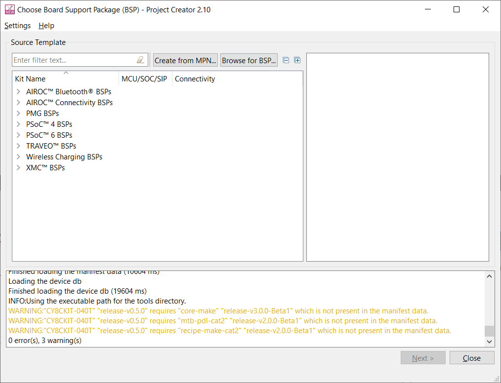
Select the BSP created in the previous section by clicking the Browse for BSP button and navigating to the directory containing the previously created BSP and choosing it.
Figure 33. Importing BSP 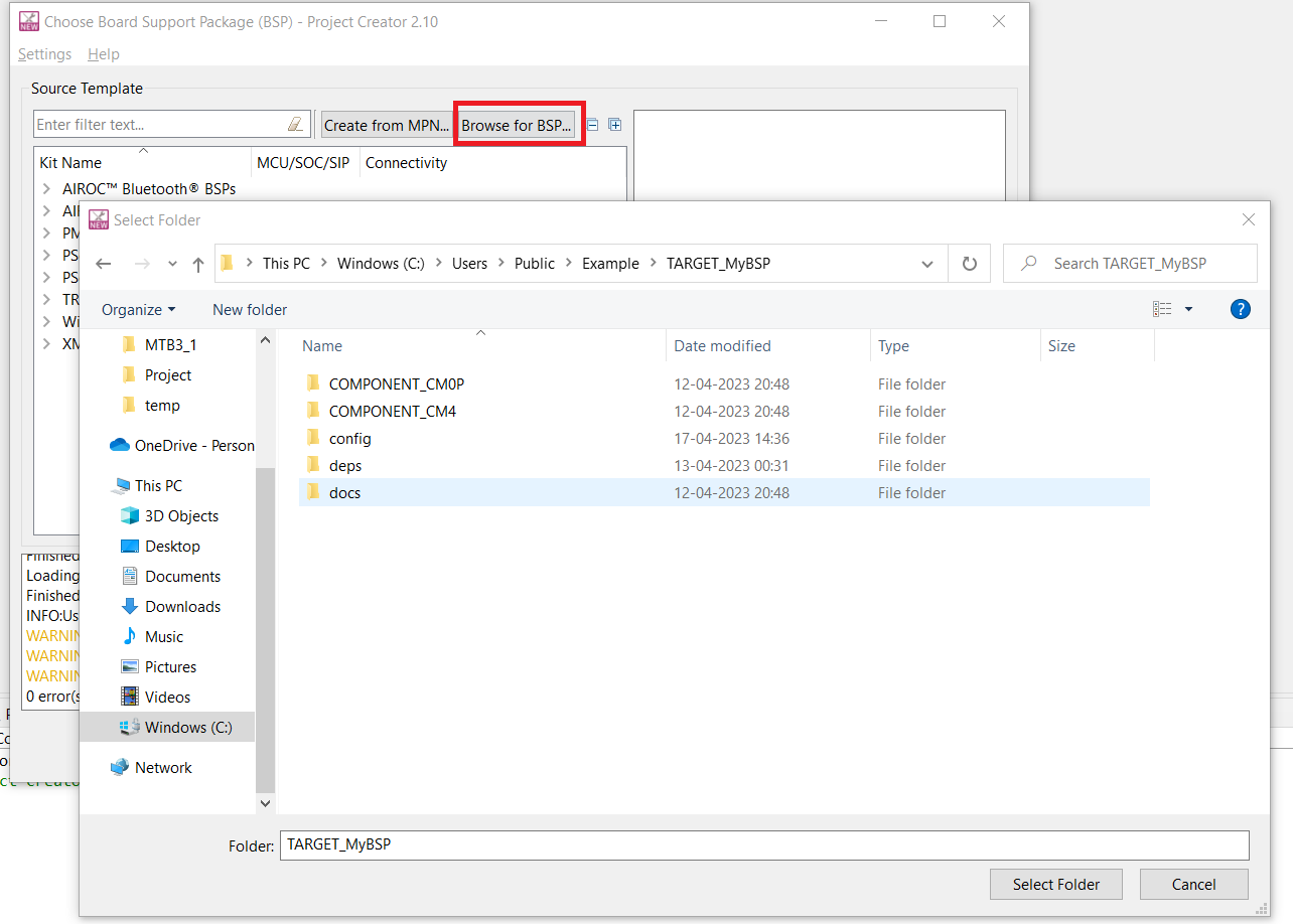
The BSP you selected is listed as shown. Select it and click Next >.
Figure 34. Selecting imported BSP 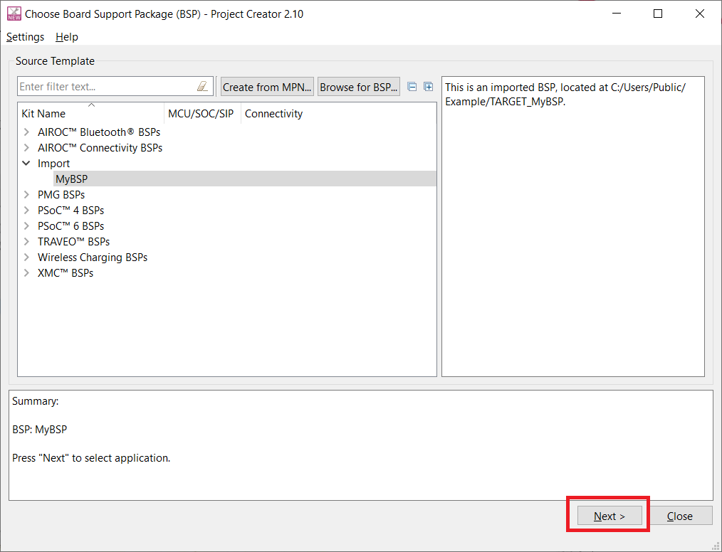
On the Select Application page, select Hello World from the template application under Getting Started. Enter a new name to the application such as Hello_World under the New Application Name column as shown. After that, click Create.
Figure 35. Select Application 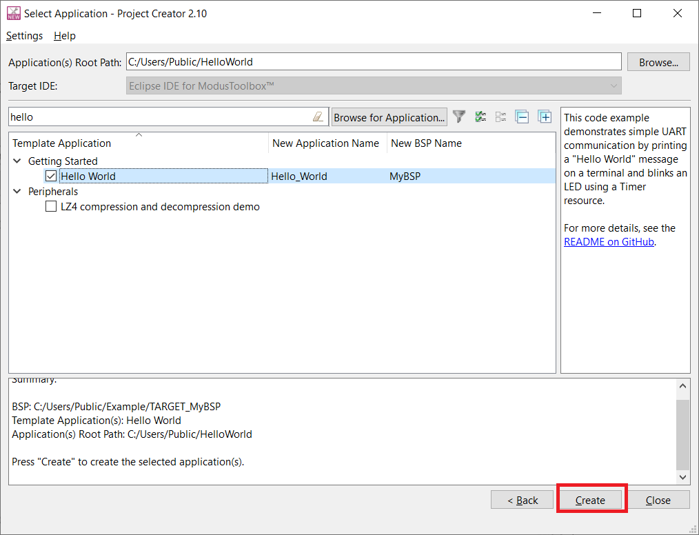
The application download from GitHub starts and after successful completion, the project will be visible in the Eclipse IDE Project Explorer as follows:
Figure 36. New application in Eclipse IDE for ModusToolbox™ 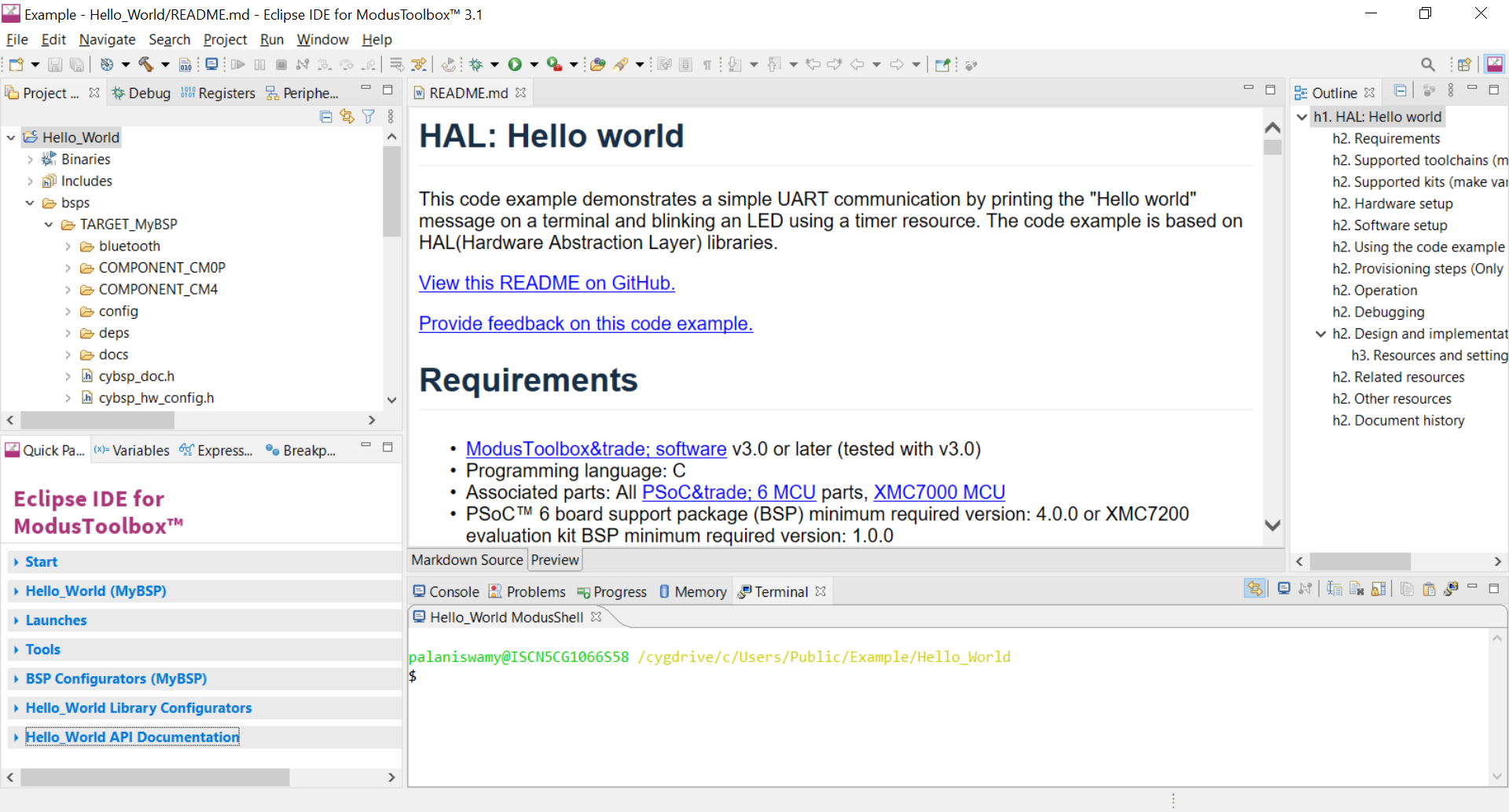
Code Build
Click Build Application in the Quick Panel pane as follows. If there are no errors, the build should pass successfully.
Figure 37. Successful build 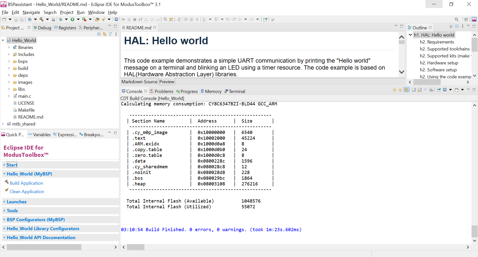
This completes the use case demonstration.
Customizing an existing BSP
This use case happens when you want to make changes to an existing BSP. There are two cases:
Open and edit existing BSP on its own
The steps below show example updates to an existing BSP using the BSP created in the section Create and configure the BSP using the existing sample board. These updates to the BSP are just for demonstration. The user may perform updates depending on their application requirements. The following changes are made on top of the previous BSP:
- Add the
freertosandretarget-iolibraries - Add the corresponding component definition for the
freertoslibrary that was added in the above step - Adding a new macro to enable the conversion of LF to CR&LF in STDOUT while
using
retarget-iolibrary
Open the BSP Assistant application. Click
Figure 38. Open existing BSP 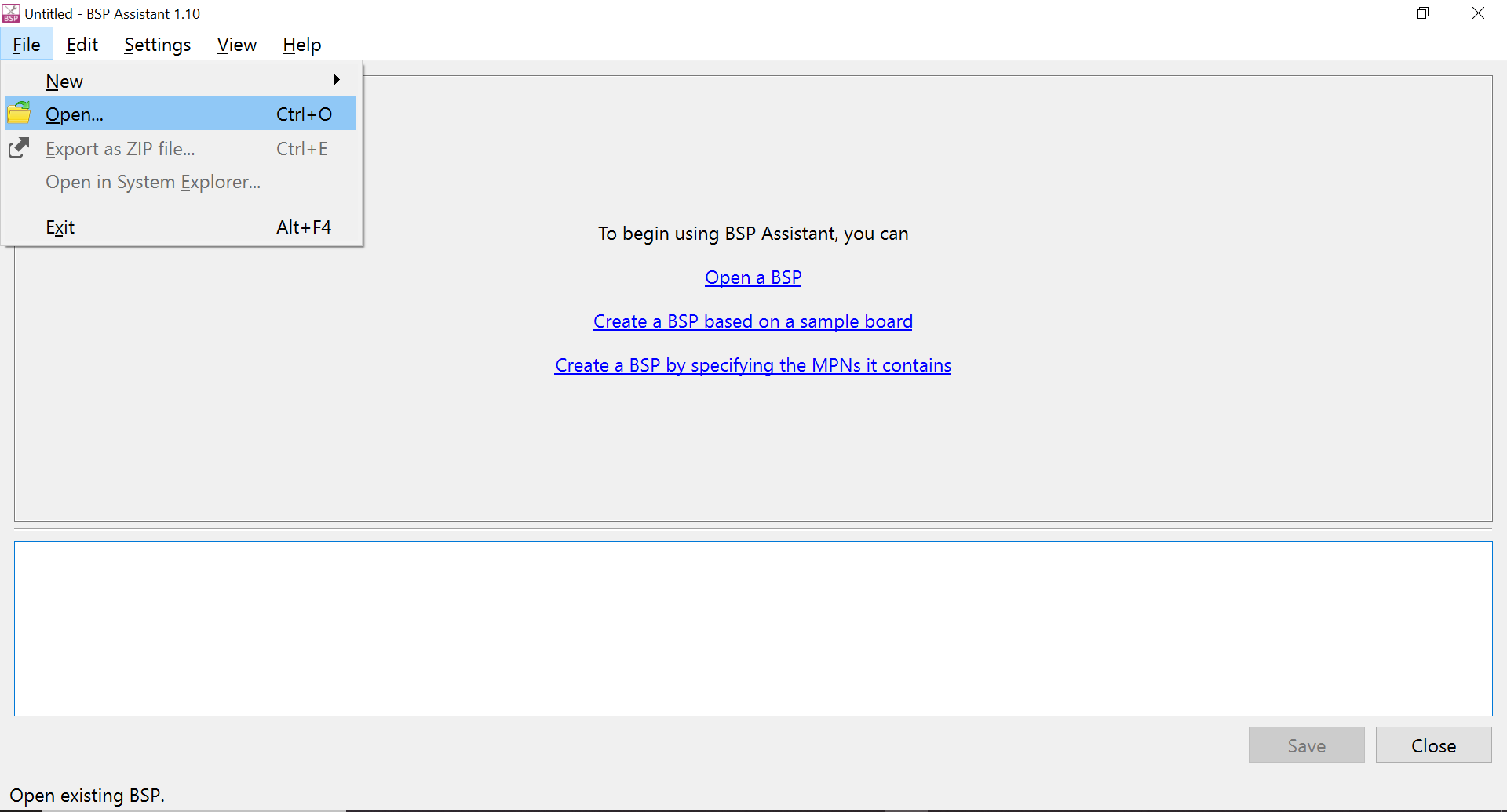
To browse the directory containing the existing BSP, click Select Folder button to open the BSP in the BSP Assistant application.
Figure 39. Browse Existing BSP 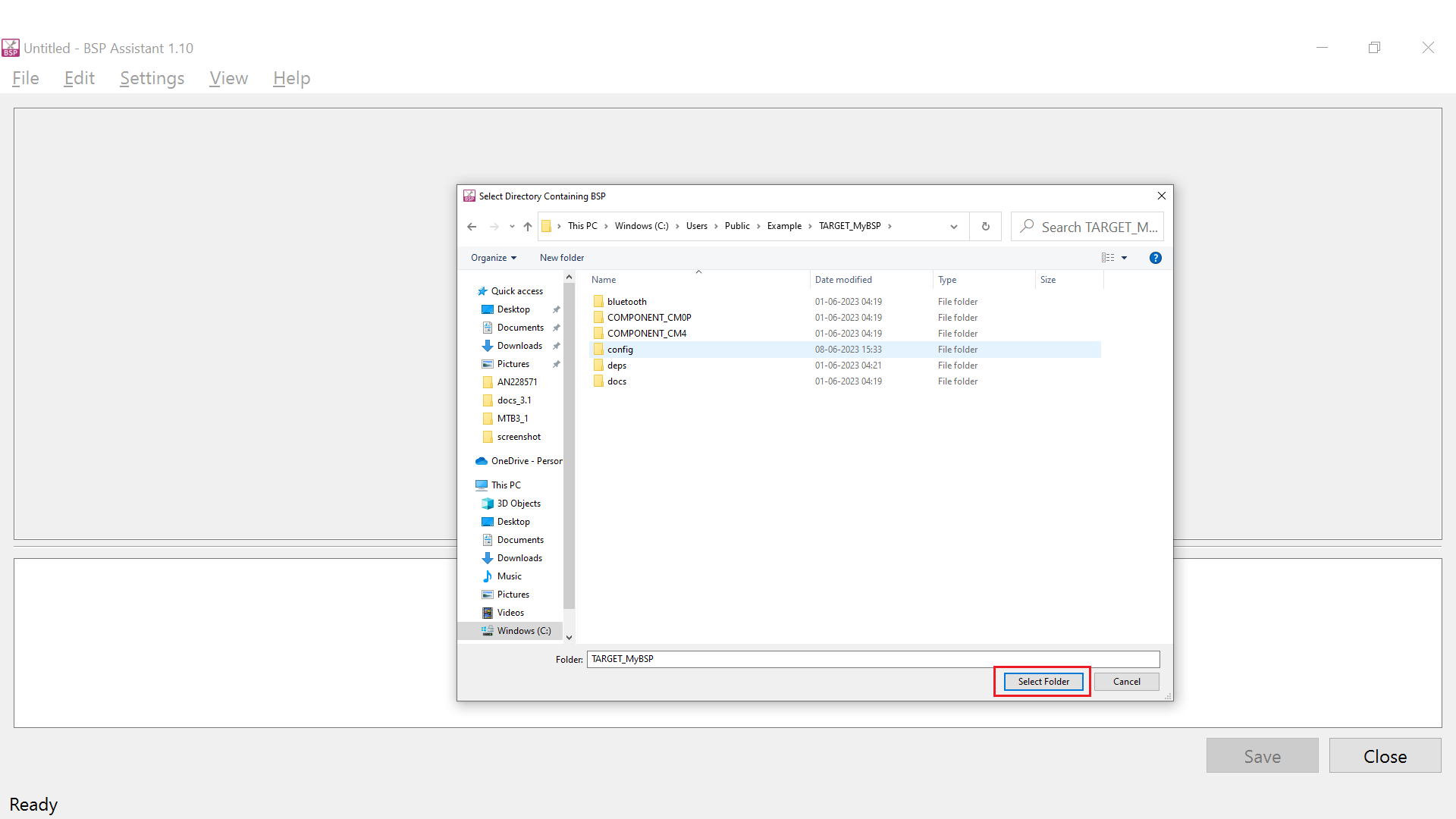
The following window opens:
Figure 40. BSP opened in BSP Assistant 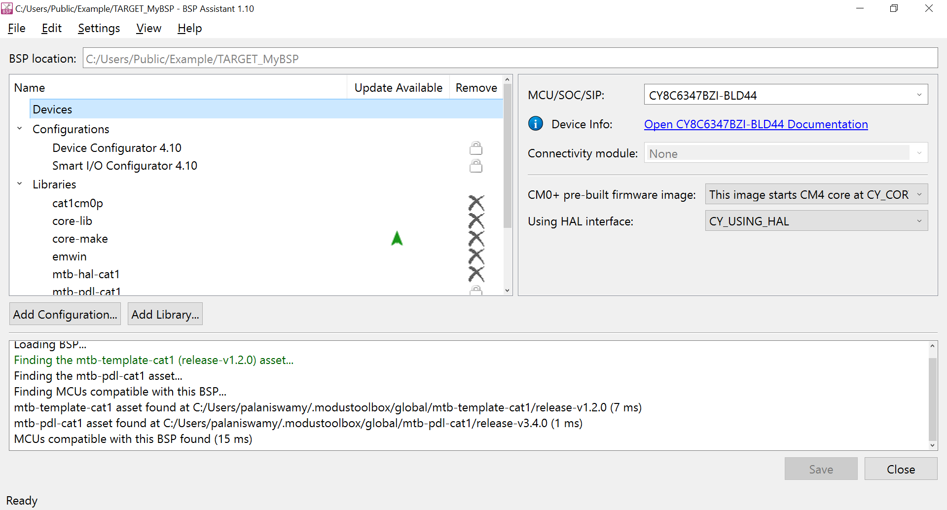
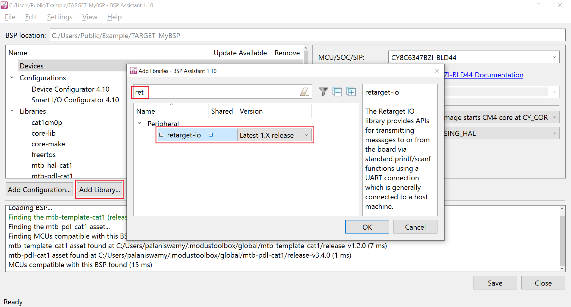
Click the Add Library button and select the check boxes to add
freertosandretarget-iolibraries. Click OK after selecting the libraries to add them to the BSP. You can use the filter box at the top of the window to narrow down the list of libraries.Figure 41. Adding libraries 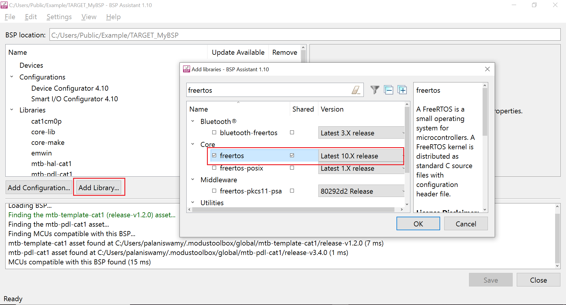
To add a component, do the following:
Click the Components section
Click Edit Additional Components…
In the Component to add field, enter FREERTOS
Click Add
If you do not have additional component to add, click OK
This closes the Edit Component window.
Figure 42. Add a component 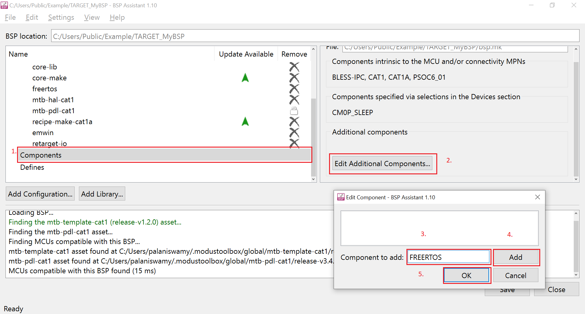
To add a define, do the following:
Click the Defines section
Click Edit Additional Defines..
In the Define to add field, enter
CY_RETARGET_IO_CONVERT_LF_TO_CRLFClick Add
Since we have no additional defines to add, click OK
This closes the Edit Defines window.
Figure 43. Add a define 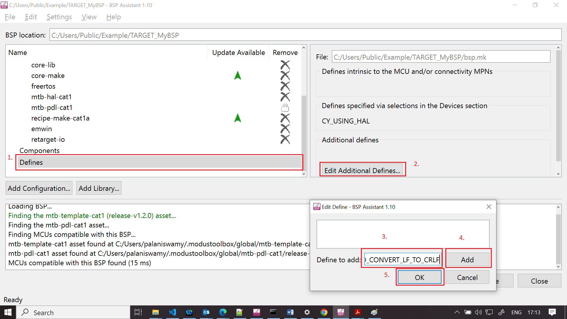
Click the Save button to save the changes.
Figure 44. Save updated BSP 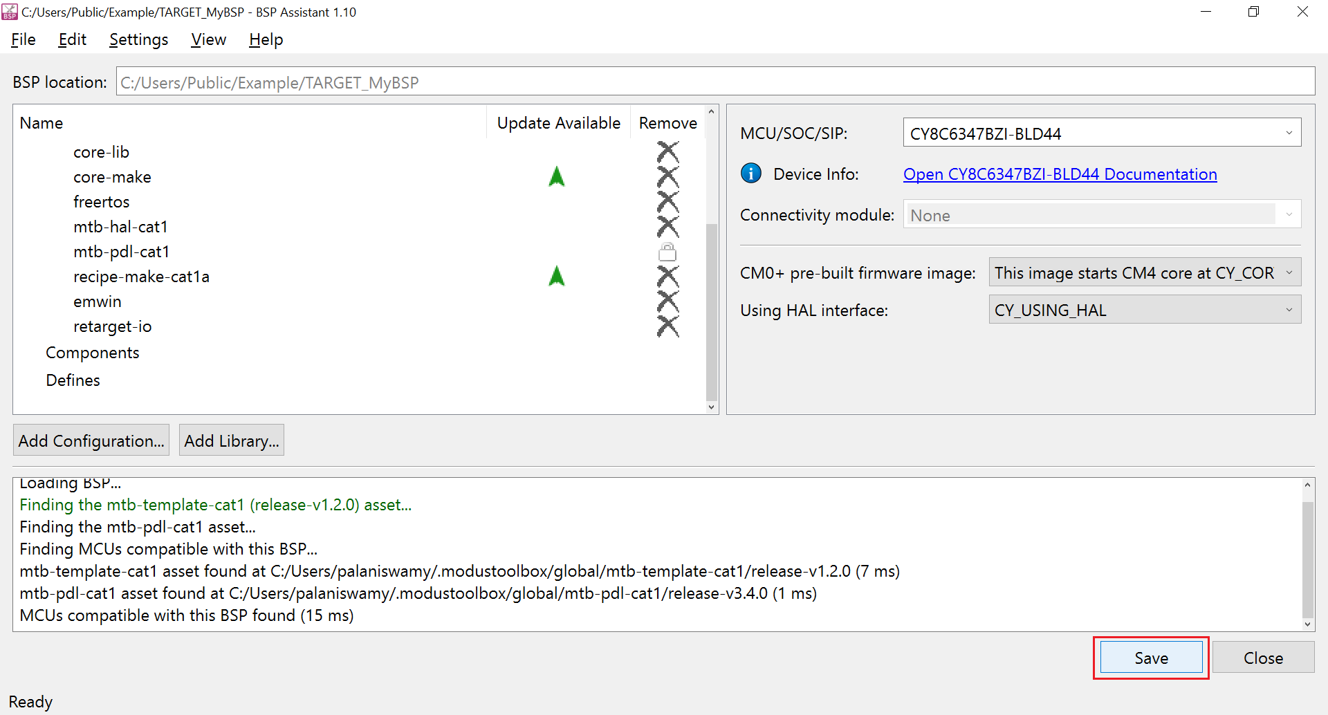
A Saving changes to BSP succeeded. message shows in the console window.
Figure 45. Save message 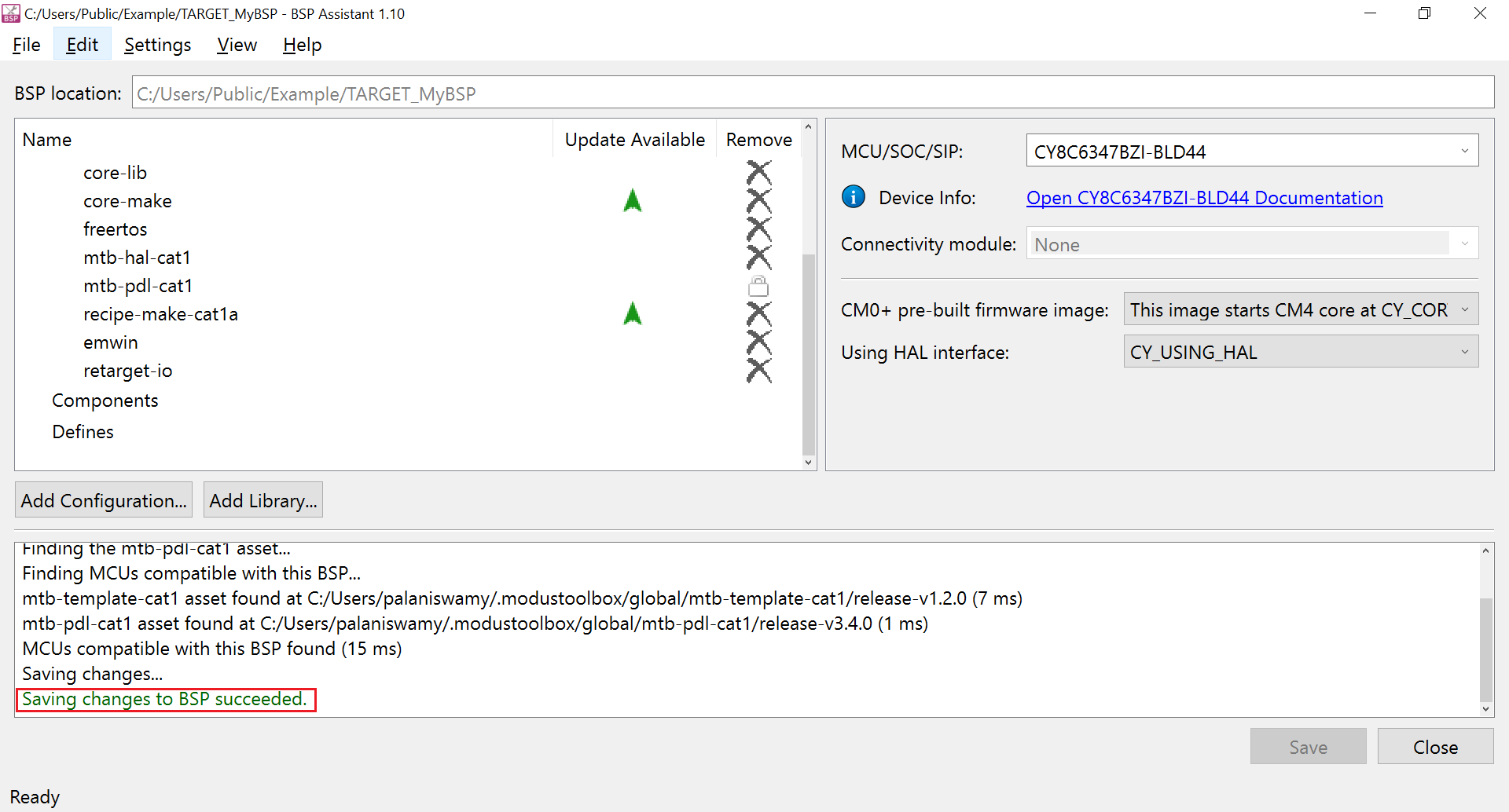
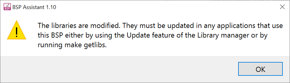
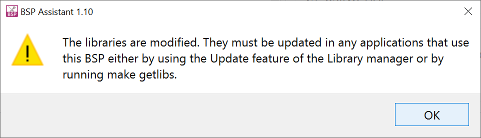
Click the Close button to close the BSP Assistant. While exiting, a warning is displayed to update the application using the library manager. This warning can be ignored as we are yet to create an application from this BSP.
Figure 46. Library update warning 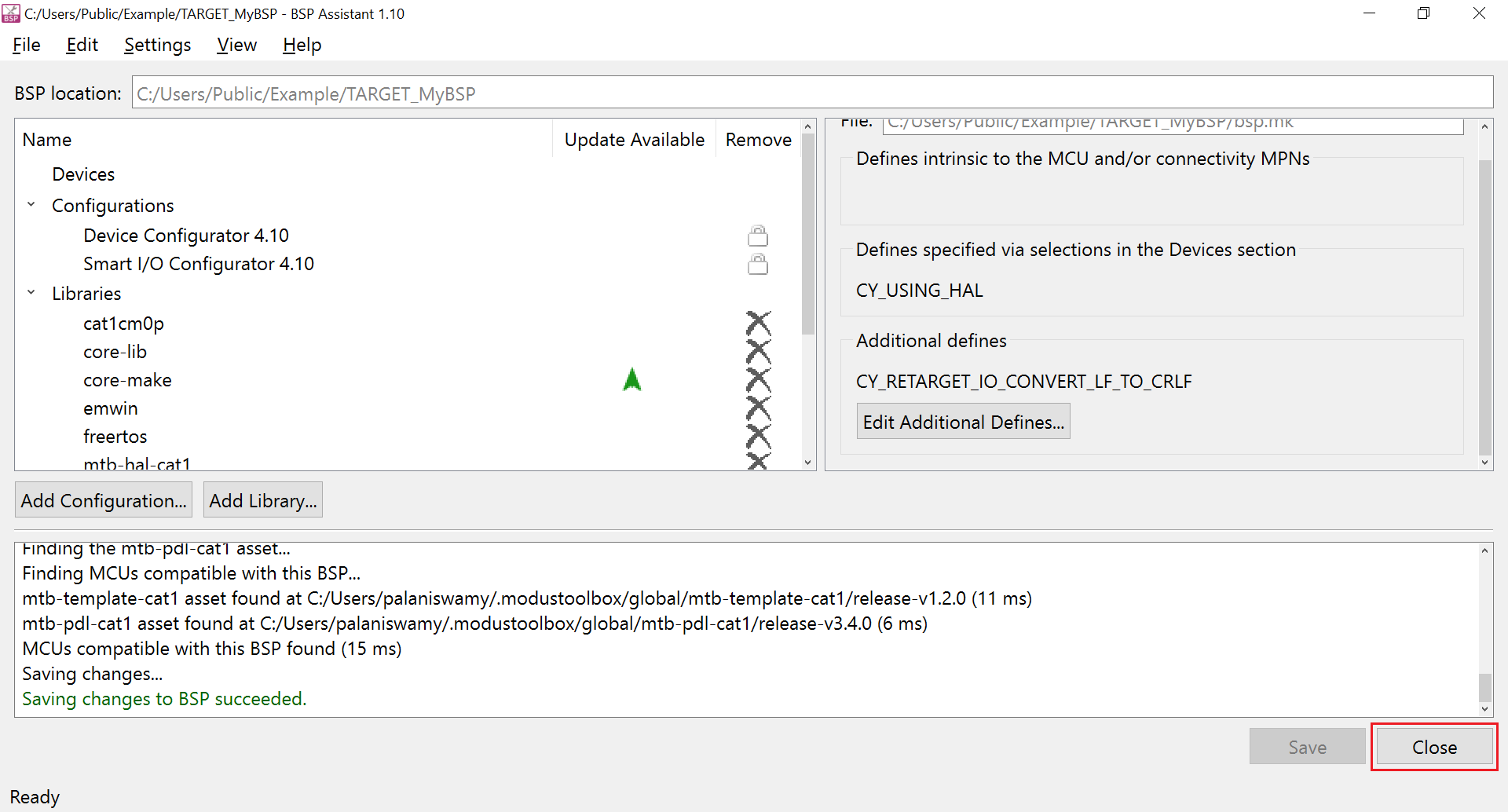
Open and edit an existing BSP from an application
The steps below show an example update to the BSP that is already part of an application. The application that was created in the Create an application section will be used as the starting point. These updates to the BSP are just for demonstration purposes. The user may choose updates depending on his/her updated application requirements.
The following changes are made on top of the previous BSP:
- Add the
freertoslibrary - Add the corresponding component definition for the
freertoslibrary that was added in the above step - Add a new macro to enable the conversion of LF to CR&LF in STDOUT while using the
retarget-iolibrary
Open the Eclipse IDE for ModusToolbox™ from the Windows start menu. Click Browse to browse the previously created workspace directory containing the application and then click the Launch button.
Figure 47. Open an application in Eclipse IDE 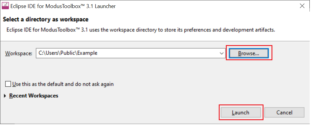
When the application finishes loading in the Eclipse IDE, you can run the BSP Assistant tool by clicking the BSP Assistant <version> link in the Quick Panel as shown.
Figure 48. Launching BSP Assistant 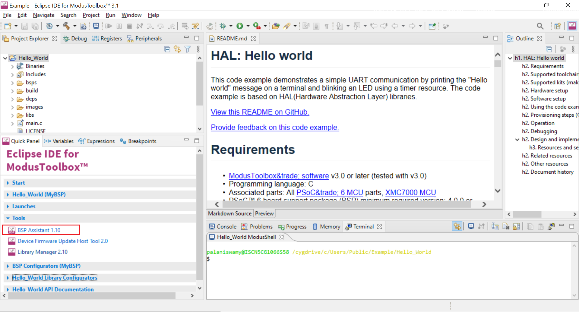
Click the Add Library button to add the freertos library. Click OK after selecting the library to add the library to the BSP.
Figure 49. Add Library 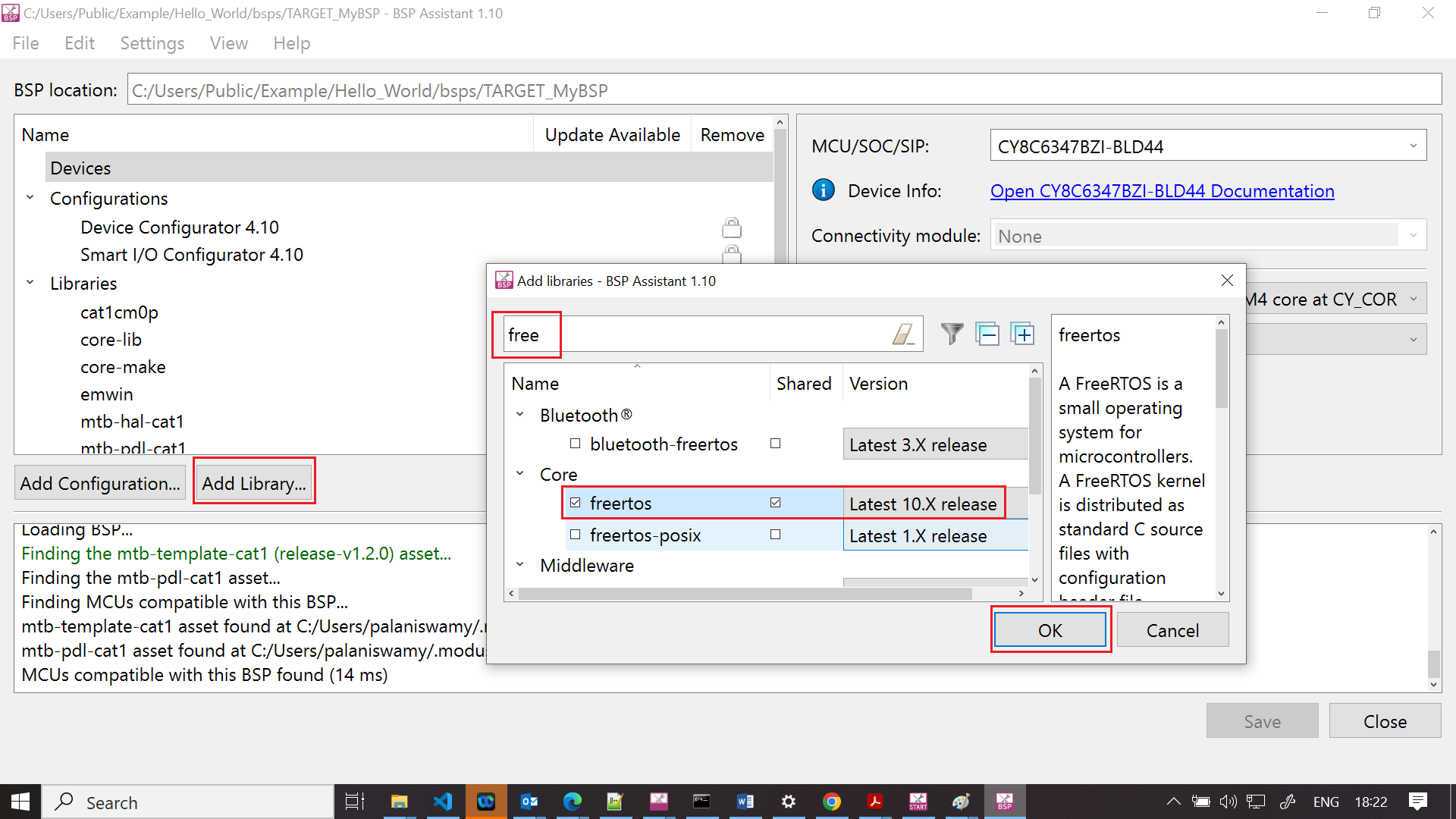
To add a component, do the following:
Click the Components section
Click Edit Additional Components…
In the Component to add field, enter FREERTOS
Click Add
If you do not have additional component to add, click OK
This closes the Edit Component window.
Figure 50. Add a component 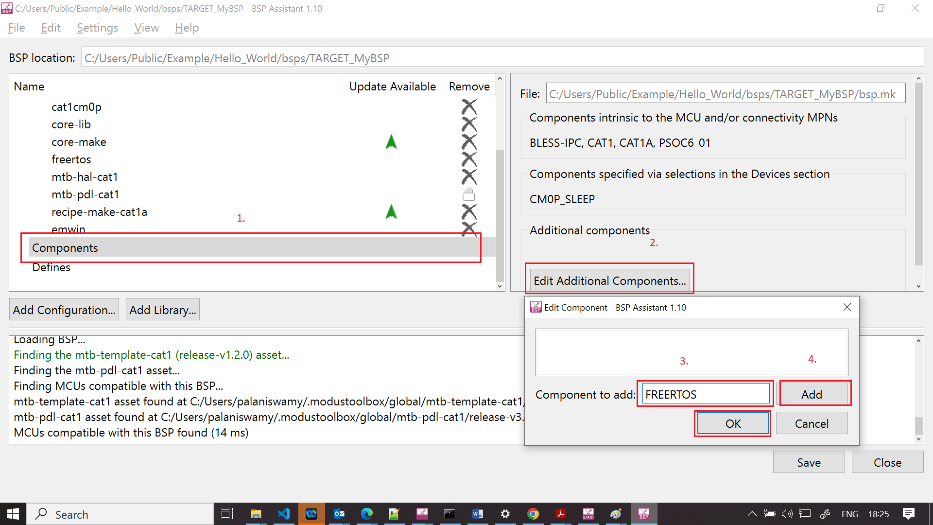
To add a define, do the following:
Click the Defines section
Click Edit Additional Defines..
In the Define to add field, enter
CY_RETARGET_IO_CONVERT_LF_TO_CRLFClick Add
Since we have no additional defines to add, click OK
This closes the Edit Defines window.
Figure 51. Add a define 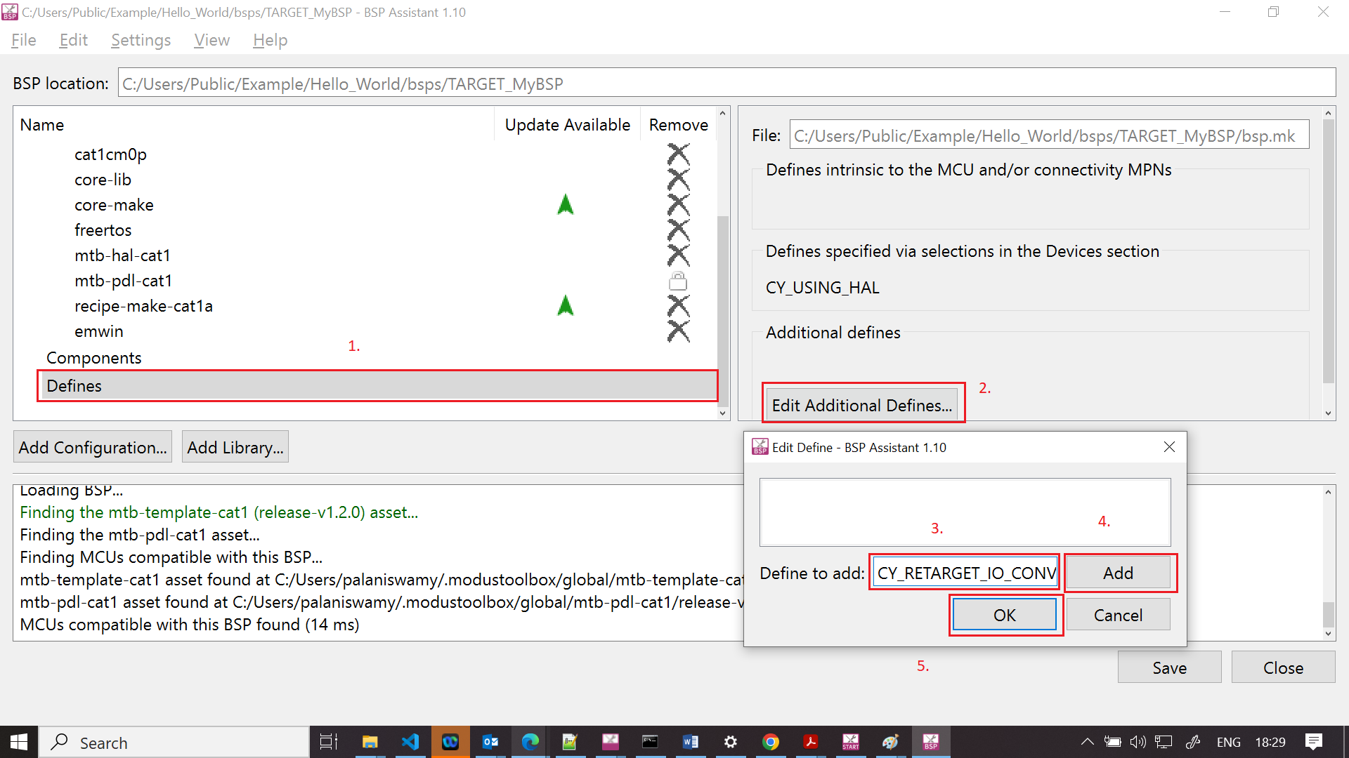
Click the Save button to save the changes.
Figure 52. Save Updated BSP 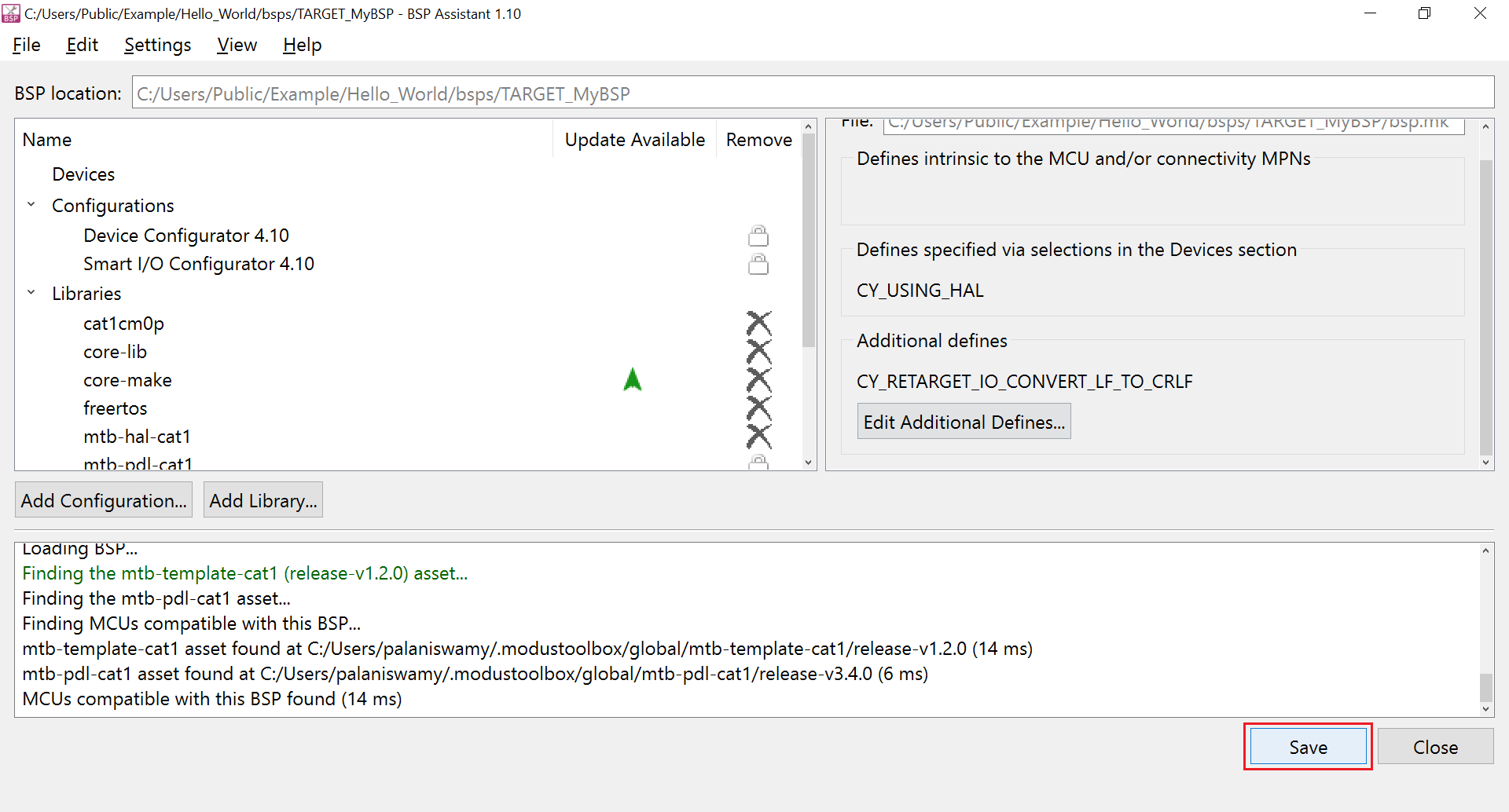
A Saving changes to BSP succeeded. message shows in the console window.
Figure 53. Save message 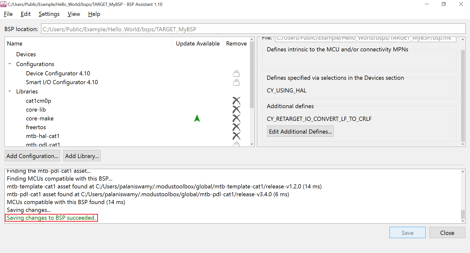
Click the Close button to close the BSP Assistant. While exiting, a warning is displayed to update the application using the library manager. You can run library manager after closing the BSP Assistant tool.
Figure 54. Library update warning 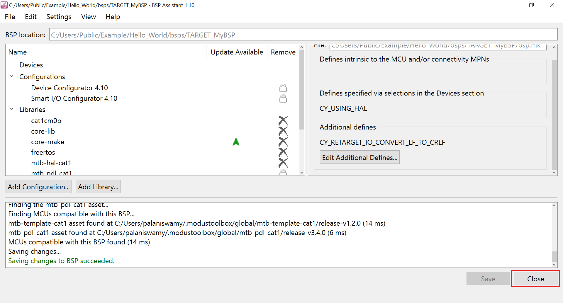
Click the Library Manager link in the Quick Panel.
Figure 55. Launch Library Manager 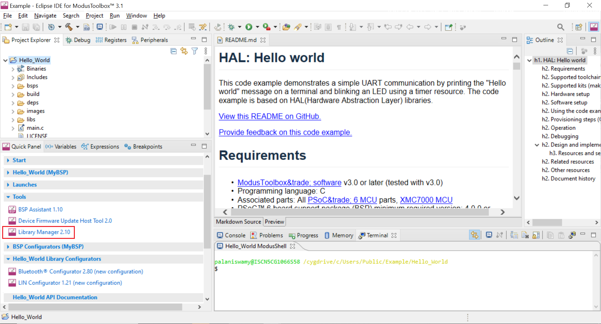
On the Library Manager window, click the Update button.
Figure 56. Update libraries 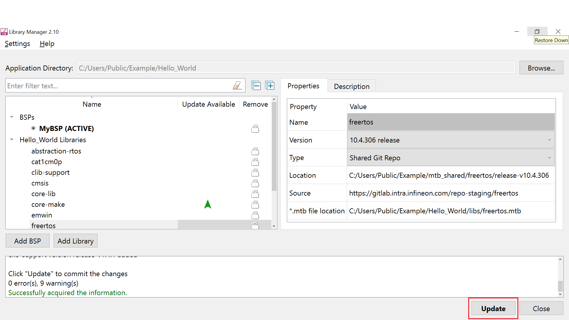
When the library updates complete, the message Successfully Updated Application shows in the console.
Figure 57. Library Manager update status 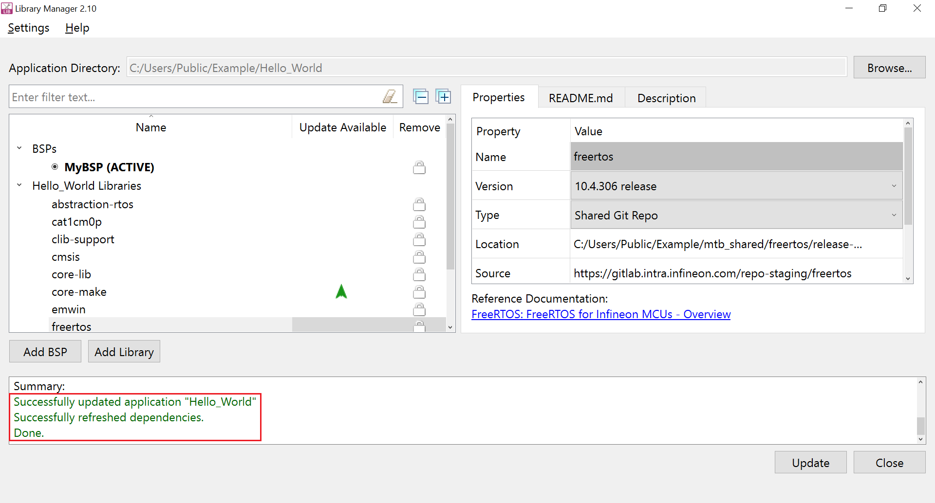
Advanced usage
ModusToolbox™ BSPs that are either custom to a user application or preconfigured made available in GitHub can belong to different generations. You can find out the generation the BSP through the following:
| BSP root directory contains the file | BSP Generation |
|---|---|
version.xml and not props.json | 3 |
props.json and not version.xml | 4 |
The BSP Assistant is only available for generation 4 BSPs using ModusToolbox™ version 3.0 or later.
Please note that BSP generation and BSP version have different meaning and should not be used interchangeably.
Differences between ModusToolbox™ BSP generations
BSP generation tools version 3 and 4 differ in the following ways:
| Property | BSP generation 3 | BSP generation 4 |
|---|---|---|
BSP configuration directory name | COMPONENT_BSP_DESIGN_MODUS | Config |
BSP build toolchain linker file name | <platform>_<cpu>.sct for Arm® <platform>_<cpu>.ld for GCC <platform>_<cpu>.icf for IAR | linker.sct for Arm® linker.ld for GCC linker.icf for IAR |
BSP version information | version tag in version.xml file in the BSP root directory | version field in props.json file in the BSP root directory |
BSP makefile name | <bsp_name>.mk |
|
BSP locate_receipe.mk file | Present | Not present |
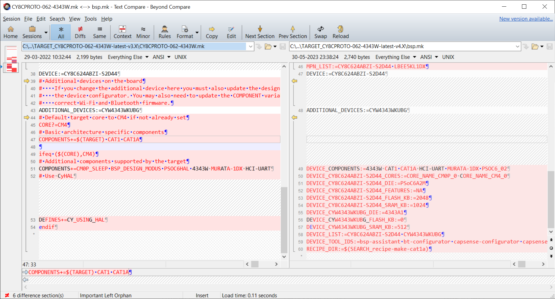
Further, the contents of the Makefile differs significantly between the generations and the below figure shows a sample comparison:
Migrating the ModusToolbox™ BSP
ModusToolbox™ custom BSPs generated through version 2.x tools can be migrated to version 3.x tools using one of the following two methods so that the user application can take advantage of the latest features of the ModusToolbox™ ecosystem.
Using the BSP Assistant tool
Create a new BSP with the BSP Assistant tool by following the steps described in the Creating a new BSP section of this document.
Update the following files in the newly created custom BSP with the settings from the corresponding version 2.x files:
- BSP configuration files including design.modus, etc.
- BSP linker files
- Add any other dependencies for the BSP other than the default dependencies by using the Add Library button in the BSP Assistant tool
Import the newly created custom BSP into your ModusToolbox™ application by running the Library Manager tool in your ModusToolbox™ application directory by clicking Add BSP and then clicking Browse on the Add or Import BSP dialog as follows:
Figure 59. Browsing to the BSP folder Caption 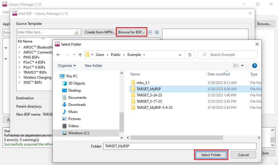
Make the new BSP active and click Update.
Figure 60. Selecting the BSP Caption 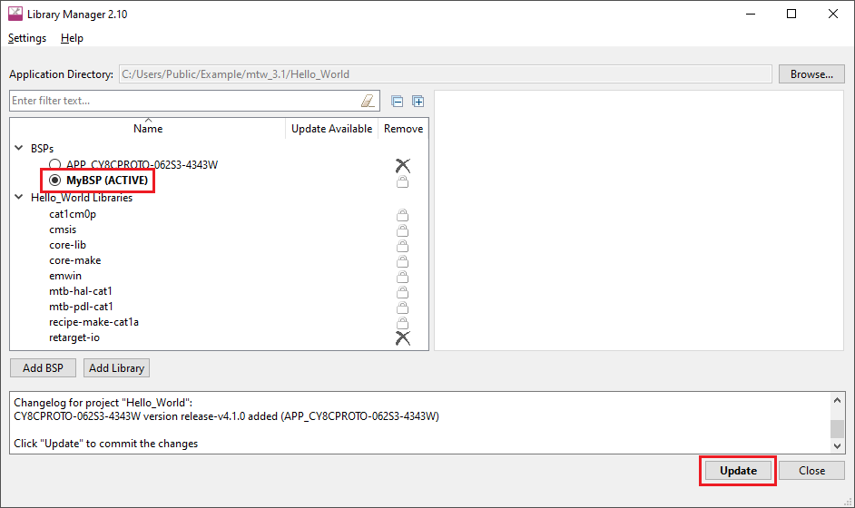
This completes the migration of the BSP from version 2.x to 3.x using the BSP Assistant tool.
Without using the BSP Assistant tool
Delete the version.xml file.
Delete the deps directory.
Create a new file called props.json and add the various properties by looking into a similar file from preconfigured 3.x BSPs in GitHub.
Rename the BSP configuration directory COMPONENT_BSP_DESIGN_MODUS to config.
Rename the BSP makefile <bsp_name>.mk to bsp.mk.
Update the bsp.mk file by comparing with an existing 3.x format bsp.mk file because there are significant changes between the 2 generations.
Rename the linker files in the directory COMPONENT_CM0P and COMPONENT_CM4 as follows:
<platform>_<cpu>.sct to linker.sct for Arm®
<platform>_<cpu>.ld to linker.ld for GCC
- <platform>_<cpu>.icf to linker.icf for IAR
- Delete the locate_recipe.mk file.
- Follow the steps in Create an application to import the new BSP to the application.
This completes the migration of the BSP from version 2.x to 3.x without using the BSP Assistant tool.
References
- ModusToolbox™ home page
- AN228571 - Getting started with PSoC™ 6 MCU on ModusToolbox™ software
- ModusToolbox™ tools package user guide
- ModusToolbox™ BSP Assistant user guide
- Creating Custom BSPs in ModusToolbox - KBA230822 (Specific to version 2. x BSPs)
- Migrating ModusToolbox™ applications from version 2.x to version 3.x - KBA236134
Revision history
| Document version | Date of release | Description of changes |
|---|---|---|
** | 2022-10-18 | Initial release. |
| *A | 2023-06-09 | Updated for ModusToolbox™ version 3.1. |